
Wear Resistance of Gear Teeth of Gearbox Gears of Tractors
Operating in Dusty Conditions
Najmiddin Mirzaev
1a
, Amirkul Irgashev
1b
and Nargiza Igamberdieva
2c
1
Tashkent State Technical University, Department of Service Technic 100095, Tashkent, Uzbekistan
2
Joint Belarusian-Uzbek Interindustry Institute of Applied Technical Qualifications in Tashkent,
100000, Tashkent, Uzbekistan
Keywords: Gearbox Wear, Abrasive Particles, Dusty Conditions.
Abstract: The article deals with the issues of wear resistance of gear teeth of wheel tractor gearboxes operating in dusty
conditions. Methods are developed: modelling of gears being in coupling with samples having a cylindrical
shape; experimental studies of wear occurring on the contact areas of the tooth profile surface, taking into
account the degree of oil contamination by abrasive particles and wear products, load and the process of
slippage between the teeth of gears.
1 INTRODUCTION
Carrying out of researches directed on determination
of term of replacement of oil in a gearbox, in real
friction pairs, demands much time and big expenses
of material means as during carrying out of tests in
field conditions oil samples are taken from a gearbox
with intervals of 125 hours of work and volume of
200-250 ml, with the subsequent filling of fresh oil in
a crankcase of the unit. The final oil sampling is
carried out after 1000 hours of operation, as the
specified time corresponds to the frequency of oil
change in the unit, according to the technical
instructions for the tractor operation for the gearbox
(Ishmuratov et al., 2023).
2 MATERIALS AND METHODS
During tractor operation, considerable amounts of
mechanical impurities accumulate in the gearbox.
The main component is abrasive particles of soil
origin, mainly consisting of oxides of silicon,
aluminium and wear products in the form of iron. The
composition of mechanical impurities in the oil was
determined by spectral analysis on the photometric
a
https://orcid.org/0009-0007-0829-5877
b
https://orcid.org/0000-0002-7826-1687
c
https://orcid.org/0000-0050-5009-0541
unit MFS-3, and the concentration of mechanical
impurities according to the results of analysis of oil
samples relating to each pair of gears of the gearbox
gears that are in the meshing.
The results of the analysis of the composition of
mechanical impurities show the presence in the oil of
the unit wear products in the form of iron, as well as
abrasive particles in the form of silicon oxides and
aluminium. The tests were carried out in the gearbox
oil during one replacement period corresponding to
1000 hours of tractor operation (Irgashev, 2005).
In order to reduce the duration, increase the
degree of accuracy of experimental studies carried out
to determine the wear resistance of gear teeth, it is
advisable to conduct tests on the friction machine,
using roller samples, whose dimensions correspond
to the geometric and kinematic parameters of the gear
gearing, which determine the radius of curvature of
the contact surfaces and the degree of slippage
occurring between the teeth of gears.
Determination of the acceleration coefficient of
wear test of gear teeth with abrasive particles is based
on a linear relationship between the concentration of
abrasive particles in the tub of the friction machine
and the amount of wear occurring in the samples of
gears with abrasive particles.
216
Mirzaev, N., Irgashev, A. and Igamberdieva, N.
Wear Resistance of Gear Teeth of Gearbox Gears of Tractors Operating in Dusty Conditions.
DOI: 10.5220/0014244500004738
Paper published under CC license (CC BY-NC-ND 4.0)
In Proceedings of the 4th International Conference on Research of Agricultural and Food Technologies (I-CRAFT 2024), pages 216-221
ISBN: 978-989-758-773-3; ISSN: 3051-7710
Proceedings Copyright © 2025 by SCITEPRESS – Science and Technology Publications, Lda.
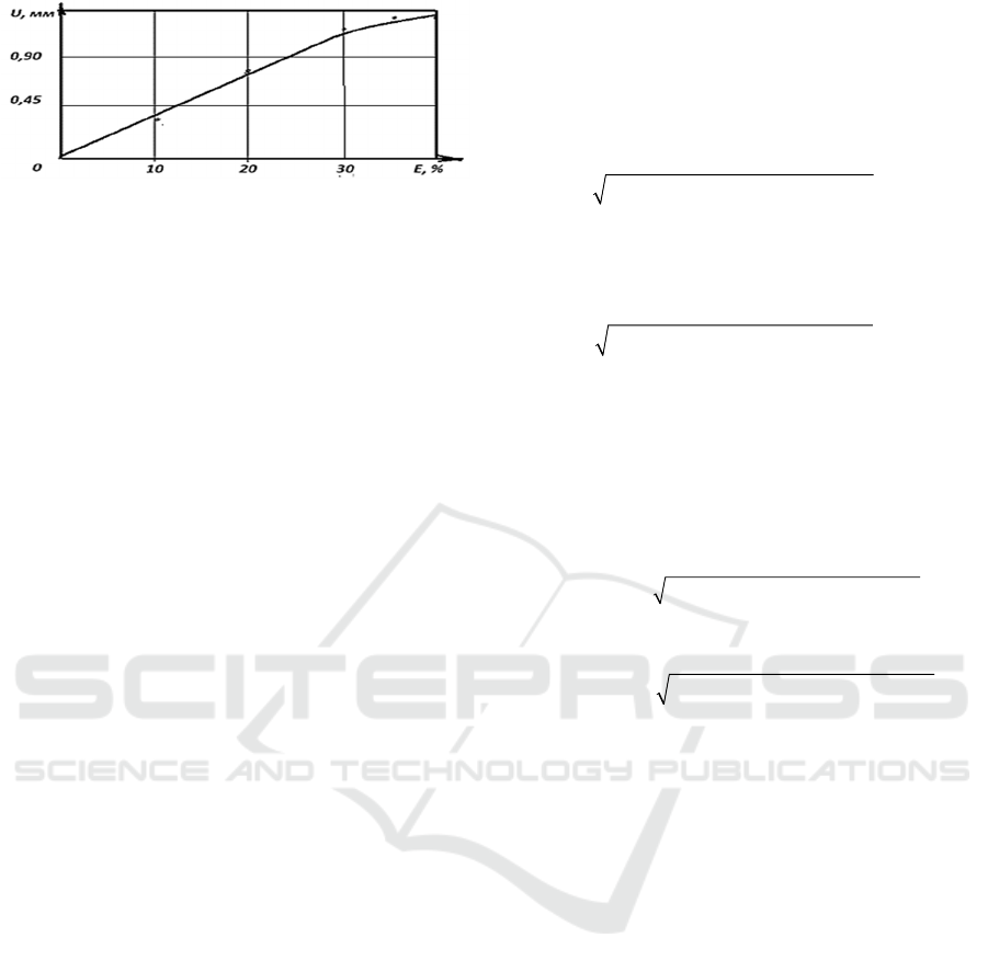
Figure 1: Variation of the wear value of the roller specimen
depending on the concentration of abrasive particles in the
oil Variation of the wear value of the roller specimen
depending on the concentration of abrasive particles in the
oil.
Carrying out of wear test on the friction machine
allows to reduce duration of works as: firstly, angular
speeds of samples established on a shaft of the
friction machine are higher, than speeds of gears in a
gearbox; secondly, concentration of abrasive
particles in oil change in operational conditions, at
dustiness of environment 0,82 g/m3, habituates 0,35
%. According to the figure 1, the dependence of
change of wear value on the concentration of
abrasive particles is linear, so the increase in the
concentration of abrasive particles is maintained up
to 31,5 %.
Increase of acceleration coefficient of wear test
(see table 1) in 158,4 times gave the possibility to
reduce the duration of wear test of gear wheel from
300 hours to 113,6 min, the test was carried out on
roller samples modelled by expressions (Ishmuratov
& Irgashev, 2020; Ishmuradov & Hamroev, 2024).
Each meshing point of the gear has its own radius
of curvature and degree of relative slip between them
according to the profile of the involute to be meshed.
In order to obtain a wear curve, the involute tooth
surface was divided into 8 parts, for each of which
the characteristic values of the degree of slippage
were determined.
Test specimens are made of gear material, the
surfaces of which are hardened in accordance with
the modes provided by the technological process of
hardening gear teeth (Myshkin & Petrokovets, 2007).
If in the gear meshing occurs between the head of
the tooth of the leading (driven) and the foot of the
tooth of the (leading) gear, then the radius of the
sample modelling the head (foot) of the tooth of the
leading (driven) gear is equal to:
1,2
0, 5
шг
m
ρψ
=⋅⋅
where
1,2
ψ
- the degree of relative slippage
occurring between the head (foot) of the tooth of the
leading (driven) and the foot (head) of the tooth of the
tooth of the slave tooth of the (driving) gear.
The calculated values of the degree of relative
slip occurring between the teeth of the meshing gears
were determined by the following expressions:
- provided that the meshing occurs between the
tooth head of the driving gear and the tooth stem of
the driven gear:
22 2
1
sin 4 sin 4
шш
z к z к
ψα α
= ⋅ +⋅⋅ ⋅ ±⋅
(1)
- provided that the engagement is between the
tooth head of the idler gear and the tooth foot of the
drive gear:
22 2
2
sin 4 sin 4
кк
z к z к
ψα α
=⋅ +⋅⋅⋅ ⋅
(2)
Then, the radius of curvature of the samples
modelling the operation of gears meshing occurs
between the head (foot) of the tooth of the driving
(driven) gear and the foot (head) of the tooth of the
driven (master) gear:
- the head (foot) of the tooth of the drive (driven)
pinion:
22 2
0,5 sin 4 sin 4
шш ш
mz к z к
ραα
=⋅⋅ ⋅ +⋅⋅⋅ ±⋅
(3)
- of the tooth of the idler gear tooth (head):
22 2
0, 5 sin 4 sin 4
кк к
mz к z к
ραα
=⋅⋅ ⋅ +⋅⋅⋅ ⋅
(4)
The sizes of abrasive particles participating in the
process of wear are chosen according to GOST 9206-
80 26/22, 10/8,5 microns and the sizes of the same
abrasive particles according to GOST 3647-80 are
designated by M28, M10. Average sizes of abrasive
particles added to oils in a tub of the friction machine
at wear test made 14,9 microns.
Duration of testing samples of gears for wear
resistance on the friction machine depend on the
material of gear teeth, modes of heat treatment,
geometric and kinematic parameters, coefficient of
acceleration of wear test. Calculated indicators
affecting the coefficient of acceleration of wear test,
wear resistance and duration of wear test of samples
made of gear materials on the rolling friction
machine are given in Table 1.
Wear Resistance of Gear Teeth of Gearbox Gears of Tractors Operating in Dusty Conditions
217
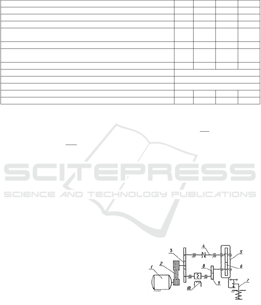
Table 1: Gear indicators affecting the test acceleration factor and the duration of the wear test of the specimens.
Indicatorsnwear test II III IY Total
P
ercenta
g
e of oil chan
g
e time, % 15 30 25 70
P
roportion of oil chan
g
e time, hours 150 300 250 700
A
vera
g
e speed of driven shaft, min
-1
476 567 667 -
N
umber of revolutions of the output shaft during the oil change period
(ten thousand revolutions)
428,4 1020,6 1000,5 2449,5
R
otational speed of the lower sample, min
-1
1000 1000 1000 -
N
umber of revolutions of the lower friction sample (ten thousand
r
evolutions)
900 1800 1500 4200
A
cceleration coefficient of test specimens and
g
earbox drive shaft tes
t
2,10 1,76 1,50 1,71
Concentration of abrasive accumulations durin
g
the oil chan
g
e period, % 0,35
Concentration of abrasive particles in friction machine oil, % 31,5
Test acceleration factor at 31.5% abrasive particle concentration in oil 90
Total test acceleration facto
r
189,0 158,4 135,0 153,9
D
uration of the wear test on the friction machine 47,6 113,6 111,1 272,3
The speed of rotation of the drive shaft of the
gearbox during one minute is determined by the speed
of rotation of the engine crankshaft, according to the
ratio below:
д
i
ду i
n
n
ii
=
⋅
where
д
n
- the frequency of rotation of the
crankshaft of the engine during one minute,
д
n =
2200 min
-1
;
ду
i
- the gear ratio of the gear
transmission, transferring torque to the intermediate
shaft of the transmission box, with the value
ду
i
=1,29,
which will provide the average speed of rotation of
the intermediate shaft 1700 min
-1
. The number of
revolutions of the driving shaft of the gearbox perfect
for one term of oil change is calculated by the
following expression:
ма i мх
N
nt=⋅
where
м
х
t
- gearbox oil change period, min
The wear test was carried out on the friction
machine on samples made on the radius of curvature
of gear teeth, heat treatment of friction surfaces of
which was carried out taking into account the load to
the real conditions of operation of gear wheels, taking
into account their location in the intermediate and
driven shafts of the transmission box. Thus tested
lower samples had contact with oil in a bath of the
friction machine having a composition of abrasive
particles. The wear test of the specimens was carried
out at the rotational speed of the bottom specimen of
the friction machine 1000 min
-1
.
The general coefficient of acceleration of wear
test includes two components, one of them takes into
account the rotational speed of the bottom specimen
mounted on the friction machine and is determined by
the expression:
им
ас
у
к
N
к
N
=
where
им
N
- number of revolutions of the lower
sample tested for wear resistance on the friction
machine;
ук
N
- number of revolutions of the driven
shaft for the period of oil change in the gearbox.
The second component was determined by the
ratio of the maximum concentration of abrasive
particles in the oil of the friction machine tub, which
has a linear dependence on the maximum wear of the
samples (1.25 mm), presented in Figure 1.
At carrying out of experimental researches the
used abrasive particles on maximum and minimum
sizes and on strength have special values which
should correspond to requirements of GOST 9206
and GOST 3647-80.
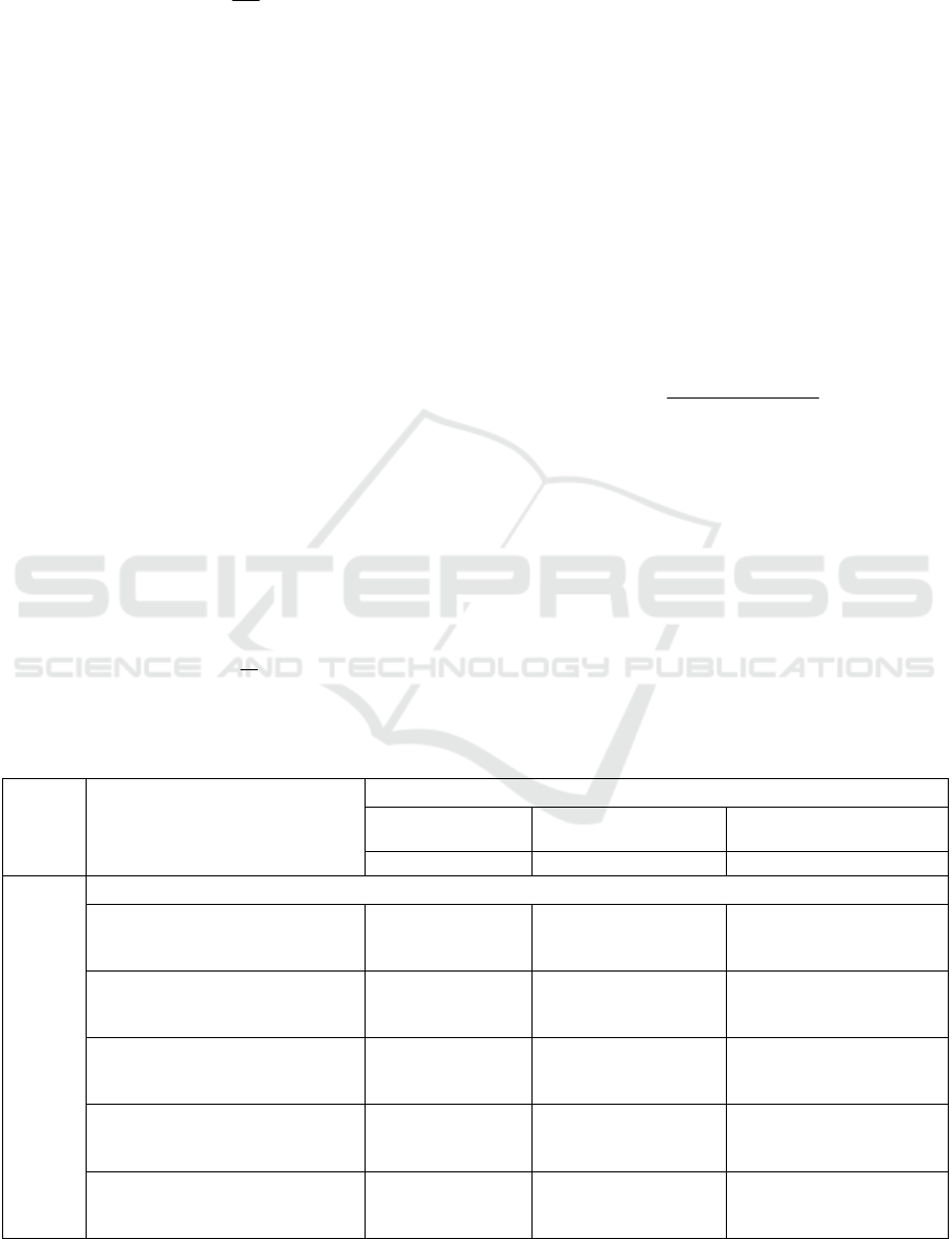
Figure 2: Kinematic scheme of the rolling friction machine
1 - electric motor; 2 - V-belt transmission; 3 - gear transfer
box; 4 - shaft; 5 - carriage; 6 - gear drive upper sample; 7 -
spring loading mechanism; 8 - upper sample; 9 - lower
sample; 10 - inductive sensor for measuring the friction
torque.
I-CRAFT 2024 - 4th International Conference on Research of Agricultural and Food Technologies
218
The acceleration factor of a wear test involving
abrasive particles in oil is equal to:
им
а
у
к
к
ε
ε
=
where
им
ε
- concentration of abrasive particles in
the tub of the friction machine before the test, %;
ук
ε
- concentration of abrasive particles in the gearbox oil
corresponding to the period of their replacement, %.
The calculated values of the acceleration coefficient
of the wear test were
а
к =
90.
The total coefficient of acceleration of wear test is
determined as a product of coefficients of
acceleration of wear test of samples, being in oil bath
of the friction machine (Fig. 2) and with participation
of abrasive particles in oil, that is:
ас а
кк к=⋅
where
ас
к
- acceleration coefficient of wear test of
specimens being in the oil bath of the friction
machine.
Time wear test on the friction machine friction
samples made of gearbox gear materials, determined
for the period of oil change for each gear, taking into
account their share in each gear and the coefficient of
acceleration of wear resistance test, is determined by
the following ratio:
х
им
t
t
к
=
where t
x
- the fraction of oil change time in the
gearbox under consideration, min.
3 RESULTS AND DISCUSSION
Determination of the average wear rate of gear teeth
arising during the oil change period of the tractor
gearbox operating in an abrasive environment, makes
it possible to determine the service life of gears in
operating conditions. Modelling the work of gear
teeth involved in meshing samples - roller analogues
on the basis of geometric and kinematic parameters
allows you to reduce the duration of wear test and has
an impact on improving the accuracy of measurement
of wear of the friction surfaces under study.
For definition of average wear rate of samples the
following expression is offered:
0,033
м
м
ем
М
в t
γ
πγ ρ
=
⋅⋅ ⋅⋅⋅
where - value of wear of the sample by mass, g; -
density of wear products, g/mm3; - radius of the
tested sample for wear by mass, mm; - contact width
of the tested sample for wear, mm; - duration of wear
test of the sample, min.
The value of wear of the samples tested for wear
resistance was determined by weighing on analytical
scales by the difference in mass of samples before and
after wear test, the measurement was carried out with
an accuracy of 0.1 mg. The results of the study are
given in Table 2.
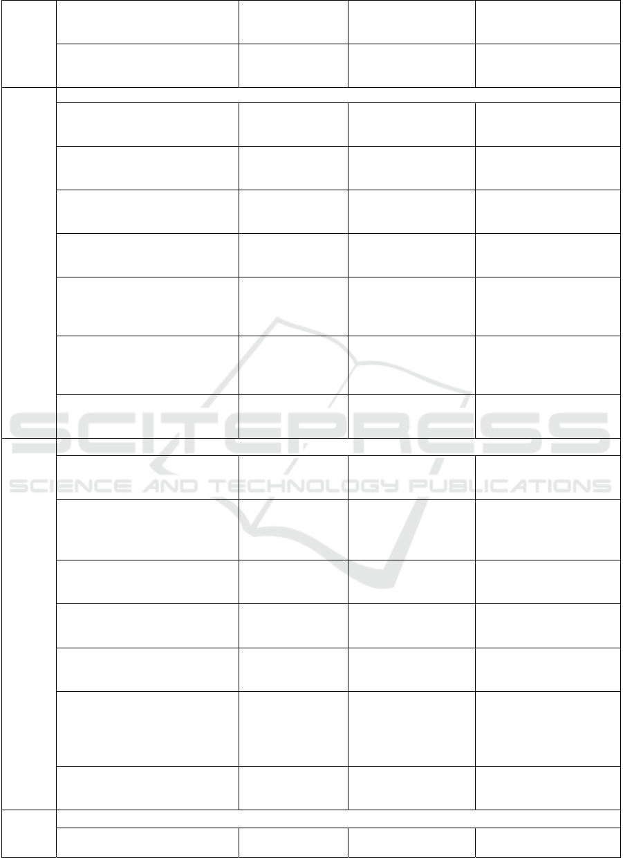
Table 2: Results of wear test of specimens made of gear materials on the radius of curvature curvature of gear teeth, carried
out on a rolling friction machine.
№
Indicators
Gear tooth height factor, k
On the head of the
tooth
At the engagement pole On the stem of the tooth
1,0 0 1,0
1
Radius of curvature of tested samples of gear teeth, mm
On a permanent hitch:
on the drive shaft;
intermediate shaft
28,94
35,78
23,94
30,78
28,06
35,07
In first gear:
intermediate shaft;
idler shaft
49,46
15,26
44,46
10,26
48,95
13,53
In second gear:
intermediate shaft;
idler shaft
47,75
16,97
42,75
11,98
47,22
15,43
In third gear:
the intermediate shaft;
idler shaft
46,03
18,68
41,04
13,68
45,49
17,29
In fourth gear:
intermediate shaft;
idler shaft
44,33
20,39
39,33
15,39
43,76
19,12
Wear Resistance of Gear Teeth of Gearbox Gears of Tractors Operating in Dusty Conditions
219
In fifth gear:
intermediate shaft;
idler shaft
38,34
26,38
33,34
21,38
37,69
25,41
In sixth gear:
intermediate shaft;
idler shaft
32,36
32,36
27,36
27,36
31,58
31,58
2
Wear value of the gear test specimen by mass, g
r
On a permanent hitch:
on the drive shaft;
intermediate shaft
0,071
0,088
0,007
0,009
0,069
0,086
In first gear: intermediate shaft;
idler shaft
0,121
0,037
0,012
0,004
0,120
0,033
In second gear:
intermediate shaft;
idler shaft
0,117
0,042
0,012
0,004
0,116
0,038
In third gear:
intermediate shaft;
idler shaft
0,113
0,046
0,011
0,005
0,111
0,042
In fourth gear:
intermediate shaft;
idler shaft
0,109
0,056
0,011
0,006
0,107
0,047
In fifth gear:
intermediate shaft;
idler shaft
0,094
0,065
0,009
0,007
0,092
0,062
In sixth gear:
intermediate shaft;
idler shaft
0,079
0,080
0,008
0,008
0,077
0,077
3
Value of linear wear of the gear test specimen, mm
On a permanent hitch:
on the drive shaft;
intermediate shaft
0,644
0,499
0,061
0,047
0,614
0,476
In first gear:
Intermediate shaft
idler shaft
0,065
0,015
0,006
0,002
0,062
0,014
In second gear:
intermediate shaft;
idler shaft
0,134
0,038
0,013
0,004
0,128
0,036
In third gear:
intermediate shaft;
idler shaft
0,257
0,086
0,024
0,008
0,245
0,082
In fourth gear:
intermediate shaft;
idler shaft
0,205
0.080
0,020
0,008
0,196
0,076
In fifth gear:
gear on the intermediate shaft;
pinion on the idler shaft
0,104
0,067
0,010
0,006
0,099
0,065
In sixth gear:
intermediate shaft;
idler shaft
0,046
0,046
0,005
0,005
0,044
0,044
4
Wear rate of the gear sample, mm/hour
On a permanent hitch:
on the drive shaft;
0,00064
0,00006
0,00061
I-CRAFT 2024 - 4th International Conference on Research of Agricultural and Food Technologies
220
intermediate shaft 0,00050 0,00005 0,00048
In first gear:
intermediate shaft;
idler shaft
0,00093
0,00021
0,00009
0,00002
0,00089
0,00020
In second gear:
intermediate shaft;
idler shaft
0,00089
0,00025
0,00008
0,00002
0,00085
0,00024
In third gear:
intermediate shaft;
idler shaft
0,00086
0,00029
0,00008
0,00003
0,00082
0,00028
In fourth gear:
intermediate shaft;
idler shaft
0,00082
0,00032
0,00008
0,00003
0,00078
0,00031
In fifth gear:
intermediate shaft;
idler shaft
0,00069
0,00045
0,00007
0,00004
0,00066
0,00043
In sixth gear:
intermediate shaft;
idler shaft
0,00058
0,00058
0,00005
0,00005
0,00055
0,00055
4 CONCLUSIONS
1. Analytical dependencies are offered, allowing
to calculate the degrees of relative slippage
occurring between the teeth of the meshed
gears and radius of curvature of the contact line
radius of the teeth of the driving and driven
gears taking into account, geometric and
kinematic parameters of the gear meshing.
2. Developed a method of accelerated wear test of
the gear gearing modelling the work of gear
teeth roller samples made by their radius of
curvature, while providing high accuracy of the
results obtained on the wear profile of gear
teeth determined by wear test roller analogues.
3. Analytical dependence is obtained, allowing to
determine the wear rates of the teeth of the
driving and driven gears, taking into account
the values of wear on the mass of samples,
radius of curvature, contact width and duration
of wear test.
REFERENCES
Irgashev, A., 2005. Methodological bases of increase of
wear resistance of gears of heavy-loaded gears of
machine units. Dissertation of Doctor of Technical
Sciences, Tashkent, p. 244.
Ishmuradov, Sh. & Hamroev, R., 2024. Disc rotary plough
for agriculture mechanization. E3S Web of Conferences,
548, 08017.
https://doi.org/10.1051/e3sconf/202454808017.
Ishmuratov, H.K., Irgashev B.A., 2020. Assessment of the
wear resistance of gearwheel teeth in an open toothed
gear under the conditions of a high level of dust.
Journal of Friction and Wear, 41(1), 85-90.
https://doi.org/10.3103/S1068366620010092.
Ishmuratov, H.K., Mirzaev, N.N., Abdullaeva, B.,
Mamasalieva, M.I., 2023. Energy analysis of wear
sliding friction units. E3S Web of Conferences, 383,
04019. https://doi.org/10.1051/e3sconf/202338304019.
Myshkin, N.K. & Petrokovets, M.I., 2007. Friction,
lubrication, wear. Physical Bases and Technical
Applications of Tribology. Moscow: Fizmatlit, p. 368.
Wear Resistance of Gear Teeth of Gearbox Gears of Tractors Operating in Dusty Conditions
221
