
Substantiation of Basic Parameters of Gear Teeth of Open Gears on
Wear Resistance
Ishmuratov Hikmat
a
and Mamasalieva Mukaddas
b
Tashkent State Technical University, 100095, University str. 2, Tashkent, Uzbekistan
Keywords: Gear Teeth, Wear Resistance, Open Gear Transmission.
Abstract: In the article the method of calculation of speed of wear of open gear transmission by protrusions of roughness
which are on surfaces of friction of teeth having rounded forms, in the presence of slipping between teeth of
gears and pure rolling occurring in a zone of contact of initial circles of meshing gears without participation
of abrasive particles, taking into account bending stress arising at transmission of circumferential force is
resulted. As a result of the formation on the friction surfaces of the teeth of the teeth of the open gear
transmission of the equilibrium roughness is accompanied by an increase in the actual contact area of the teeth.
Therefore, the friction surfaces of gear teeth can operate without seizure at higher loads. Roughness of gear
teeth surfaces, formed as a result of mechanical processing, under friction under the influence of
circumferential force in meshing accompanied by rolling and slipping are subjected to plastic deformation.
1 INTRODUCTION
For open gears the most characteristic type of loading
leading to tooth breakage is the bending stress arising
from the circumferential force in the meshing. The
radial component of the circumferential force
deforming the roughness of the friction surfaces of
gear teeth leads to the formation of equilibrium
(operational) roughness, differing from the original
(technological) form (Myshkin et al., 2007; Dubovik,
2015; Ishmuratov, 2019; Mamasalieva, 2024).
Profilograms obtained from the friction surfaces of
gear teeth after the formation of equilibrium
roughness show that their protrusions and hollows of
irregularities have relatively close dimensions in
height and has a sufficiently large radius of
volumetric curvature than at the technological
roughness (Mamasalieva, 2024). As a result of the
formation of equilibrium roughness on the friction
surfaces of the teeth of the open gear transmission, the
actual contact area of the teeth is increased.
Therefore, the friction surfaces of gear teeth can
operate without seizure at higher loads. According to
the theory of fatigue wear, wear products from the
friction surfaces of gear teeth are separated after a
small number of repeated deformation protrusions of
a
https://orcid.org/0009-0008-2266-0372
b
https://orcid.org/0000-0002-9175-905X
roughness having a rounded shape. As a result, the
process of wear of gear teeth occurs in the presence
between the teeth of rolling with slippage, occurring
on the head and foot of the teeth, and wear of teeth in
the pure rolling occurring in the contact zone of the
initial circles. For these types of contact of gear teeth
the rate of wear is determined.
2 MATERIALS AND METHODS
Taking into account the research results given in
(Gorlenko et al., 2014; Ishmuratov, 2019) and in
order to simplify the calculation of wear rate, the
protrusions of roughnesses of tooth friction surfaces,
participating in the process of wear are modeled in the
form of spheres (Fig. 1) with the volume radius equal
to (r).
At contact, in the process of wear of gear teeth,
roughness protrusions are embedded to the rubbing
surfaces, and under the influence of the radial
component of the circumferential force transmitted
by the gear mesh, these roughnesses can be partially
deformed. When slippage occurs between the gear
teeth, the embedded roughness protrusions plow a
Hikmat, I. and Mukaddas, M.
Substantiation of Basic Parameters of Gear Teeth of Open Gears on Wear Resistance.
DOI: 10.5220/0014242500004738
Paper published under CC license (CC BY-NC-ND 4.0)
In Proceedings of the 4th International Conference on Research of Agricultural and Food Technologies (I-CRAFT 2024), pages 191-196
ISBN: 978-989-758-773-3; ISSN: 3051-7710
Proceedings Copyright © 2025 by SCITEPRESS – Science and Technology Publications, Lda.
191
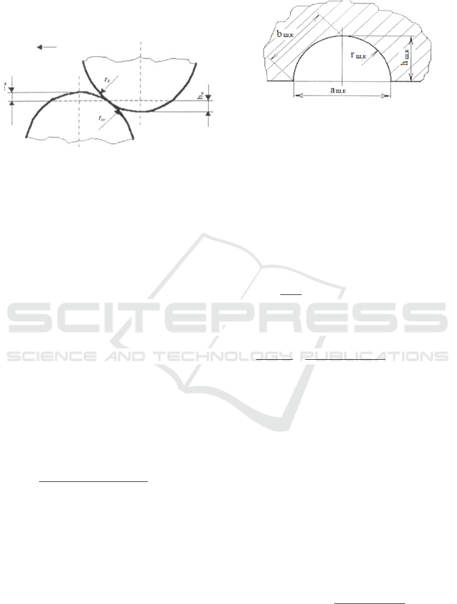
deepened path on the friction surfaces of the teeth
(Myshkin et al., 2007).
Figure 1: Schematic of contact of roughness protrusions
during friction.
In the process of force interaction of meshing gear
teeth, the volume of deformed material depends on
the depth of embedding, the radius of volume
curvature of roughness protrusions, the path of
relative slippage of teeth, the number of roughness
protrusions located along the length of the width of
the contact area and which participate in the process
of deformation of friction surfaces (Myshkin et al.,
2007).
3 RESULTS AND DISCUSSION
Wear resistance, in the presence of slippage between
gear teeth. According to the results of the study
obtained in the works (Myshkin et al., 2007),
(Ishmuratov, 2019), (Gorlenko et al., 2014),
(Ishmuratov et al., 2023), (Irgashev, 2005), between
the diameter of the contact spot introduced to the
friction surfaces of the teeth roughness protrusions
and the circumferential force (P) acting on these
protrusions, at the contact of friction surfaces of gear
teeth there is a relationship:
4
,
2
, кшобкш
HМca
P
⋅⋅⋅⋅
=
π
, Н (1)
where aш,к - diameter of the contact spot of the
introduced roughness protrusion to the friction
surfaces of teeth, m; c - coefficient depending on the
shape of protrusions and on the hardening of the
material (Ishmuratov 2019); Mоб - the total number
of roughness protrusions located on the working area
of contact of teeth; - hardness of the material of the
driving (driven) gear, MPa.
Figure 2: Scheme for determination of geometrical
parameters of roughness protrusion introduction into the
friction surface of gear teeth.
To calculate the tooth wear rate, it was
conventionally assumed that the dimensions of the
roughness protrusions in terms of height and
volumetric radius of curvature are the same. Which
are located sequentially along the length and height
of the tooth. During friction, the roughness
protrusions are partially embedded in the friction
surfaces of the contacted tooth surfaces. According to
the accepted conditions of arrangement of protrusions
of roughness of friction surfaces, their number of
located along the length of gear teeth L, is equal to:
кш
a
L
М
,
=
.
Then the load carried by a single roughness
protrusion:
4
,
2
,, кшкшкш
Hca
L
aP ⋅⋅⋅
=
⋅
π
,
We assume that the circumferential force
transmitted by the open gear working in dry friction
are perceived by the protrusions of irregularities
located on the contact surface of the teeth, their
strength depends on the bending stress arising at the
foot of the teeth, then the circumferential force
perceived by all protrusions of irregularities located
on the contact area of the teeth is equal:
кш
кш
из
аМmkР
,
,
2 ⋅⋅⋅⋅⋅=
σ
(2)
where is the maximum bending stress occurring
on the plane of the circle of the troughs located on the
tooth leg of the driving (driven) gear, MPa; is the
coefficient of tooth height relative to the dividing
circle of the gears; m is the meshing module, m.
For approximate calculations, equating
expressions (1) and (2) and solving them with respect
to the hardness of the material is obtained:
ca
mk
H
кш
кизш
кш
⋅⋅
⋅⋅⋅
=
,
,
,
8
π
σ
.
I-CRAFT 2024 - 4th International Conference on Research of Agricultural and Food Technologies
192

From the obtained expression it is possible to
obtain the ratio of material hardness and bending
stress in the gear mesh, the optimal value of which is
approximated as Hш,к = 1.88.σ из ш,к..
Due to the fact that the contact patches of the
embedded roughness protrusion has an approximate
circular shape then the contact patches of the friction
surface of the teeth of the driving (driven) gears, is
calculated by the expression (Irgashev, 2005),
кш
кизш
кш
кш
Hc
km
HcL
P
a
,
,
,
,
54,2
27,1
⋅
⋅⋅⋅
=
⋅⋅
⋅
=
σ
, м. (3)
According to the scheme presented in Fig. 2 the
depth of introduction of roughness protrusions to the
friction surfaces at the contact of gear teeth is
determined and the dependence is obtained,
кшкш
шк
кш
Hc
a
h
,,
,
0019,0
θ
⋅
⋅
=
, м (4)
There is a relationship between the volume radius
of curvature rш,к and the depth of introduction of the
roughness protrusion of the gear teeth hш,к
(Ishmuratov and Irgashev, 2020):
кшкш
кш
Hc
h
r
,,
,
3
θ
⋅⋅
=
, м (5)
The length of the chord of the segment (bш,к ),
formed as a result of embedding a rounded roughness
protrusion, is determined according to the scheme
shown in Fig. 2, in which the calculated values of the
contact spot diameter aш,к , embedding depth hш,к
and volume radius of curvature (rш,к ) of roughness
protrusions are taken into account,
5,0
,,
,
,,,
)(
816,0
2
кшкш
кш
кшкшkw
Нс
h
rhb
θ
⋅⋅
⋅
=⋅⋅=
, м. (6)
We calculate the cross-sectional area of the
deformed metal volume as a result of the introduction
of a single roughness protrusion located on the
friction surface of the teeth of the driving (driven)
gear (Ishmuradov et al., 2024):
(
)
кш
изкшкшкшшк
кш
Hс
mhkbah
F
,
,,,
,
448,2
15
86
⋅
⋅⋅⋅⋅
=
+⋅
=
σ
, m
2
. (7)
The number of roughnesses located on the tooth
length of the driving (driven) gear (Irgashev, 2005)
taking into account the expression (3), we obtain:
из
кш
mk
HcL
М
σ
⋅⋅
⋅⋅⋅
=
,
39,0
(8)
Considering the value of the cross-sectional area
of the deformed volume of metal la as a result of
introduction of one roughness protrusion from (7),
paths of relative slip of roughness protrusions located
on the surface of contacted teeth (Ishmuradov et al.,
2024) and the number of roughnesses located on the
tooth length of gears M calculated by the expression
(8) after some simplification we obtain the expression
for calculation of the volume of deformation of the
material of the driving (driven) gear, by all
protrusions of roughnesses located on the contact
surface, in the presence of slip between the teeth of
gears is equal to:
ψ
⋅+⋅⋅⋅⋅== )1(
3
,
,
,,,,
imLh
z
МsFv
кш
кш
кшкшкшкш
, m
3
(9)
Here, the slip coefficient of the contacted gear
teeth is denoted by , which is defined through the
reduced number of teeth,
ααψ
sin44sin
222
пршпр
zkkz −±+=
,
where is the reduced number of gear teeth, ; here
zш , zк are the numbers of teeth of the driving and
driven gears, respectively.
In the expression, the plus sign in front of is
placed when the tooth head slip is calculated, the
minus sign is used to calculate the tooth foot slip.
In the process of friction roughness protrusions of
teeth of one gear for each cycle of loading contact
with different protrusions of roughness of another
gear. And the roughness of the teeth of these gears
differ from each other in density of arrangement on
the tooth surface and in size. In addition, during
contact, the roughness protrusions themselves may
partially deform and change their original shape. The
same roughness protrusion and deformed counter
body surface can meet each other after a certain
number of loading cycles of gears, which is taken as
the probability of re-deformation, to calculate the
value, its obtained dependence (Ishmuradov et al.,
2024):
кшкш
из
кшкш
из
кш
kw
НcLz
mk
НcLz
mk
Мz
,,,,,
,
56,2
39,0
1
⋅⋅⋅
⋅⋅⋅
=
⋅⋅⋅⋅
⋅⋅
=
⋅
=
σ
σ
η
(10)
Failure of deformed surfaces of gear teeth occurs
according to the fatigue theory of wear, after a certain
number of repeated loadings.
The number of loading cycles leading to the
destruction of the deformed tooth surface of the
driving (driven) gear is equal to:
()
t
кшкшp
n
,,
ψ
=
(11)
where is the coefficient of relative elongation of
the leading (driven) gear material; t is the coefficient
of frictional fatigue of the gear material, for gears
made of steel, t=1.3.
Then, in general, the wear rate of gear teeth of
open gears, in the presence of slippage between gear
teeth is determined by:
Substantiation of Basic Parameters of Gear Teeth of Open Gears on Wear Resistance
193
()
()
кшp
кшкшкш
кшд
nF
nv
,
,,,
,
⋅
⋅⋅
=
η
γ
, m/h (12)
where nш,к is the speed of rotation of the driving
(driven) gear; F is the area of contact of meshing pairs
of gear teeth F=BL.
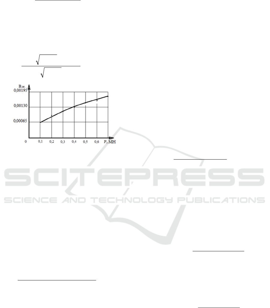
Widths of contact of gear teeth of the zone of
initial circles is calculated by the expression
(Ishmuradov et al., 2024):
пр
пр
EL
P
B
⋅
−⋅⋅⋅
=
)1(04,3
2
μρ
, м, (13)
Figure 3: Variation of tooth contact width from
circumferential force in a gear mesh.
where μ is the Poisson's ratio; is the reduced
radius of curvature of the rolling zone gear teeth.
The graph of change in the contact width of the
teeth, depending on the circumferential force
presented in Fig. 3 is obtained by expression (12) with
the following initial data: =9,78; =0,03; Eпр =
215000 MPa shows that increasing the contact width
of the gear teeth leads to an increase in the
circumferential force transmitted by the gear.
Substituting the values from expression (9) , η
,wk from (10) and (11) into (12) taking into account,
and after some simplification, we obtain an
expression for calculating the wear rate of the driving
(driven) gear, in the presence of slippage between the
teeth,
()
кшкршкшпрпр
изкшкш
kwд
НnсzLЕ
Рknimh
,,
2
,
25,0
5,0
,,
,
)1(
)1(8,910
⋅⋅⋅⋅−⋅⋅⋅
⋅⋅⋅⋅⋅+⋅⋅⋅
=
μρ
σψ
γ
,m/h (14)
In Table 1 as an example of the results of
calculation of the amount of wear of the teeth of the
pinion gears of the driving gear depending on the
meshing module in the presence of slippage between
the teeth of the gears ψ = 1.035, the coefficient of
tooth height from the initial circumference of the
driving gear k = 1; the speed of rotation of the driving
gear nш = 2.92 r / s; maximum bending stress at the
foot of the teeth σиз = 153.7 MPa; reduced modulus
of elasticity Eпр =215000MPa; gear ratio i=0,125
(gear accelerating); number of teeth of the driving
pinion zш =88; deformation factor c = 3; hardness of
the material of the driving pinion Hш =282 MPa; the
number of deformation cycles leading to the
destruction of the deformed surface of the driving
pinion at =6% is nрш = 10,273. The results of
calculating the resource of the driving pinion are
shown in the table. For calculation it is accepted that
according to the recommendations proposed in the
"Encyclopedia of Mechanical Engineering XXL"
limit wear of gear teeth is 20% of the tooth thickness.
Wear resistance of gear teeth, when rolling. In the
rolling zone of gear teeth, the process of wear as noted
above occurs as a result of deformation of localized
volumes of metal friction surfaces. When between the
friction surfaces of gear teeth are absent slippage
from the introduction of protrusions of roughness in
their contact zone formed crater-shaped wells, with
wear products are formed after a certain number of
repeated deformation of the friction surface of gear
teeth protrusions of roughness rounded shape. In this
case, the rate of wear of gear teeth in the contact zone
of the initial circles, when rolling in general form is
determined by the expression:
),(
,),(1
),(
kwpnk
kwоkwн
kwд
nF
nMv
⋅
⋅⋅⋅
=
η
γ
δ
,m/hour (15)
where Mоб is the total number of roughness
protrusions located on the contact area of gear teeth.
To calculate the deformed volume of metal of
contact surfaces of gear teeth with one roughness
protrusion of spherical shape, taking into account the
diameter of the contact spot aw,к and hardness of the
gear material H ,w,к when the roughness protrusion
of the tooth surface has a rounded shape, when rolling
the zone of the initial circles of the contacted gear
teeth, the dependence [7] is obtained:
шк
изгкш
wkH
Hс
mk
v
⋅⋅
⋅⋅⋅
⋅=
9
75,5
3332
,
)(1
σθ
, m
3
(16)
In the contact zone of the initial circles of the
meshing gears - the value of the gear tooth height
coefficient in the zone of the initial circle k can be
represented by the ratio of the tooth contact width to
the meshing modulus,
шк
изгкш
wkH
Hс
В
v
⋅
⋅⋅
⋅=
332
,
)(1
639,0
σθ
,
then expression (16) has the form,
The contact areas of the friction surfaces of the
rolling zone of the gear teeth are equal:
BLF
n к
⋅=
, m
2
(17)
The amount of deformation of friction surfaces
depends on the number of roughness protrusions . To
I-CRAFT 2024 - 4th International Conference on Research of Agricultural and Food Technologies
194
calculate the number of roughness protrusions located
along the contact width of gear teeth, the dependence
is obtained:
из
кшшк
b
ВE
Hc
М
σ
μρ
⋅⋅
⋅⋅−⋅⋅
=
,
2
)1(69,1
(18)
The number of consecutive roughnesses located
on the tooth length of the driving (driven) gear is
determined by expression (8).
Table 1: Basic parameters of calculation on wear resistance of teeth of the driving pinion of open gear
transmission.
Hitching modulus
m, m
Shes-tern tooth length
L, m
The width of the con-
tine tact B, m
Tooth contact area F
к
, m
2
Hitching modulus
m, m
Tooth base area F
о
, m
2
Bending stress, at the tooth
foot
σ
,
MPa
Hitching modulus
m, m
Depth of penetration of the
roughness protrusion
h
Radius of curvature of the
p
inion contact point
Drive gear tooth wear rate
ш
γ
m/hour
Permissible wear of gear tooth,
m
Resource
leading
gears,
hour
1 2 3 4 5 6 7 8 9 10 11 12 13
0,001 0,025 0,0001
2
0,0000069
6
0,014 0,0000910
6
153,
7
0,001 0,0001
4
0,0016
7
0,000000066
2
0,00031
4
4743
0,002 0.029 0,0002
4
0,0000139
2
0,028 0,0001821
2
153,
7
0,002 0,0002
8
0,0033
4
0,000000162
2
0,00062
8
3872
0,004 0,037 0,0004
8
0,0000278
4
0,056 0,0003642
4
153,
7
0,004 0,0005
6
0,0066
8
0,000000359
6
0,00125
6
3492
0,006 0,045 0,0007
2
0,0000417
6
0,084 0,0005463
6
153,
7
0,006 0,0008
4
0,0100
2
0,000000543
2
0,00188
4
3468
0,008 0,053 0,0009
6
0,0000556
8
0,112 0,0007284
8
153,
7
0,008 0,0011
2
0,0133
6
0,000000710
0
0,00251
2
3538
0,010 0,061 0,0012
0
0,0000696
0
0,140 0,0009106
0
153,
7
0,010 0,0014
0
0,0167
0
0,000000862
1
0,00314
0
3642
According to [8], in the contact zone of the initial
circles of the meshing gears, only rolling occurs,
without slippage of the teeth. For this case:
radius of curvature of the tooth profile of the drive
gear,
αρ
sin5,0 ⋅⋅⋅=
шш
zm
, м;
radius of curvature of the tooth profile of the
driven gear,
αρ
sin5,0 ⋅⋅⋅⋅= izm
шk
, м.
The total number of roughness protrusions located
on the tooth contact area, taking into account
expressions (8) and (18) is equal:
3
3
,
22
)(
)1(34,0
из
кшшк
bоб
BE
HcL
MММ
σ
θμρ
⋅⋅
⋅⋅⋅⋅−⋅⋅
=⋅=
(19)
The calculated value of the probability of repeated
deformation , by the roughness protrusion of the
same deformed surface is determined by the
dependence (10) [9]:
Substituting the values of η from (10), from (11),
v1н(w,k) from (12), Fnк from (16), Mоб(ш,к) , from
(19), into (14) finally obtains:
PLi
nB
t
кш
кшизкш
kwд
м/ч. ,
5950
2/1
,
2/1
,
2/52/52
,
),(
⋅⋅⋅
⋅⋅⋅⋅
=
ψ
σθ
γ
(20)
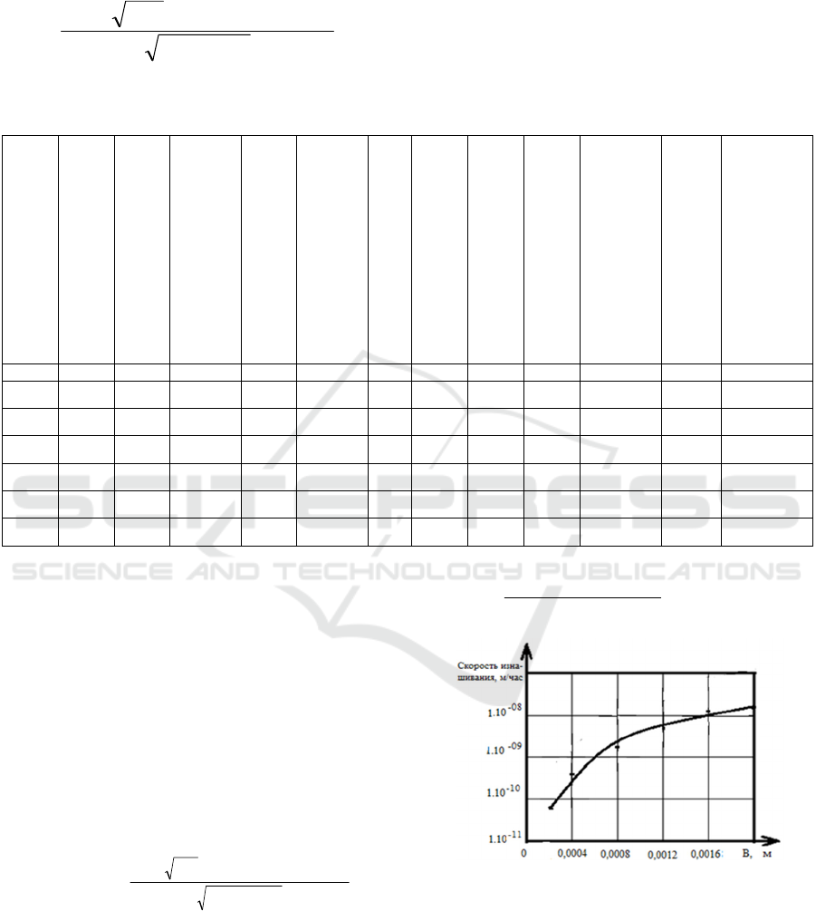
Figure 4: Variation of the wear rate of the driving gear tooth
depending on the contact width of the gear teeth.
The resulting expression show that the rate of
wear of gear teeth in the contact zone of the initial
circles of the initial circles of the meshing gears,
rolling zone depends on the tooth length, gear ratio
and frictional fatigue of the material, the width of
Substantiation of Basic Parameters of Gear Teeth of Open Gears on Wear Resistance
195

contact of gear teeth, bending stress arising at the
foot.
Dependence of the change in wear rate of the
rolling zone of the teeth of the driving gear presented
in Fig. 4 is obtained from expression 20 at the
following initial data: θ = 4,23*10-6 1/MPa; nш =
2,92 rpm/s; p = 0,14 MN; i = 0,125; L = m0,058; σиз
= 153,7 MPa; ψш = 6 %; i = 2.
4 CONCLUSIONS
The rate of wear of gear teeth in the presence of
slippage between the teeth of the gears increases with
increasing modulus of meshing, speed of rotation of
the driving (driven) pinion, decreases with increasing
number of teeth of the driving (driven) pinion and
friction fatigue of the material of the driving (driven)
pinion.
In the contact zone of the initial circles of the
leading and driven gears to increase the rate of wear
leads to an increase in the contact width of the teeth,
bending stress and the speed of rotation of the leading
(driven) gear, the speed of rotation of the leading
(driven) gear, to decrease, increase the gear ratio,
tooth length of the gears, friction fatigue and
circumferential force transmitted by the gear mesh.
With an increase in the width of contact up to
0.0008 m wear rate of teeth in the rolling zone of the
initial circles of the gears involved in the meshing
grows more intensively, further increase in the width
of contact of teeth up to 0.0020 m leads to an increase
in the rate of wear of teeth less intensively.
Established the relationship between the bending
stress arising at the foot of the tooth and the hardness
of the material gears, to increase the wear resistance
of gear teeth is most effective when the ratio of
hardness to bending stress arising at the foot of the
tooth is 1.88 times.
REFERENCES
Dubovik E. A. Features of wear of gear transmissions of
transmissions // Friction and lubrication in machines
and mechanisms. - 2015, № 3, 31-35 с. Mamasalieva
M. The influence of the tread pattern on the
performance of a tractor engine // E3S Web of
Conferences, 2024, 471, 01007
Myshkin N.K., Petrokovets M.I. Friction, lubrication, wear.
Physical bases and technical applications of tribology.
Moscow: Fizmatlit, 2007. 368 с.
Ishmuratov H. K. Theoretical substantiation of the resource
of gears of cotton harvesting machines by the criterion
of wear. - D. in technical sciences (PhD). - Tashkent,
2019, 156 p.
Gorlenko O. A. A., Makarov G. N., Shnyrikov I. O.
Increase of contact endurance of teeth of spur spur gears
// Friction and lubrication in machines and mechanisms.
- 2014, № 6, 25-27 с.
Ishmuratov H.K., Mirzaev N.N., Abdullaeva, B.,
Mamasalieva, M.I. // Energy analysis of wear sliding
friction units. E3S Web of Conferences, 2023, 383,
04019.
Ishmuradov Sh., Hamroev R. // Disc rotary plough for
agriculture mechanization. E3S Web of Conferences,
2024, 548, 08017
Irgashev A. Methodological bases of increase of wear
resistance of gears of heavy-loaded gears of machine
units. - Dissertation of Doctor of Technical Sciences. -
Tashkent, 2005, 244 p.
Ishmuratov H.K., Irgashev B.A. Assessment of wear
resistance of gear teeth of open gear transmission in
conditions of increased dust level. Journal of friction
and wear. Vol. 41, Issue 1, 2020, 85-90 p
I-CRAFT 2024 - 4th International Conference on Research of Agricultural and Food Technologies
196
