
Parametric Modeling in CAD Programs for Plow Design
Feruza Alimova
1a
, Bekzod Primqulov
2b
and Ergash Boboniyozov
1c
1
Tashkent State Technical University, Foundry Technologies Department, 100095 Tashkent, Uzbekistan
2
The Association of Building Materials Industry of Uzbekistan, R&D Center, 100059 Tashkent, Uzbekistan
Keywords: Parametric Modelling, Plow Design, CAD Programs.
Abstract: This article provides a brief analysis of research and development in agricultural engineering, including
parametric modeling. The main advantages of parametric modeling are indicated, promising methods for
designing plows in the conditions of Uzbekistan are analyzed. Parametric modeling of plows is considered
with the aim of optimizing their design to create more efficient, adaptable and productive plows. An analysis
of the role of automated design systems in the fast and high-quality production of a new product is given. The
factors influencing the increase in design efficiency and acceleration of product manufacturing time are
analyzed. The problem of designing plow bodies, which are the main working parts of the plow and have a
complex working surface, is considered. The main dependencies are presented that describe the radius and
the height of the center of the circle, the radius of the guide curve, as well as intermediate values of the angles
of the generatrixes with the wall of the furrow. Parameters such as the working width of the plow body, the
working depth, the angles of inclination of the forming furrows to the furrow wall, and the angle of installation
of the plowshare blade to the bottom of the furrow were analyzed. Using CAD software, a flowchart was
drawn up for the parametric modeling of the plow body. By changing the input parameters, it is possible to
construct a furrow profile, a frontal contour and a horizontal projection of the plowshare and blade, and a
graph of changes in the angles of the generatrixes with the wall of the furrow. A graphic image was obtained
- a 3D model of plow bodies of various designs, such as universal and cultural. It is possible to obtain
preliminary data on the mass of the plow body, the area of the working surface, and the coordinates of the
plow body center of gravity. It is shown that this method of construction and mathematical calculations are
easily amenable to automatic calculation and drawing in educational and research processes. In addition, the
presented modular system will significantly improve the production and adaptability of plows, providing the
ability to readjust them for specific working conditions.
1 INTRODUCTION
The most important solution to the problems of
creating and improving soil cultivation tools is to
substantiate the rational forms of their working
surfaces. In this direction, conducting targeted
research on creating forms of working surfaces of
tillage implements that carry out high-quality
implementation of the technological process in
accordance with agrotechnical requirements with
minimal energy costs is an urgent task and requires a
practical solution. According to the existing practice
of designing soil-cultivating implements, there is
usually no justification for the geometric parameters
a
https://orcid.org/0000-0003-1463-6969
b
https://orcid.org/0009-0002-0115-5816
c
https://orcid.org/0000-0003-4321-1783
of the surfaces of their working bodies. The working
surface is taken from the number of ready-made
analogue surfaces. Graphic-analytical methods for
designing surfaces require a lot of computational and
graphic work and do not make it possible to justify
surface parameters, both from the point of view of
meeting agrotechnical requirements and energy costs.
It is possible to improve the agrotechnical and energy
performance of the created working bodies through
the use of computer modeling methods and tools.
Modeling the surface of the working body of a tillage
implement will allow you to: describe the geometry
of the surface and its changes when varying
parameters; identify connections between the
Alimova, F., Primqulov, B. and Boboniyozov, E.
Parametric Modeling in CAD Programs for Plow Design.
DOI: 10.5220/0014241500004738
Paper published under CC license (CC BY-NC-ND 4.0)
In Proceedings of the 4th International Conference on Research of Agricultural and Food Technologies (I-CRAFT 2024), pages 181-186
ISBN: 978-989-758-773-3; ISSN: 3051-7710
Proceedings Copyright © 2025 by SCITEPRESS – Science and Technology Publications, Lda.
181

geometric parameters of the surface and the
agrotechnical and energy characteristics of the
working body; evaluate options for working surface
geometry at the design stage.
Let's consider parametric modeling, i.e. modeling
using the parameters of model elements and the
relationships between these parameters. This allows
you to examine various design schemes in a short
time by changing parameters or geometric
relationships and avoid fundamental errors (Maslov,
2019; Azimov et al., 2020). Parametric modeling
differs significantly from conventional 2D drawing or
3D modeling. In the case of parametric design, the
designer creates a mathematical model of objects with
parameters, when changing which changes the
configuration of the part, mutual movements of parts
in the assembly, etc.
There are 2D parametric modeling and 3D
parametric modeling. Parameterization of 2D
drawings is usually available in medium and heavy-
duty CAD systems. However, these systems rely on
three-dimensional design technology, and the
possibility of parameterizing two-dimensional
drawings is practically not used. 3D parametric
modeling is a much more effective (but also more
complex) tool than 2D parametric modeling. The
existence of a parametric description of an object is
the basis for the entire design process1 (Jagtap et al.,
2021).
Parametric modeling plays a very important role
in creating and automatically updating high-quality
models in product design. Using this method, the
production process can be analyzed and optimized.
Parametric modeling can be briefly explained in the
following areas:
1. Process modeling. Parametric modeling allows
you to accurately describe production processes.
Using parameters, you can model different stages of
the process and connect them with each other. For
example, you can analyze the process by parameters
such as hardness, temperature, time, pressure.
2. Optimization. With parametric modeling,
parameters can be changed to improve process
efficiency. This helps achieve goals such as
increasing production speed, reducing costs or
improving quality.
3. Simulation. Simulation can be used to simulate
how a process operates under different conditions.
This helps to identify problems that may arise in the
production process in advance and create a plan to
solve them.
4. Decision Making: Parametric modeling can be
used to predict the impact of decisions made during a
manufacturing process. This allows you to analyze
the results of decisions and choose the best option.
5. Process monitoring and analysis. Process
changes can be monitored and analyzed using
parametric modeling. This is useful for quickly
responding to changes and ensuring process stability.
Through parametric modeling, manufacturing
processes become more efficient and easier to
manage, which improves overall production quality
and efficiency. Parametric models provide ease of
automated changes, instant updates, and optimized
design. The main goal of this method is to simplify
the geometric shape of the product, conduct
comparative control of properties and optimize the
system (Blednykh and Khudyakov, 1989; Makarova,
2000).
Modern engineering production is characterized
by the complexity of product design and rapid change
of products, as well as short production times. In such
conditions, it is necessary to speed up production and
increase its efficiency, as well as ensure the
competitiveness of products (Hedau et al., 2023). The
design stage is a complex, labor-intensive stage in the
production of a new product. The main time and
material costs when introducing a new product into
production are spent on the design process. Therefore,
the role of automated design systems in the fast and
high-quality production of a new product when
automating the design process is invaluable (Juraev et
al., 2019).
2 MATERIALS AND METHODS
Parametric modeling in CAD programs is important
in the development of various new equipment designs
in agricultural engineering. The complex surface of
the working bodies when cultivating the soil
determines the quality of the work process (Alimova,
2023). For example, the process of designing the
working surface of a plow body is a complex and
time-consuming process.
For parametric modeling when designing the
plow body, the method of graphically constructing
working surfaces using one guide curve and a given
law of changing the angle of the generatrices with the
field side was used. This method was developed for
the design of cylindrical working surfaces of plough-
bodies (GOST 65-62). Graphic techniques are based
on the theory of working surfaces of plow bodies and
basic relationships established experimentally.
Analytical design of a working surface according to
given agrotechnical indicators is associated with great
difficulties, since they require studying the
I-CRAFT 2024 - 4th International Conference on Research of Agricultural and Food Technologies
182
relationship between the geometric parameters of the
surface and the quantitative characteristics of the
resulting treatment.
The general procedure for designing all
mouldboards is the same, only some values taken at
the beginning of the calculation differ. First, construct
a frontal projection of the plough-body contour and
projections of the generatrices on it, then horizontal
projections of the generatrices and plough-body
contour, projections of vertical sections of the
plough-body surface perpendicular to the direction of
movement when plowing, and vertical sections
perpendicular to the ploughshare blade. The initial
data for constructing the working surface of any type
of mouldboard are the plowing depth and the width of
the layer (Primkulov et al., 2022; Alimova et al.,
2024).
In addition, based on existing data developed by
practice, parameters characterizing the installation of
the ploughshare are specified, i.e. angle θ
0
of
installation of the ploughshare to the wall of the
furrow, angle ɣ of installation of the ploughshare to
the bottom of the furrow, as well as angles θ
min
and
θ
max
. We consider the given agrotechnical parameters
of the plow body design to be variable.
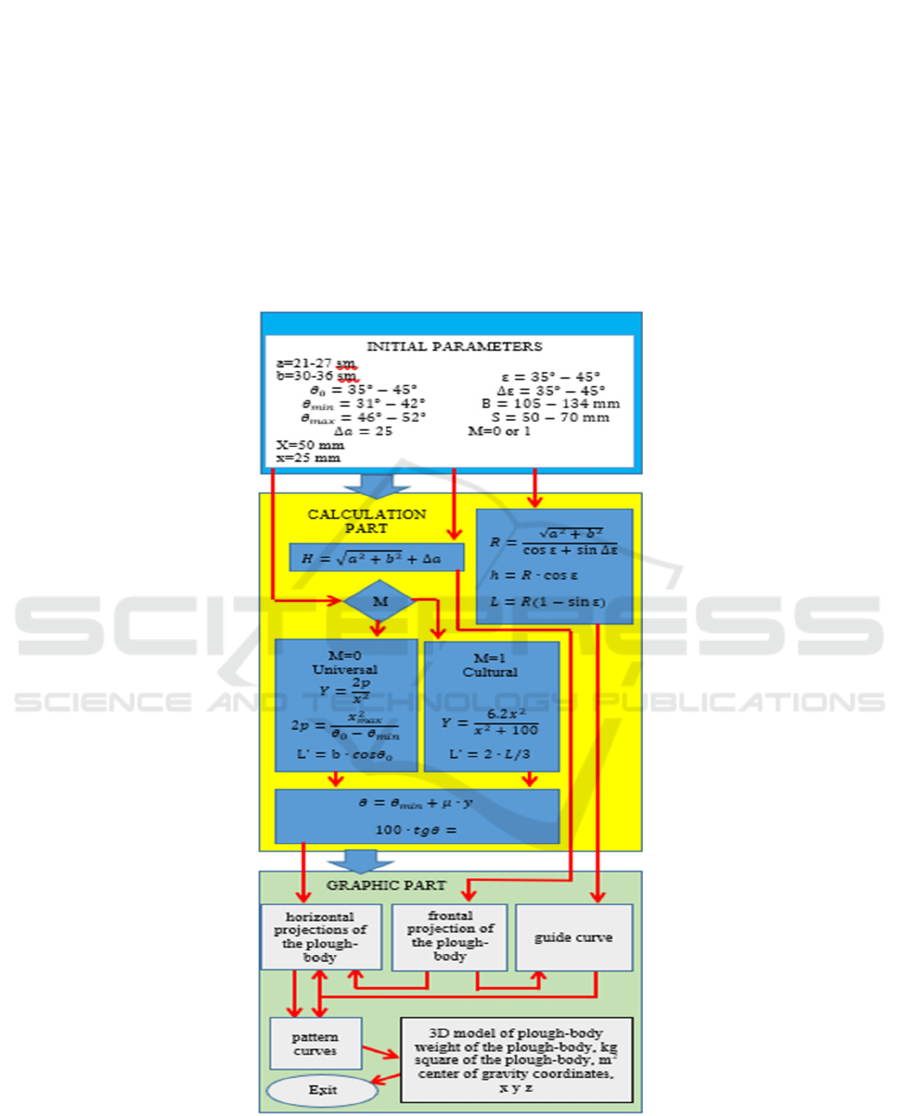
Figure 1: Block diagram of algorithm for parametric modeling of the plough-body.
Parametric Modeling in CAD Programs for Plow Design
183
3 RESULTS AND DISCUSSION
To create an automatic design program for the
plough-body, we can use the KOMPAS 3D program,
which is part of the CAD software.
Sequence of creating an automatic design
program
1. The parametric mode command is
launched in the drawing section of the KOMPAS
3D program;
2. Using the change command in the drawings
section of the KOMPAS 3D program, enter the
specified parameters and formulas used in the design
(Fig. 1). In the drawings section of the
KOMPAS;
3D program, the dimensions of each line used in
the design of the plough-body are entered into
functional connections using specified parameters or
directly specified parameters;
4. We create new working documentation through
the “Create” department for the design of the plough-
body in the KOMPAS 3D program;
5. To create the plough-body, use the commands
in the Frame and surfaces section;
6. This command creates parallel planes by
entering the distance between the planes;
7. In the process of designing a plough-body
based on design rules, we use pattern curves, where
each pattern curves is placed on parallel planes;
8. At the next stage, we connect the curves of the
model using the commands “Surface truncation”
and “Surface along a network of curves” and
create the working surface of the plow body.
9. The thickness of the surface is added to the
resulting working surface using the Fiberboard
Add Thickness command and a 3D model of the plow
body is created.
Table 1: Table of entered and received results.
Initial parameters
Mouldboard t
yp
e Cultural Universal
Working width 0.36 metr 0.32 metr
Plowin
g
de
p
th 0.25 met
r
0.22 met
r
ϴ
0
37º 41º
Obtained parameters
Weight 10.067 kg 13.098 kg
S
q
uare 0.375 m
2
0.495 m2
Center of gravity coordinates x=127.564 mm
y=484.109 mm
z=99.684 mm
x=167.564 mm
y=514.109 mm
z=130.684 mm
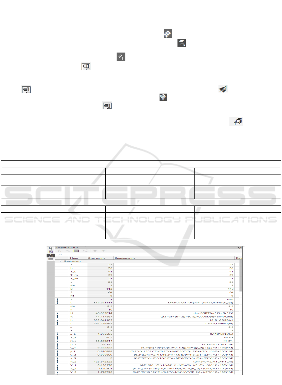
Figure 2: Entering parameters using the variables command.
I-CRAFT 2024 - 4th International Conference on Research of Agricultural and Food Technologies
184
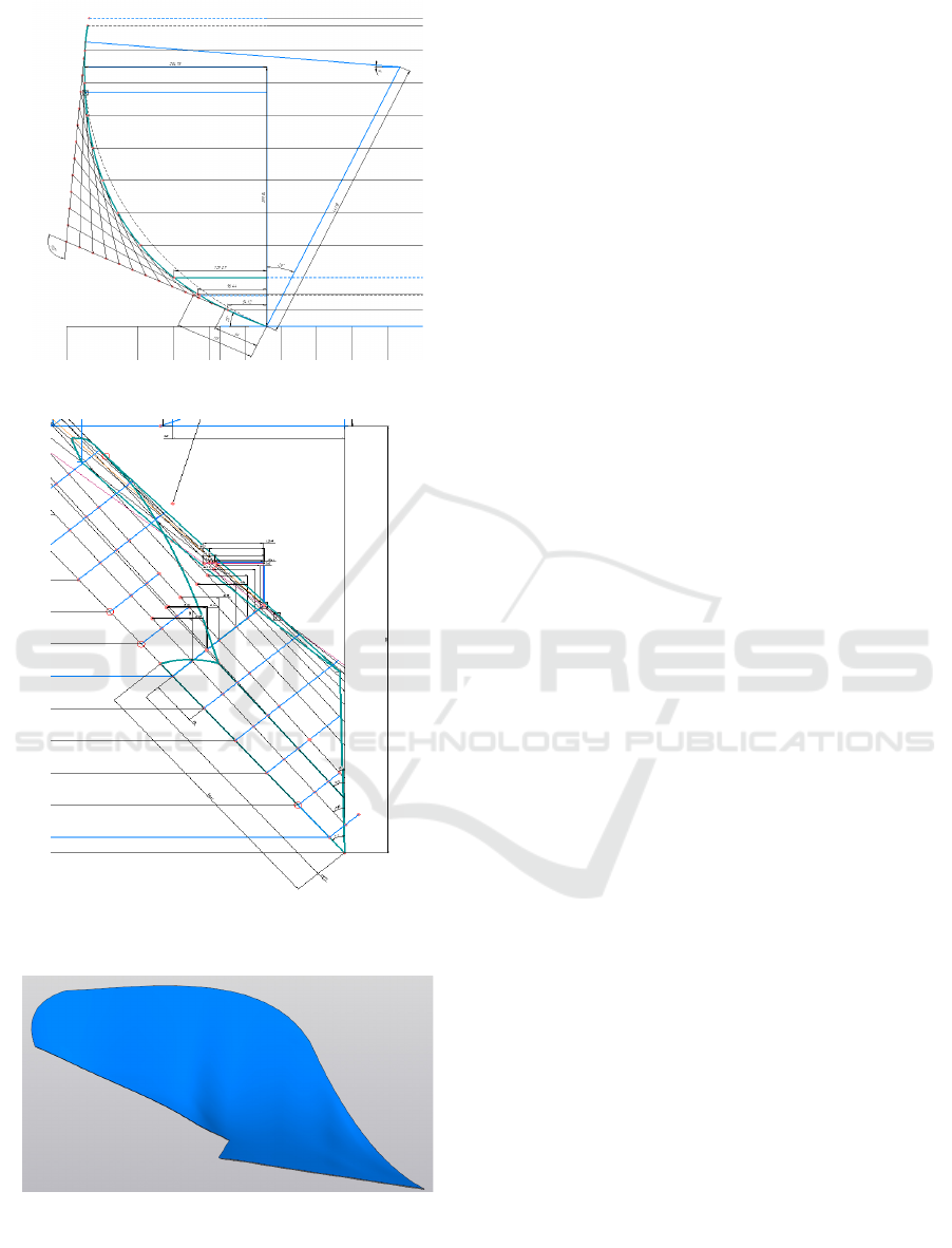
Figure 3: Construct of guide curve.
Figure 4: Construct of horizontal projection of mould board
when M=0.
Figure 5: Model of the plough-body obtained as a result of
using a computer-aided design program.
4 CONCLUSIONS
By learning deeply about computer-aided design
systems, other types of functionally related design
processes can be easily automated.
Through an in-depth study of parametric modeling in
CAD programs, it is possible to automate complex
design processes with other types of functional
connections, determine metal consumption in
advance and select the appropriate type of production
for the project.
As parametric modeling becomes more important in
the latest CAD programs, this method remains an
important part of the design editor with advanced
features for design acceleration, automatic updates
and feature monitoring.References
REFERENCES
Alimova, F., Saidova, M., Boboniyozov, E., & Mirzayev,
B., 2024. Analysis of the state of mechanized sowing of
rice in seedlings. BIO Web of Conferences, I-CRAFT-
2023 85 https://doi.org/10.1051/bioconf/20248501032
Alimova, F.A., 2023. Mathematical modeling of small soil
channel laboratory stand drive and evaluation of its
energy state - ETESD-II-2023 IOP Conf. Series: Earth
and Environmental Science 1284, 012031 IOP DOI:
10.1088/1755-1315/1284/1/012031.
Azimov, B.M., Sulyukova, L.F., Akhmedov, Sh. A.,
Azimov, M.B., 2020. Article name. International
Journal of Mechanical and Production Engineering
Research and Development (IJMPERD), 10(3): 4953–
4962.
Blednykh V.V., Khudyakov S.A., 1989. Mathematical
model of the working surface of the plow body.
Technology in Agriculture, 2: pages?.
Hedau, J., Dixit, S., Dhurde, T., Gharatkar, N., Shende, R.,
2023. Design and Fabrication of Multipurpose
Agricultural Machine: View Certificate.
https://doi.org/10.22214/ijraset.2023.50922
Jagtap, G., Bhade, T., Gade, P., Gonsalves, W., Bharati,
G.K., 2021. Design and fabrication of rice
transplantation machine. International Journal of
Creative Research Thoughts (IJCRT), 9(5): d358-360.
Juraev, T.K., Murodov, N.M. & Naimov, S. T., 2019.
Application the Geometric Modeling Methods and
Systems in Design Engineering and Manufacturing on
Example of Agriculture Engineering. Design and
Manufacturing, DOI: 10.5772/intechopen.89974
Makarova, E.I., 2000. Modeling the surface of the working
body of a soil-cultivating and sowing implement. Topic
of the dissertation and abstract on the Higher
Attestation Commission of the Russian Federation
05.20.01, Candidate of Technical Sciences
Maslov, G.G., 2019. Optimization of parameters of a multi-
functional unit based on a spring harrow. International
Parametric Modeling in CAD Programs for Plow Design
185

Journal of Engineering and Advanced Technology,
9(1): 1915-1918
Primkulov B.Sh., Boboniyozov E.A., 2022. Guidelines for
practical exercises in “automated design”. -Tashkent:
ToshDTU, 32.
I-CRAFT 2024 - 4th International Conference on Research of Agricultural and Food Technologies
186
