
Analysis of Operational Load of Flat-Parallel Moving Movable
Frame of Cotton Harvesting Apparatus
Ulugbek Saytov
a
, Anvar Abdazimov
b
and Bakhtiyor Azimov
c
Tashkent State Technical University, 100095, University str. 2, Tashkent, Uzbekistan
Keywords: Movable Frame, Cotton Harvesting, Plane-Parallel Dynamics.
Abstract: The article provides a brief description and a basic diagram of a new flat-parallel moving movable frame of a
vertical-spindle cotton harvesting apparatus. The nature of the forces acting on the frame is analyzed taking
into account changes in the design of the suspension of the movable sections on the frame by the suspension
and the drive of the spindle drums and brush pullers. Calculation schemes of the new design of the movable
frame under the action of reaction forces from the interaction of the frame with the surfaces of the bed, with
elements of cotton bushes, inertial and load forces of the drive elements of the working bodies are developed.
Based on the developed calculation schemes, equations of the forces acting on the flat-parallel moving
movable frame with a new design of the suspension are compiled.
1 INTRODUCTION
The process of economic modernization in the
Republic of Uzbekistan shows the further
advancement of society towards liberalization,
expressed in the transformation of economic relations
and the formation of an innovative model for the
development of the country's economy. Today, as a
result of the rapid development of the "new
economy", the strengthening of the connection
between the capital market and new technologies, the
increase in their mobility and the growth in the scale
of the creation and use of knowledge, technologies,
products, services, real conditions have arisen for
solving the tasks set in the Development Strategy for
five priority areas of development of the Republic of
Uzbekistan in 2017-2021 (Decree of the President of
the Republic of Uzbekistan PF-4947, 2017). The
place of a given country in the world economic
community, its level of competitiveness in the world
arena of countries significantly depends on the system
of formation of new knowledge and technologies. It
should be noted that 80-95% of the growth of GDP of
developed countries of the world falls on knowledge-
intensive industries implementing innovations for
their development, in other words, in these countries
a
https://orcid.org/0009-0004-5502-2095
b
https://orcid.org/0000-0003-2846-2736
c
https://orcid.org/0009-0000-5600-4033
the innovative economy is widely developing (Decree
of the President of the Republic of Uzbekistan UP
3416, 2017).
Agricultural engineering of the Republic of
Uzbekistan is one of the key industries and is focused
mainly on the production of tractors and machines for
cultivating and harvesting cotton and has great
potential for exporting them to neighboring and
distant countries. Currently, there are 18 enterprises
operating in it, including 5 joint-stock companies
(JSC), 13 joint ventures (JV) with leading global
companies such as CNH, CLAAS, Lemken, John
Deere, etc. (Matchanov, 2023). Domestic semi-
mounted vertical-spindle (VS) cotton harvesting
machines (CHM) on a tractor, manufactured by JSC
TTP, are inferior in productivity and completeness of
harvesting to American self-propelled horizontal-
spindle (HS) machines. But it is not profitable for
farms to purchase an expensive self-propelled CHM,
which operates only 20-30 days a year. They find it
convenient and profitable to use a mounted or semi-
mounted CHM, the power source (tractor) of which
can be used during the year for other agricultural
work. According to calculations by Research Institute
of Agricultural Mechanization Uzbekistan, the
efficiency of a mounted CHM is twice as high as that
12
Saytov, U., Abdazimov, A. and Azimov, B.
Analysis of Operational Load of Flat-Parallel Moving Movable Frame of Cotton Harvesting Apparatus.
DOI: 10.5220/0014041300004738
Paper published under CC license (CC BY-NC-ND 4.0)
In Proceedings of the 4th International Conference on Research of Agricultural and Food Technologies (I-CRAFT 2024), pages 12-17
ISBN: 978-989-758-773-3; ISSN: 3051-7710
Proceedings Copyright © 2025 by SCITEPRESS – Science and Technology Publications, Lda.
of a self-propelled one (Khojiev et al., 1994). The
comparatively low cost and operating costs of the
semi-mounted VS CHM, high selective capacity for
crop maturity and the ability to harvest at 55-60% boll
opening, as well as the ability to quickly (in 2-3
hours) mount it on a tractor and dismount it after the
end of the harvesting season for use in other
agricultural work, determine their potential not only
for Uzbekistan and the countries of Central Asia, but
also for other cotton-producing countries in the
northern belt, starting to harvest at a low boll opening
(Abdazimov et al., 2011).
One of the factors reducing the technical level of
serial semi-mounted tractors VS CHM series MX is
the insufficient stability of technological adjustments
(width of the working gap, staggered arrangement of
the spindles of adjacent drums) of the harvesting
apparatus (HA), resulting from the failure to improve
the design of the frame and drive of the spindle drums
of the movable section (Abdazimov et al., 2014), is
that when changing the width of the working gap HA,
the staggered arrangement of the spindles of adjacent
drums is disrupted, leading to deterioration of the
agrotechnical indicators (ATI) of the CHM. In this
case, the magnitude of the disruption of the staggered
arrangement of the spindles of adjacent drums
consists of two components - from a change in the
position of the frame of the movable section in space
and from an additional rotation of the spindle drum of
the movable section due to the presence of a dog
(tooth-lever) mechanism for driving the drums of the
movable section. That is, the division of the HA into
movable and fixed sections and the presence of a
gear-lever (drive) mechanism in the drive design and
ensuring the width of the working gap by moving
only one outer section, during which additional turns
of the spindle drum of the movable section occur, lead
to a violation of the staggered arrangement of the
spindles of adjacent drums and, as a consequence, to
a deterioration in the quality and reliability of the
machine.
The above-mentioned shortcomings have been
eliminated in the new design of the cotton harvesting
apparatus movable frame developed at the
Department of Ground Transport Systems at Tash
STU (Abdazimov et al., 2021), the diagram of which
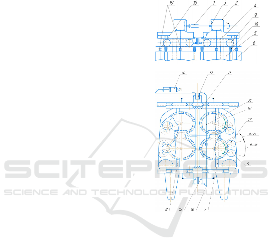
is shown in Figure 1, a-front view, b-top view.
In the new design of the movable frame of
sections (Abdazimov et al., 2021), the drive of the
spindle drums 5 and strippers 6 (see Fig. 1, a and b)
of the movable frames of sections 7 and 8 is carried
out using bevel 3 and cylindrical gears 4 located in
the reducer 2. The reducers of the left 7 and right 8
movable sections are connected to each other by an
inter-section splined cardan shaft 1.
а
b
Figure 1: Schematic diagram of a cotton harvesting
apparatus with plane-parallel moving movable frames.
The movable frames of the section contain rollers
9, by means of which they can move on the transverse
bars of the guides 10 of the apparatus frame, are
pulled together by springs 11 and symmetrically
plane-parallel move apart relative to the axis of the
cotton row when their projections with rollers 13 of
the cams 12 of the working gap adjustment
mechanism act on them, containing a hydraulic
cylinder 14, kinematically connected by a rod 15 and
a lever 16 of the axis of the cams 12. To increase
reliability and reduce energy consumption, the bevel
and cylindrical transmissions of the reducer of the
movable section are made helical. To ensure
maintainability and technical maintenance, the shafts
in the working members - spindle drums 5 and
strippers 6 are made composite - part in the reducer
with drive gears, the other part in the working
Analysis of Operational Load of Flat-Parallel Moving Movable Frame of Cotton Harvesting Apparatus
13
members and are connected to each other by sleeve
couplings 19. If technical maintenance or repair is
necessary, the said working members can be
dismantled from the movable section by removing the
couplings.
Due to the changes made in the design of the
suspension of the movable frames on the frame and
the drive of the working bodies (the exclusion from
the design of the vertical hinged suspension of the
movable frame to the frame and the toothed-lever
mechanism of the drive), the stability and reliability
of the technological adjustments of the HA are
ensured, which contributes to an increase in the ATI
and productivity of the CHM. The purpose of this
work is to develop theoretical and experimental
foundations for substantiating the main parameters of
the new design of the movable section of the cotton
harvesting apparatus, taking into account its
operational load in real conditions. For this purpose,
an analysis of the forces acting on the movable frame
during the operation of the machine in cotton rows is
necessary.
2 MATERIALS AND METHODS
When the HA is operating in the field, the following
forces act on the movable frame (Fig. 2):
1. Inertial forces - 𝑚
х, 𝑚
𝑦, 𝑚
𝑧 and 𝑚
с
х,
𝑚
𝑦, 𝑚
с
𝑧, which act on the frame through the upper
and lower supports of the spindle and removable
drums, and the forces 𝑚
𝑧 and 𝑚
с
𝑧 only through
the upper supports (since the outer races of the
bearings of the drum shaft supports are seated in
supports with a sliding fit, which allows the lower
ends of the drum shafts to move relative to the lower
rods of the frame, and the upper part of the drum
shafts is stationary in the vertical direction relative to
the upper beam of the frame). These forces arise at
the center of gravity of the spindle and removable
drums during oscillations of the cleaning apparatus on
the suspension mechanisms.
2. The weights of the spindle 𝐺
and removable
𝐺
с
drums, which are applied to the upper supports of
the drums (the weight forces of the gear blocks were
neglected due to their insignificance).
3. Bush pressures 𝑁
(
𝑡
)
, directed perpendicular
to the xoz plane and transmitted to the upper and
lower supports of the spindle drums.
4. Compression springs 𝑃
х
, 𝑃
у
, 𝑃
and 𝑃
х
,
𝑃
, 𝑃
transmitted to the frames.
5. Soil pressures 𝑃
х
and 𝑃
(Fig. 3, a), acting on
the lower front part of the frame. These forces arise
due to the unevenness of the furrow, when driving
over ditch-irrigations with lowered devices, etc.
6. Soil pressure on the lower frame rod. These
forces arise due to the interaction of the lower surface
of the frame with the soil during the process of
harvesting raw cotton (Fig. 3, b).
7. Soil pressure on the lateral surface of the lower
frame rod (not shown in Fig. 2 and 3). Lateral forces
arise due to the interaction of the lateral surface of the
lower frame with the bed when the CHM exits onto
the headland with lowered devices.
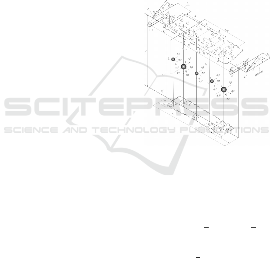
Figure 2: Diagram of forces acting on the movable frame of
the HA.
To determine the inertial forces 𝑚
х , 𝑚
𝑦 , 𝑚
𝑧
and 𝑚
с
х , 𝑚
𝑦 , 𝑚
с
𝑧 , it is necessary to
experimentally establish the values of the
accelerations х, 𝑦, 𝑧 of the center of gravity of the
apparatus during its oscillations. Then the actions of
the latter on the supports are determined from the
following relationship (see Fig. 2).
𝑃
.
х
=±𝑚
х(
1−
𝑙
ц
𝑙
), 𝑃
н.
х
=±𝑚
х
𝑙
ц
𝑙
,
𝑃
.
=±𝑚
𝑦(
1−
𝑙
ц
𝑙
),
𝑃
н.
=±𝑚
𝑦
ц
, 𝑃
.
=±𝑚
𝑧 +𝐺
𝑙
where l
n
is the distance between the supports of the
spindle drums and pullers.
I-CRAFT 2024 - 4th International Conference on Research of Agricultural and Food Technologies
14

The bush pressure is determined by the formula
(Glushchenko, 1985):
𝑁
(
𝑡
)
=
∑
𝑁
,
𝑐𝑜𝑠𝑖𝜔
𝑡, (1)
where 𝑁
− amplitude of the “i” harmonic;
𝜔
=
𝑖
− number of the last harmonic taken into
account;
𝑉
− driving speed of the CHM;
𝑆
− average distance between adjacent cotton nests
(𝑆
depends on the planting pattern of the bushes).
The forces of the tension springs are equal
𝑃
=𝑘
∆𝑙
и 𝑃
=𝑘
∆𝑙
,
where 𝑘
and 𝑘
− spring stiffness coefficients,
respectively, ∆𝑙
and ∆𝑙
− deformations of the
springs accordingly.
The projections of the forces of the tension springs on
the x, y, and z axes will be equal to (Fig. 2)
(Abdazimov et al., 2022):
𝑃
х
=𝑃
𝑠𝑖𝑛𝛽
, 𝑃
у
=𝑃
𝑐𝑜𝑠𝛼
, 𝑃
=
𝑃
𝑠𝑖𝑛𝛼
𝑃
х
=𝑃
𝑠𝑖𝑛𝛽
, 𝑃
=𝑃
𝑐𝑜𝑠𝛼
,
𝑃
=𝑃
𝑐𝑜𝑠𝛼
. (2)
The force of soil pressure on the front part of the
lower frame is determined by the formula (Handbook,
1968):
𝑃
= 𝜀𝜌𝑎ℎ𝑣
(3)
where ε – dimensionless coefficient depending on the
frame shape and soil properties;
ρ – soil density, kg/m
3
;
υ – driving speed of the cotton harvesting apparatus,
m/s;
h – height of soil unevenness;
a – rod width;
𝛼− rod elevation angle.
The projections of the soil pressure force 𝑃
on the x
and z axes are equal to
𝑃
х
=𝑃
𝑠𝑖𝑛𝛼 𝑃
п
=𝑃
𝑐𝑜𝑠𝛼, (4)
The pressure of the soil on the lower and lateral
surfaces of the lower frame rod can be replaced by a
uniformly distributed load applied along the length of
the lower frame rod, i.e.
а b
Figure 3: Scheme of the action of soil pressure on frames
when moving a CHM across an arrow ditch with lowered
devices
𝑁=𝑓∙𝑃
(5)
where f – coefficient of friction;
a – height of the lower rod (see Fig. 2).
To determine the forces from the gear transmissions
acting on the frame, let us consider the drive diagram
of the spindle and removable drums of the HA with a
new design of the movable section (Abdazimov et al.,
2021).
To determine the load on the shaft or on the
cantilever axis, it is necessary to draw a diagram for
each drive gear. Fig. 4 shows a diagram for
determining the loads on the spindle and removable
drums and on cantilever axles of parasitic gears.
Figure 4: Scheme for determining loads from gear
transmissions.
Analysis of Operational Load of Flat-Parallel Moving Movable Frame of Cotton Harvesting Apparatus
15

Considering that the values of torque on the
spindle shafts and removable drums are known, we
determine the values of torque on the drive gears:
𝑀
=𝑀
, 𝑀
=
, 𝑀
=
+
𝑀
ш
, 𝑀
=
+
, 𝑀
=
+
𝑀
ш
, (7)
𝑀
=𝑀
, 𝑀
=
, 𝑀
=
,
where 𝑀
and 𝑀
ш
are the torques on the shafts of the
removable and spindle drums.
Let us consider the action of the 𝑍
puller gear on
the 𝑍
gear block gear. The action of the 𝑍
gear on
the 𝑍
gear is replaced by the force 𝑃
∙
, directed
along the engagement line “ab” (see Fig. 4.).
The total pressure on the tooth is determined by
the formula
𝑃
∙
, (8)
where 𝑀
− torque on puller shaft 8;
𝐷
− diameter of the pitch circle of the gear
𝑍
;
𝛼 = 20° −
engagement angle.
Since gear 𝑍
of the gear block rests on axis 6, the
action of gear 𝑍
on this axis can also be replaced by
force 𝑃
∙
.
Similarly, we get
𝑃
∙
=
, 𝑃
∙
=
, 𝑃
∙
=
, (9)
𝑃
∙
=
, 𝑃
∙
=
, 𝑃
∙
=
, 𝑃
∙
=
.
The projections of these forces along the Y and X
axes will be equal to
𝑃
∙
=𝑃
∙
𝑠𝑖𝑛𝛾
, 𝑃
∙
=
𝑃
∙
𝑐𝑜𝑠𝛾
, 𝑃
∙
=𝑃
∙
𝑡𝑔𝛼 ,
𝑃
∙
=𝑃
∙
𝑐𝑜𝑠𝛼 , 𝑃
∙
=𝑃
∙
𝑡𝑔𝛼 ,
𝑃
∙
=𝑃
∙
𝑐𝑜𝑠𝛼 ,
𝑃
∙
=𝑃
∙
𝑐𝑜𝑠𝛾
, 𝑃
∙
=
𝑃
∙
𝑠𝑖𝑛𝛾
, 𝑃
∙
=𝑃
∙
𝑐𝑜𝑠𝛼, (10)
𝑃
∙
=𝑃
∙
𝑡𝑔𝛼, 𝑃
∙
=𝑃
∙
𝑐𝑜𝑠𝛾
,
𝑃
∙
=𝑃
∙
𝑠𝑖𝑛𝛾
,
𝑃
∙
=𝑃
∙
𝑡𝑔𝛼 , 𝑃
∙
=
𝑃
∙
𝑐𝑜𝑠𝛼 , 𝑃
∙
=𝑃
∙
𝑐𝑜𝑠𝛾
,
𝑃
∙
=𝑃
∙
𝑠𝑖𝑛𝛾
,
where 𝛾
=𝛽
−𝛼; 𝛾
=𝛽
−𝛼; 𝛾
=𝛽
−
𝛼; 𝛾
= 90°− (𝛽
+𝛼).
The obtained expressions of forces acting on the
movable frame are typical for the static mode. In the
dynamic mode, the load of the movable frame of the
cotton harvesting apparatus section as such has not
been studied as a whole. Although the dynamics of its
working elements, such as spindles, spindle and
stripper drums, as rotation units were studied in
sufficient detail in the works (Glushchenko, 1985;
Glushchenko, 1990; Turanov, 1989). Analytical
expressions of bending, torsional, pendulum and axial
oscillations of the spindle, bending and torsional
oscillations of the spindle drum shaft and the stripper
shaft were obtained, approximate methods for solving
systems of equations describing the specified
processes were proposed. Calculation and
experimental studies have established that the
working elements of the drum-type CHM themselves
are sources of excitation of dynamic loads, leading to
the failure of individual connections of the parts of
these working elements due to their design
imperfections (Turanov, 1989). The specified loads
are transferred to some extent by the frames that carry
them, but their values in relation to technological ones
(impacts from the surfaces of the ridges of the bed and
the bush mass in the row) are significantly less
(Turanov, 1989). Consequently, it is of great
importance to determine the values of external
impacts on the movable frame under operating
conditions.
3 RESULTS AND DISCUSSION
The obtained expressions of forces acting on the
movable frame are typical for the static mode. In the
dynamic mode, the load of the movable frame of the
cotton harvesting apparatus section as such has not
been studied as a whole. Although the dynamics of its
working elements, such as spindles, spindle and
stripper drums, as rotation units were studied in
sufficient detail in the works (Glushchenko, 1985),
(Glushchenko, 1990), (Turanov, 1989). Analytical
expressions of bending, torsional, pendulum and axial
oscillations of the spindle, bending and torsional
I-CRAFT 2024 - 4th International Conference on Research of Agricultural and Food Technologies
16

oscillations of the spindle drum shaft and the stripper
shaft were obtained, approximate methods for solving
systems of equations describing the specified
processes were proposed. Calculation and
experimental studies have established that the
working elements of the drum-type CHM themselves
are sources of excitation of dynamic loads, leading to
the failure of individual connections of the parts of
these working elements due to their design
imperfections (Abdazimov et al., 2022). The
specified loads are transferred to some extent by the
frames that carry them, but their values in relation to
technological ones (impacts from the surfaces of the
ridges of the bed and the bush mass in the row) are
significantly less (Handbook, 1968). Consequently, it
is of great importance to determine the values of
external impacts on the movable frame under
operating conditions.
4 CONCLUSIONS
The conducted studies substantiated the methodology
for drawing up calculation schemes for determining
the loads acting on the elements of the new HA
structures with plane-parallel moving movable
frames. The developed calculation methodology
allows determining the values of bending and torque
moments in the sections of movable frames taking
into account individual values determined based on
the results of planned experiments.
REFERENCES
Abdazimov A.D., Atajanova M.M., Azimov B.M. and
Saytov U.A.. Modelling movement of pull-up spring of
cotton harvesting apparatus. AEGIS-2022 IOP Conf.
Series: Earth and Environmental Science 1076 (2022)
012004 doi:10.1088/1755-1315/1076/1/012004.
Abdazimov A.D., Sadriddinov A.S. Ulzhaev E. et al.
Movable frame of a section of a vertical-spindle cotton
harvesting apparatus. Patent for Utility Model No. FAR
01580 dated 09.02.2021.
Abdazimov A.D., Sadriddinov A.S., Tulyaev A.R. Phase
discrete modeling of processes in harvesting devices
with controlled movement of cotton bolls. Tashkent:
Publishing house of the National Library of Uzbekistan
named after A. Navoi, 2011, -180 p.
Abdazimov A.D., Ulzhaev E., Ubaydullaev U.M., Omonov
N.N. Fundamentals of automation of control and
management of technological parameters of cotton
harvesting machine. Tashkent: TashSTU, 2014, -164 p.
Decree of the President of the Republic of Uzbekistan PF-
4947 of February 7, 2017 “On the development strategy
in five priority areas of the Republic of Uzbekistan in
2017-2021”.
Decree of the President of the Republic of Uzbekistan UP
3416 of November 30, 2017 “On the formation of the
Ministry of Innovative Development of the Republic of
Uzbekistan”.
Glushchenko A.D. Dynamics of Drive Mechanisms of
Spindle Drives of Cotton Harvesting Machine
Harvesting apparatuss. Tashkent: Fan, 1985, -154 p.
Glushchenko A.D., Tashboltayev M.T. Dynamics of
Rotation Units of Cotton Harvesting Machine
Harvesting apparatuss. Tashkent: Fan, 1990, -138 p.
Handbook of the designer of agricultural machinery. Edited
by Candidate of Technical Sciences M.I. Kletskin.
Moscow: Mechanical Engineering, 1968. – 744 p.
Khojiev A., Norkulov S., Pavlov G., Khakimov A. What
are machines capable of? // “Khalk sozi” newspaper,
September 2, 1994.
Matchanov R. D. Chronicle of domestic agricultural
machinery. Tashkent: “Zamin nashr”, 2023, -334 p.
Turanov H.T. Dynamics of Working Bodies of Drum-Type
Cotton Cleaning and Cleaning Machines. Tashkent:
Fan, 1989, -112 p.
Analysis of Operational Load of Flat-Parallel Moving Movable Frame of Cotton Harvesting Apparatus
17
