
Improvements in the Performance of Silicon-Based Anode Materials
for Lithium-Ion Batteries
Leirun Chen
College of Materials Science and Engineering, University of Jinan, Jinan, Shandong, 250000, China
Keywords: Lithium-Ion Batteries, Silicon Anode Materials, Structure Optimization, Composite Materials.
Abstract: Lithium-ion batteries (LIBs) have emerged as the preferred choice for electric vehicles (EVs) owing to their
lightness, prolonged lifespan, and superior energy density. Despite graphite's prevalent use as the anode
material in the commercial LIB, its limited specific capacity poses challenges in satisfying the escalating
energy storage requirements. As a result, high-energy anode materials for LIBs are prioritized. The silicon
anode materials have received widespread praise because of their high specific capacity. Still, the structural
alterations and growth in volume of silicon anode materials throughout both charging and discharging
processes severely restrict their practical uses. Through structural optimization and composite modification
of silicon anode materials, their electrochemical performance can be effectively enhanced, which is crucial
for the creation of high-energy LIBs. This paper systematically reviews the research progress of the silicon
anode and its composite materials in terms of structure optimization, composite modification, and energy
storage performance at this stage. It looks forward to the future development patterns of such materials.
1 INTRODUCTION
In the twenty-first century, the continuous growth of
global energy demand and the urgency of
environmental protection issues have driven the
energy transition to clean energy sources such as
electricity. In this transition, the rise of new energy
vehicles, especially electric vehicles (EVs), not only
offers a fresh approach to addressing the issues of
energy depletion and environmental pollution but
also promotes the rapid development of related
technologies. Compared with traditional fuel
vehicles, the environmental advantages of new
energy vehicles are particularly significant. Driven by
electricity, they significantly reduce CO
2
emissions,
helping to alleviate the pressure of global warming.
At the same time, new energy vehicles run more
quietly, significantly reducing urban noise pollution
and providing a more liveable environment for
residents. However, new energy vehicles are not
perfect. Although they have many advantages such as
environmental protection, energy saving, and high
efficiency, issues such as range and safety are still
challenges. To overcome these challenges,
innovations in battery technology have become
crucial. Because of its outstanding energy density and
prolonged cycle life, lithium-ion batteries (LIBs)
currently hold the top spot in the batteries used in
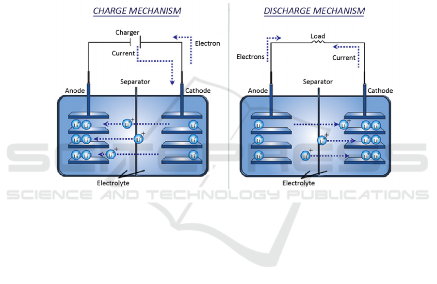
EVs. This kind of battery realizes the efficient
conversion of electrical energy and chemical energy
by shuttling Li
+
between the cathode and anode (as
shown in Figure 1), and its main structure includes the
cathode, anode, electrolyte, and diaphragm. Among
them, the anode material is a key factor affecting its
performance.
The traditional carbon anode material has better
stability, but its theoretical specific capacity is
limited, making it difficult to meet the demand for
high-capacity batteries in EVs. Since silicon anodes
can have a specific capacity of 3580 mAh/g, they are
highly respected. Additionally, silicon is thought to
be a viable anode material for LIB with a high energy
density because it is abundant in nature,
environmentally friendly, and has a good
electrochemical potential.
Nevertheless, there are several fatal drawbacks of
silicon material as anodes for LIBs. First, during
charging, the silicon anode undergoes an alloying
reaction with lithium, resulting in an expansion of the
electrode volume by about 300%. The silicon anode
is ground up and an unstable solid electrolyte
interface (SEI) is created as a result of this expansion,
leading to the active material and collector losing
their electrical connection, which makes it harder for
Li
+
to be embedded and eventually reduces capacity
218
Chen, L.
Improvements in the Performance of Silicon-Based Anode Materials for Lithium-Ion Batteries.
DOI: 10.5220/0013878500004914
Paper published under CC license (CC BY-NC-ND 4.0)
In Proceedings of the 2nd International Conference on Renewable Energy and Ecosystem (ICREE 2024), pages 218-223
ISBN: 978-989-758-776-4
Proceedings Copyright © 2025 by SCITEPRESS – Science and Technology Publications, Lda.
and initial Coulombic efficiency. Furthermore, the
silicon anode's expansion increases the electrode
surface area, necessitating more Li
+
consumption to
form the SEI film, causing a decrease in battery
capacity. In addition, the diffusion coefficient of Li
+
in silicon is not high, ranging from 10
-14
to 10
-13
cm²/s,
a property that results in a large Li
+
concentration
gradient in silicon, which generates large internal
stresses during cyclic charging and discharging,
ultimately leading to fragmentation of silicon
particles. Meanwhile, the low conductivity of silicon
tends to electrically insulate the crushed silicon
particles, which in turn affects the capacity of the cell
and results in a significant loss of capacity.
To overcome these challenges, researchers are
actively exploring various modification methods.
They do so by designing rational silicon anode
structures, introducing buffer layers or composites,
and other techniques, to enhance the performance of
silicon anodes. Thus, this paper examines and
evaluates the research advancements of silicon anode
materials for LIBs, and anticipates future research on
silicon anode materials.
Figure 1: Schematic diagram of the operating principle of a LIB (Omar et al., 2012).
2 TYPES AND ADVANTAGES
AND DISADVANTAGES OF
LIBS ANODES
2.1 Nanosilicon Anode
The diffusion time of Li
+
in the electrode is jointly
influenced by the diffusion coefficient (D
Li
),
diffusion length (L) and the natural characteristics of
the material. Equation 1 shows that by drastically
lowering the particle dimension, the nanosizing
technology may greatly shorten the Li
+
diffusion
length, increasing power density and mechanical
strain tolerance. Therefore, in order to solve the
particle fragmentation problem of silicon anode due
to the large Li
+
concentration gradient, silicon
nanostructures such as nanotubes (NTs), nanowires
(NWs), and nanofibres (NFs) have been widely used
to optimise the electrode structure and electrical
properties, especially silicon nanowires (SiNWs) and
nanotubes (SiNTs), which have a significant
reversible capacity exceeding 200 mAh/g, and exhibit
excellent cycling stability.
t=
L
2
D
Li
ൗ
(1)
Among the preparation methods of nanosilicon,
hydrothermal method is favoured due to its low cost,
environmental friendliness, and applicability to large-
scale production. Scientists have successfully
prepared high-purity nanosilicon by selecting
different silicon sources, such as (2-
aminoethylamino) propyltriethoxysilane and
tetraethyl orthosilicate (TEOS), in combination with
hydrothermal methods. In addition, rice husk, as an
agricultural waste in people's daily life, has a SiO
2
content as high as 10% to 20%, which not only
reduces the cost but also is environmentally friendly
and feasible as a silicon source for the production of
Improvements in the Performance of Silicon-Based Anode Materials for Lithium-Ion Batteries
219

nanosilicon. Currently, Sudarman et al. (2024) have
successfully prepared high purity nanosilicon by
hydrothermal method using rice husk, and this
nanosilicon works well as a LIB anode, exhibiting a
capacity of 1,757 mAh/g and continuing to do so after
approximately 200 cycles. Its energy density and
cycling stability surpass those of commercial
batteries, graphite, and graphene.
Nonetheless, the nanosilicon anode still suffers
from poor electrical conductivity and high
manufacturing cost, which limits its large-scale
industrial application. Therefore, future research
needs to further explore how to reduce the
manufacturing cost of nanosilicon anodes while
improving energy density and cycling stability, in
order to promote their widespread application in the
field of LIBs.
2.2 Silicon Alloy Anode
In the pursuit of enhancing the electrochemical
performance of silicon anode, in addition to adjusting
the dimension of silicon particles, another effective
method is to combine silicon with suitable metals
(e.g., Ni, Cu, Sn, Pb, Li, etc.) to form an alloy phase.
This alloying strategy takes advantage of the ductile
properties of metals to give silicon alloy composites
the ability to slow down the volume expansion of
silicon.
Firstly, silicon and lithium can form a variety of
alloys, such as Li
12
Si
7
, Li
13
Si
4
, Li
7
Si
3
, Li
15
Si
4
, Li
22
Si
5
,
etc., which not only have high capacity, but also have
de-embedded lithium potentials lower than 0.5 V vs.
Li/Li
+
, with Li
22
Si
5
having a capacity of up to 4200
mAh/g.
In addition to Si-Li alloys, there are other silicon-
based alloy materials. Mukanova et al. (2017)
achieved a facet capacity of 80 mAh/cm² by forming
a three-dimensional composite anode with silicon
thin films on graphene-coated nickel foam by
chemical vapour deposition and magnetron
sputtering. Ding et al. (2020) prepared a binder-free
anode with bilayer graphene-coated silicon
nanoparticles (SiNPs) embedded in the porous nickel
current collector, and although a respectable face
capacity was achieved, the performance of the
interfacial layer still needs to be improved. In view of
this, Tzeng et al. (2023) proposed thick and porous
silicon-based anodes, and constructed porous anodes
with electrical conductivity on nickel foam by mixing
SiNPs, phenolic resin binder, and the conductive
agent Super P, which exhibited excellent cycling
performance and charge storage capacity.
Experiments shown that the 80 nm nickel foam
nanoporous silicon-based anode maintained excellent
performance after a total of 50 cycles, where the
current density was 4 mA/cm
2
, retaining a retained
area capacity of up to 6.5 mAh/cm², which provided
a charge storage capacity of 23.4 C for an anode area
of 1 cm² at a current rate of 4 mA.
In particular, the eutectic reaction takes place
throughout the melting procedure because the melting
points of Cu and Si are slightly different. This makes
it simpler for Si to create the Cu
3
Si alloying phase and
evenly disperse it on the Si matrix resulting in greater
suppression of the volume growth. Zhang et al.
(2021) first prepared Si-Cu
3
Si composite with a
capacity of 1000 mAh/g after 300 cycles, while Li et
al. (2023) prepared P-doped Si-Cu alloys by the
vacuum melting method, which improve the electrical
conductivity and lower the Li
+
diffusion barriers to
significantly enhance the electrochemical
performance, Among these, the P
0.5%
Si-Cu alloy had
a significantly lower R
ct
value than the undoped Si-
Cu alloys, with a capacity of 1048 mAh/g after 60
cycles.
In addition, Si-Sn alloy anode has sparked much
interest because of its unique lithium embedding
ability and buffering effect on volume change. Tian
et al. (2021) successfully prepared a novel anode
material consisting of tin nanowires (SnNWs)
embedded with SiNPs by solid-gas reaction method,
which exhibited a high and stable capacity at both
room and low temperatures.
Although silicon alloy structure has significant
effect in solving the swelling problem of silicon-
based anode, its preparation process is complicated
and costly, which limits its mass production
application. Therefore, researchers have turned to the
strategy of compositing nanosilicon and carbon
materials to seek performance enhancement and cost
reduction.
2.3 Silicon-Carbon Composite Anode
In the field of LIBs, carbon anodes are known for
their high cycle life, while silicon anodes exhibit
excellent specific capacity. Based on this, scientists
have proposed to dope carbon atoms into a silicon
anode to obtain a LIB anode with high specific
capacity and long service life Therefore, researchers
have proposed a silicon carbon anode and achieved
their goal with the help of nanotechnology. Wu et al.
(2024) have found through their study that the volume
variation of silicon was successfully inhibited when
the doping concentration of carbon atoms was in the
range of 1.56% to 15.6%. This suppression effect is
attributed to the high strength of the Si-C covalent
ICREE 2024 - International Conference on Renewable Energy and Ecosystem
220

bond, which results in a denser structure of the
material and a consequent increase in bulk modulus.
In addition, the inhibition effect on the volume
expansion of silicon shows an enhanced trend as the
carbon concentration increases. Carbon compounds
come in a variety of forms, including graphite,
graphene (Gr), carbon nanotubes (CNTs), carbon
nanofibres (CNFs), graphene oxide (GO), reduced
graphene oxide (rGO), and so forth.
Graphene, renowned for its flexibility and
conductivity, mitigates silicon's volume changes,
enhances electron transfer, and isolates particles from
the electrolyte, suppressing excessive SEI formation.
Besides, its defects and edges provide additional sites
for lithium storage, accelerating Li
+
transport in the
anode and thus significantly improving the
multiplicity performance of the battery. However, it
is challenging to attain optimal dispersion via
straightforward mechanical mixing because of
graphene's neutral property. The introduction of GO
can effectively address the dispersion issue because
irregularly dispersed SiNPs are more likely to
undergo electrochemical sintering and agglomeration
throughout the charging and discharging process. So,
Ko et al.(2014) proposed the use of chemical vapor
deposition (CVD) technology to prepare porous GO
with silicon skeleton as an anode material for the LIB,
which significantly improved the cycle stability. The
material was tested to maintain an average capacity
of 1103 mAh/g after 1000 cycles with a Coulombic
efficiency of up to 92.5% on the first cycle. However,
CVD technology is expensive and not suitable for
large-scale industrialization.
Electrostatic spinning technology, on the other
hand, offers a simple and economical method of
preparing carbon fibres. As a result, silicon is often
embedded in carbon fibers as an anode material for
LIB. Gómez-cámer et al. (2011) utilized a SiO
x
layer
to strengthen the bonding of SiNPs to the CNFs
surface, which significantly enhanced the ion and
electron transport efficiency. However, this anode’s
capacity decayed from 2500 to 500 mAh/g after 500
cycles, due to excessive SEI formation and poor
stability. Ji et al. (2009), on the other hand, attempted
to convert the polyacrylonitrile/SiNPs solution into
SiNPs-embedded CNFs composites by
electrospinning, but the cycling stability dropped to
0.5 mAh/g, 51% of initial after 50 cycles, showing the
inadequacy of this method in suppressing the
generation of unstable SEI layers. Dirican et al.
(2015) went on to enhance the cycling stability by
depositing amorphous carbon on SiNPs-embedded
CNFs using the CVD method. However, the
aggregation of SiNPs and the problem of carbon fiber
fracture due to silicon swelling remain key challenges
to be addressed in this field.
Despite the high specific capacity and relatively
mature process of silicon-carbon composite
structures, their industrial production and cycling
performance still need to be further improved.
2.4 Yolk-Shell Structure Anode
While depositing SiNPs on the outer layer of carbon
materials can significantly improve the anode's
performance, the research on improving the LIB
anode's efficiency shows that each charge/discharge's
efficiency falls short of more than 99%. The reason
for this is that during the cycling process, a portion of
the silicon particles is near the fluid, causing the
particles to grow and shrink with each charge and
discharge. This prevents the SEI film from existing
steadily and causes it to be continually destroyed and
regrown. Therefore, the core-shell structure was born.
Despite the conventional core-shell design utilizing
silicon as the core with a carbon shell coating, it lacks
a buffer zone for silicon's volume expansion.
Consequently, researchers have innovated by
adopting a yolk-shell architecture, where silicon
serves as the yolk and carbon as the shell. This
approach introduces a gap between the carbon shell
and silicon particles, allowing for unconstrained
expansion and contraction of silicon while preventing
damage to the carbon shell due to volume variations
in the silicon particles. The anode designed by Liu et
al. (2012) is similar, which is shown in Figure 2. After
testing, yolk-shell anode demonstrated initial
capacity of 2800 mAh/g, retaining 74% (1500
mAh/g) after 1000 cycles, achieving 99.8%
Coulombic efficiency.
Figure 2: Structure of the yolk-shell type anode (Dirican et
al., 2015).
Liu et al. (2014) further optimized the previous
yolk-shell design in a follow-up study by adopting a
pomegranate-like layered architecture. This structure
featured SiNPs in a conducting carbon coating in a
yolk-shell-like configuration, and the entire structure
was encased in a thicker carbon shell at the micron
level. The strength of the SEI layer is increased by the
thicker carbon shell, which also has a significant
impact on the conductivity of electrons and Li
+
.
Durability testing revealed a capacity retention rate of
Improvements in the Performance of Silicon-Based Anode Materials for Lithium-Ion Batteries
221

97% and a Coulombic efficiency of 99.8% after 1000
cycles.
Yu et al. (2024), on the other hand, proposed a
Si@Void@FC (fiber carbon) composite structure.
This material simplifies the preparation process
through a one-step synthesis method and cleverly
combines a void yolk-shell structure with a
mesoporous carbon shell, which can exhibit excellent
cycling stability and outstanding rate performance,
and even after 500 cycles, the structure remained
intact without significant performance degradation.
This is so that excessive contact with the electrolyte
is avoided and the volume growth of silicon while
cycling is efficiently inhibited by the protective
coating that is the outside carbon shell. In addition,
the unique mesoporous structure significantly
improves the diffusion efficiency of Li
+
, which in turn
enhances the lithiation and de-lithiation ability of the
material.
In addition, Liu et al. (2024) pioneered the
concept of fluoride ion-modified yolk-shell-type
carbon-silicon anode materials. Through the
interfacial modification of fluoride ions, fluoride
components such as LiF were enriched in the SEI
membrane, which in turn significantly enhanced its
cycling stability. Experiments revealed that the F-
Si@Void@C anode can maintain a reversible
capacity of up to 1166 mAh/g after 900 cycles at a
current density of 0.5 A/g.
Although the yolk-shell structure is effective in
resolving the volume variation of Si anode throughout
charging and discharging, and it also enhances
Coulombic efficiency. However, the cost is still high,
and the preparation method can be subsequently
improved to achieve cost reduction.
3 OUTLOOK OF ANODE
MATERIALS FOR LIBS
In summary, the improvement technology of silicon-
based anode materials for LIBs has made rapid
development in the past few years, which effectively
solves the problem of volume variation of silicon-
based anodes when battery charging and discharging,
and improves the cycle life based on ensuring the
specific capacity. Therefore, with continuous
research, more and more novel improvement methods
of silicon-based anode will be discovered and
reported.
However, compared with other anode materials
for LIBs, Si-based anode has the problem of high
preparation cost. Therefore, designing more cost-
effective and environmentally friendly ways to
reduce costs while also enhancing the service life of
Si-based anode in accordance with the current
preparation process is unquestionably the direction of
key development for the future. Since silicon-based
anode materials are still in their infancy when
compared to graphite and other commercially
accessible anode materials, improving their cycle
stability, specific capacity, and cost reduction is
crucial for meeting the need for high-capacity LIBs in
the future.
4 CONCLUSION
In this paper, the modification methods of silicon
anode are summarized through a systematic review.
Firstly, in the nanosilicon anode, the diffusion time
was effectively reduced by shortening the diffusion
length, which significantly enhanced the power
density. Additionally, the small particle size particles
enhanced the mechanical strain adaptability and
successfully stopped the silicon volume expansion-
related mechanical failure. However, the capacity
degradation of silicon nanostructures remains to be
solved, mainly stemming from factors such as SEI
film formation, poor electrical contacts, and nano-
agglomeration. In order to address these challenges,
researchers have proposed combining silicon
nanostructures with other materials (carbon, metals)
to form anodes. Among them, silicon alloy anode can
slow down the volume expansion of silicon, but its
preparation process is complicated and costly.
Therefore, researchers have turned their attention to
compounding nanosilicon with carbon materials. The
carbon component of the silicon-carbon anode not
only acts as a barrier to stop the formation of unstable
SEI and as an effective transport channel for electrons
and Li
+
, but it also reduces silicon volume growth,
which is thought to be an exciting way to enhance the
performance of the silicon anode. On this basis,
researchers have proposed an improved method of
yolk-structured anode. In this anode, a carbon shell
layer acts as a barrier to form a void between the
silicon particles, allowing the silicon to expand and
contract freely without damaging the carbon shell.
Currently, there are still several issues to be
resolved. Firstly, the current cost of nanotechnology
is still high, and simple and economical preparation
methods are required to achieve nanoscale electrode
structures with excellent performance. Secondly, to
further explore theoretically how to enhance the
lithiation rate of silicon anodes in order to
manufacture LIB anode with improved performance,
ICREE 2024 - International Conference on Renewable Energy and Ecosystem
222

an extensive comprehension of the kinetics of silicon
lithiation is required.
REFERENCES
Ding X, Wang Y 2020 2020 Electrochim. Acta 329 134975.
Dirican M, Yildiz O, Lu Y, Fang X, Jiang H, Kizil H, Zhang
X 2015 Electrochim. Acta 169 52-60.
Gómez-Cámer JL, Morales J, Sánchez L 2011 J. Mater.
Chem. 21 811-818.
Ji L, Zhang X 2009 Carbon 47 pp 3219-3226.
Ko M, Chae S, Jeong S, Oh P, Cho J 2014. ACS Nano 8
8591-8599.
Li Q, Yu M, Huang Y, Cai Z, Wang S, Ma Y, Song G, Yu
Z, Yang W, Wen C 2023 J. Electroanal. Chem. 944 p
117684.
Liu C, Wang Z, Wang Q, Bai J, Wang H, Liu X 2024 J.
Colloid Interf. Sci. 668 666-677.
Liu N, Lu Z, Zhao J, McDowell MT, Lee HW, Zhao W, Cui
Y 2014 Nat. Nanotechnol. 9 187-192.
Liu N, Wu H, McDowell MT, Yao Y, Wang C, Cui Y 2012
Nano Lett. 12 3315-3321.
Mukanova A, Nurpeissova A, Urazbayev A, Kim SS,
Myronov M, Bakenov Z 2017 Electrochim. Acta 258
800-806.
Omar N, Daowd M, Van Den Bossche P, Hegazy O,
Smekens J, Coosemans T, Van Mierlo J 2012 Energies
5 2952-2988.
Sudarman S, Taufik M 2024 Materials Science for Energy
Technologies 7 1-8.
Tian M, Ben L, Jin Z , Ji H, Yu H, Zhao W, Huang X 2021
Electrochim. Acta 396 139224.
Tzeng Y, Jhan CY, Chiu KM, Wu YC, Chen GY, Wang PS
2023 Mater. Today Chem. 30 101570.
Wu M, Cai G, Li Z, Ye L, Wang C 2024 Vacuum 225
113222.
Yu Y, Zhang Q, Teng N, Liu Y 2024 J. Alloy. Compd. 989
174423.
Zhang Y, Zhu C, Ma Z 2021 J. Alloy. Compd. 851 p
156854.
Improvements in the Performance of Silicon-Based Anode Materials for Lithium-Ion Batteries
223
