
Adaptive Fuzzy Logic Control for Optimal Speed Regulation in Single
Phase Induction Motors
Sumukh M S
a
, Sumanth A R
b
, Shree Harsha M Kalyanshetti
c
, Shiva Prasad A
d
and
Suganthi N
e
Department of Electrical and Electronics Engineering, Dayananda Sagar College of Engineering,
Kumaraswamy Layout, Bangalore, Karnataka, India
Keywords: Fuzzy-Logic, Inverter, Error.
Abstract:: The present work addresses the design of an intelligent controller for single-phase induction motors to achieve
precise speed regulation. Due to their straightforward design and reliability, these motors are commonly used
in both industrial and domestic applications. Traditional control methods often face challenges with
nonlinearity and variations in load, which has led to the development of a fuzzy logic-based controller that
offers better real- time adaptability. The proposed fuzzy logic controller enhances the motor's responsiveness,
reduces overshoot, and minimizes steady-state errors, resulting in smoother and more efficient control.
Simulations conducted in MATLAB/Simulink show significant improvements in speed control, stability, and
efficiency, highlighting its potential for modern intelligent motor control applications.
1 INTRODUCTION
The necessity of the speed control of induction
motor has increased due to increasing application of
induction motor, hence finding efficient method to
control the motor has become the at most need of the
moment. In order to tackle this problem we have
designed a robust and efficient control system to
address precise speed regulation challenges in single-
phase induction motors, which are widely used in
both industrial and domestic settings due to their
simple design and reliability. Achieving effective
speed control however, is challenging because of
inherent nonlinearities and load sensitivity.
Traditional methods, such as basic PI controllers,
often fall short in delivering the required stability and
dynamic response. To overcome this, the project
integrates fuzzy logic controller, creating a hybrid
control system that can dynamically adjust
parameters in real time. This integration makes the
motor highly responsive to load changes while
a
https://orcid.org/0009-0004-2553-3345
b
https://orcid.org/0009-0009-0151-2909
c
https://orcid.org/0009-0003-4581-8332
d
https://orcid.org/0009-0009-9594-2976
e
https://orcid.org/0000-0003-2222-856X
minimizing issues like overshoot and steady-state
errors, leading to smoother, more accurate speed
control even under fluctuating loads.
Previous studies have primarily focused on
(Abdelwanis et al., 2023) fuzzy logic control using
the dspic controller here we are using Atmega and
esp32.
Fuzzy logic provides notable benefits compared to
traditional control methods, especially when dealing
with systems that involve uncertainty, complexity,
and imprecision. Unlike conventional control
techniques that depend on exact mathematical
models, fuzzy logic accommodates "degrees of
truth," allowing for more nuanced decision-making
based on partial truth values. This flexibility makes it
particularly effective in scenarios where human
reasoning and expert knowledge play a crucial role.
Moreover, fuzzy logic is resilient to noise and
disturbances, enabling it to manage input variability
without the need for complicated adjustments.
178
M S, S., A R, S., M Kalyanshetti, S. H., A, S. P. and N, S.
Adaptive Fuzzy Logic Control for Optimal Speed Regulation in Single Phase Induction Motors.
DOI: 10.5220/0013652800004639
In Proceedings of the 2nd International Conference on Intelligent and Sustainable Power and Energy Systems (ISPES 2024), pages 178-184
ISBN: 978-989-758-756-6
Copyright © 2025 by Paper published under CC license (CC BY-NC-ND 4.0)

It also facilitates smooth, gradual transitions between
states, which is particularly useful in applications that
require fine-tuned control, such as regulating
temperature or speed. The straightforward design of
fuzzy systems and their wide-ranging applicability
from consumer electronics to automotive systems
further highlight their versatility. The adaptability,
robustness, and simplicity of fuzzy logic position it as
a strong alternative and complement to traditional
methods in various practical applications.
The system also utilizes IGBTs, providing efficient
and rapid switching from a DC source, which reduces
power losses and enhances overall system
performance. MATLAB/Simulink simulations
confirm improvements in speed control, stability, and
energy efficiency. By allowing real-time adjustments,
this fuzzy logic-based controller maintains stable
motor performance amid unpredictable load changes,
making it especially useful in industrial contexts. This
approach not only extends motor life and reduces
mechanical stress but also optimizes power
utilization, offering practical solutions for advancing
motor control. The design of fuzzy membership
functions, and rules were made by referring (Alwadie,
2018) and (El Ouanjli et al., 2019a), in the hardware
implementation of the controller the tachometer was
designed by referring (El Ouanjli et al., 2019b) and
lastly the single phase full bridge inverter, gate
driving SPWM circuitry were all designed by
referring to (Firdaus, 2019). The main reason we have
opted for fuzzy control is due to its abilities of
providing adaptive control over the speed drive under
non-linear conditions caused by sudden application or
removal of mechanical shaft loads, unlike the PI or
PID controller where one has to determine the
controller constants that are prone to vary for non-
linear loads. In this project, we have chosen to use
V/F as our speed control method, under open-loop
conditions this method is used to change the output
voltage and frequency of the inverter according to set
speed. This method is suitable for changing speed and
can obtain high speeds. Simply when speed
regulation with varying load regulations will not so
much of a concern. In closed loop V/F drives, the
torque is constant for a given constant V/F ratio,
however, the lower the speed is, the more difficult in
keeping the input impedance of the induction motor
with change in f. Therefore, to obtain a torque that is
constant from low speed to high speed it is necessary
to adjust V/F ratio at low speed in accordance to
characteristics of the motor. Emerging trends in fuzzy
logic-based speed control for single-phase induction
motors involve the incorporation of machine learning
algorithms to improve adaptability and performance
across various operating conditions. `
With the advent of IoT-enabled controllers, there will
be opportunities for real-time monitoring and remote
optimization of motor functionality. Improvements in
hardware, including high-speed processors and
affordable sensors, will support quicker and more
efficient fuzzy controller implementations.
Furthermore, investigating hybrid intelligent systems
that combine fuzzy logic with neural networks or
evolutionary algorithms could lead to greater
precision and resilience in motor control.
2 SYSTEM CONFIGURATION
This block diagram represents a control system for a
single-phase induction motor using a fuzzy logic
controller. The fuzzy controller adjusts the motor's
frequency to control its speed based on the error
between reference speed and actual speed. The
system employs SPWM (Sinusoidal Pulse Width
Modulation) for driving the IGBT gates to control the
inverter's output.
2.1 Speed Control of Single-Phase
Induction Motors:
Single-phase induction motors (SPIMs) have been
widely known due to their simple structure,
robustness, and relatively low production costs.
However, the variation of parameters of SPIMs and
nonlinear behaviour pose big challenges to SPIM
control. Moreover, conventional control methods
cannot provide stable and efficient operation under
variations; thus, there is a great interest in advanced
techniques, like FLCs, to maximize the operation of
SPIM.
2.2 Fuzzy Logic Control in Motor
Drives
Fuzzy logic controllers are robust in handling the
nonlinear character of a motor drives, and that
property makes them extremely useful for an
application like SPIM even without a good
mathematical model. That further enhances dynamic
response and stability. The tools in
MATLAB/Simulink make them a preferred platform
for designing and simulating FLCs.
Adaptive Fuzzy Logic Control for Optimal Speed Regulation in Single Phase Induction Motors
179
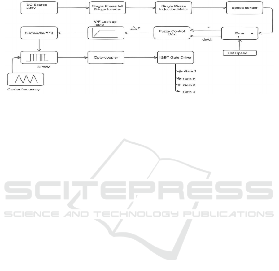
Figure 2.1: Block Diagram.
2.3 Simulation of MATLAB Fuzzy
Logic Controllers
MATLAB is a very good tool for implementation of
fuzzy logic controller design. MATLAB Fuzzy Logic
Toolbox allows a direct way of creating the FIS with
predefined membership functions and rule base. Also,
upon there are ways to convert the FIS file into the
Arduino IDE compatible .ino file using online
converters. For SPIM-based speed control, FIS can
be defined using Mamdani or Sugeno methodologies,
while inputs are defined by examples similar to error
in speed affecting output signals like voltage. A rule
base is generated from expert knowledge in the form
of if-then rules for computing the outputs of the
controller.
2.4 Role of IGBTs in Motor Drives
IGBTs play a very important role in motor drives. Its
high switching time, high efficiency, and high power-
handling capabilities improve the use with low losses
during switching. Since the losses associated with
SPIMs' switching are greatly reduced, more detail can
be taken into the control of motor speed and torque.
In addition, the implementation of a fuzzy logic
controller with IGBTs improves efficiency and quick
response.
2.5 Optocoupler
An optocoupler isolates the control circuitry from the
high-power section and utilizes light to transmit
signals. It ensures safe and noiseless communication
between sinusoidal pulse width modulation generator
and gate driver.
2.6 Gate Driver
The gate driver boosts the low-power control signals
from the optocoupler to effectively drive the gates of
the IGBTs. It supplies the necessary power and timing
to switch the IGBTs in the inverter, ensuring proper
control of the motor. In practical implementation
either TLP250 or IR21101 can be used for the
building the gate driving circuit, TLP250 is an
optocoupler with high frequency operating
characteristics that can be controlled by a
microcontroller , or the IR21101 can also be used as
Mosfet/IGBT gate driver.
3 METHODOLOGY
Our speed control system is based on
v/f(voltage/frequency) control of the single-phase
induction motor. In v/f control, the applied voltage to
the motor is varied in proportion to the frequency of
the ac supply to maintain a constant flux in the motor.
This approach ensures that the motor operates
efficiently across different speeds. Since the system
assumes a constant load torque, the torque demand
remains steady, and the control focuses on
maintaining the appropriate balance between voltage
and frequency to achieve the target speed.
3.1 Fuzzy Logic Controller
Fuzzy logic control (FLC) provides a practical
method for managing the speed of induction motors,
particularly in situations characterized by nonlinear
dynamics, varying loads, and uncertain conditions.
In contrast to traditional control techniques that
depend on exact mathematical models, FLC mimics
ISPES 2024 - International Conference on Intelligent and Sustainable Power and Energy Systems
180

human decision-making through linguistic rules,
allowing it to effectively manage the intricate
behaviour of motors. The process starts by gathering
inputs like the speed error (the difference between the
desired speed and the act. The linguistic variables are
explained as follows: “NL” is “Negative and Large”,
“NM” is “Negative and Medium”, “NS” is “Negative
and Small”, “ZZ” is “Zero”, “PS” is “Positive and
Small”, “PM” is “Positive and Medium” and “PL” is
“Positive and Large”. The membership range is
normalized to [-1, 1] by dividing the error of speed
before giving it to for the fuzzification, as illustrated
in Fig. 3.1.1.Fuzzy rules can be processed based on
knowledge about the control process, which is dealt
with linguistically in an "if-then" form. It eliminates
detailed knowledge of the mathematical model that
represents the control plant. Whose first three fuzzy
rules are represented as follows: If (speed error is
NL), and (speed error variation is NL), Then
(frequency change is NL) If (speed error is NM) and
(speed error variation is NL) Then (frequency
variation is NL) If (speed error is PM) and (speed
error variation is NL) Then (frequency variation is
NS) as shown in table 3.1.1
Figure 3.1.1 Fuzzy membership function.
Table 1: Membership Table.
e/de/dt NL NM NS ZE PL PM PS
NL NL NL NL NL ZE PS NM
NM NL NL NL NM PS ZE NS
NS NL NL NM NS PM PS ZE
ZE NL NM NS ZE PL PM PS
PL ZE PS PM PL PL PL PL
PM NS ZE PS PM PL PL PL
PS NM NS ZE PS PL PL PM
The surface plot's shape illustrates the fuzzy rules
used in the controller, demonstrating its response to
various combinations of error and change in error.
When both error and change in error are significant,
the controller enacts a stronger corrective action,
which is depicted by the peaks or dips in the plot. As
these values get closer to zero (the centre of the plot),
the output also approaches zero, signifying that the
system is nearing the desired state. The smooth
gradient across the surface showcases the fuzzy
controller's gradual response, preventing sudden
changes and ensuring a more fluid control action.
This visualization is helpful for fine-tuning the fuzzy
rules, enabling adjustments for either more aggressive
or more gradual responses to error, based on the
specific needs of the application.
Figure 3.1.2 Fuzzy logic surface plot.
3.2 Working
The 4 IGBTs in our circuit serve as the switches in a
full-bridge inverter, converting the DC input voltage
(230V) into single-phase AC voltage. This AC
voltage, with a frequency controlled by the PWM
signals, drives the motor at the desired speed based
on the V/f control strategy. In our circuit, the control
system is designed to compare the actual speed of the
motor with are reference speed. The reference speed
is the desired output speed that the motor should be
driven to. In the first diagram Fig.3.2.1, we notice the
control section of the system. The process of
controlling begins with an input reference signal
indicating the desired speed of the motor. This signal
is compared with the actual speed of the motor to
produce an error signal, which indicates a difference
in desired and the actual speeds. The error is
downscaled for easier processing, probably to get it
Adaptive Fuzzy Logic Control for Optimal Speed Regulation in Single Phase Induction Motors
181
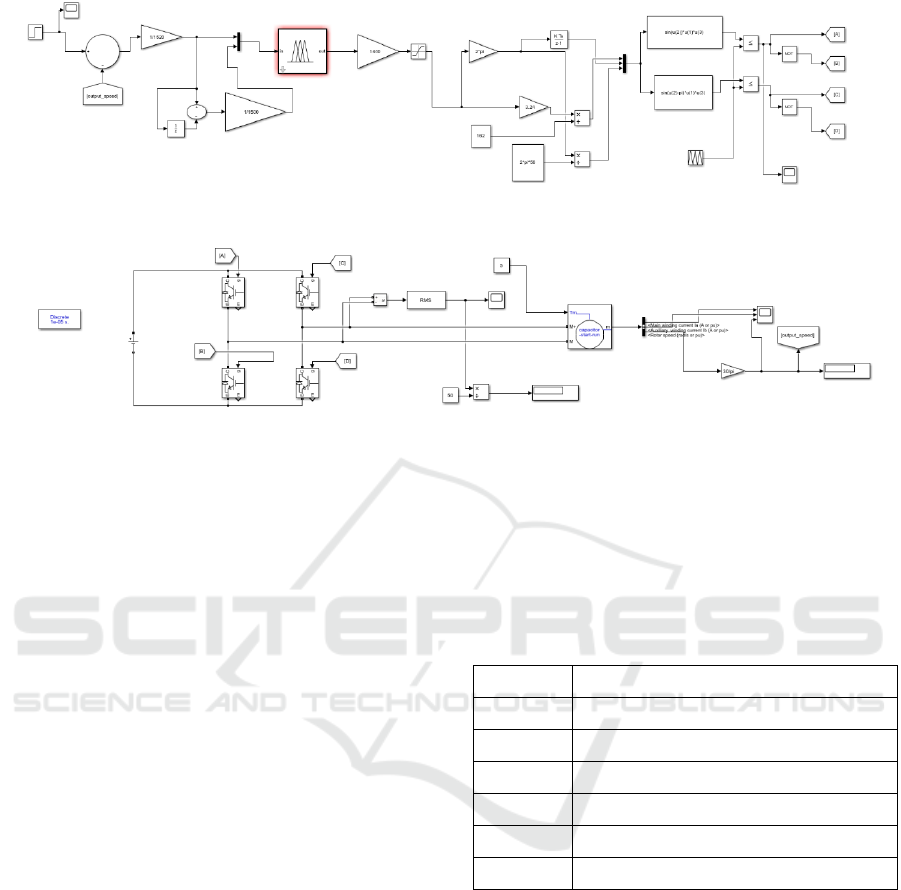
Figure 3.2.1: Fuzzy logic control circuit.
Figure 3.2.2: Motor driving circuit.
within the range expected by the fuzzy logic
controller. The fuzzy logic controller uses this error,
and possibly the rate of change in error, to determine
the necessary adjustments to the control signals.
These controller elements, in turn, dynamically adjust
the frequency and voltage parameters according to the
error to ensure that the V/F ratio achieves the desired
motor speed. Signal processing blocks and
trigonometric functions further refine the signals to
give single phase AC outputs that have been correctly
shifted to make them suitable for their role of driving
the motor.
The second diagram Figure 3.2.2, illustrates the
power circuit and motor model. A full bridge inverter,
made up of switches like IGBTs, receives the adjusted
frequency and voltage signals from the control
section and converts them into a single phase AC
output to power the motor. The inverter is managed
by signals labelled [A], [B], [C], and [D], which
correspond to the switching states required to create a
rotating magnetic field. This single phase output is
then applied to the induction motor model, which
simulates real motor behaviour with parameters such
as resistance, inductance, and back-EMF, providing a
realistic depiction of motor dynamics under varying
load conditions. The system features a feedback loop
where the motor’s actual speed and current are
measured and sent back to the controller. RMS blocks
assess the motor output characteristics, which can be
used for monitoring and control purposes.
Additionally, capacitors and filters are likely included
to stabilize and smooth the motor voltage, ensuring
that the AC supply to the motor remains steady. The
feedback loop enables continuous adjustments based
on realtime motor performance, and the output speed
is displayed as [output speed], confirming that the
motor is operating at the intended speed. Matlab tools
specification table: Most of the tools used are the
built-in functions/blocks. The tools used in the
Matlab are listed as following:
Table 2: Matlab tools used.
Sl No Tools
1 Fuzzy Control Toolbox
2 Saturation limit box
3 Discrete time integrator
4 Repeating sequence block
5 Relation operator block
6 Asynchronous Single Phase machine
3.2.1 SPWM Working
The repetitive sequence block here generates a
triangular waveform, given certain time and output
values. These time values are [0 1 2] * (1/10000),
which set the timing for the triangular carrier
waveform. Now, by multiplying these values
by1/10000, you create a time interval of
0.1milliseconds corresponding to a frequency of
10kHz. The output values are [-1 1 -1], which means
that the triangular waveform has oscillations between
-1 and 1, and it generates a repeating triangular shape.
Basically, the logical operator blocks help in
comparing the carrier waveform with the time
ISPES 2024 - International Conference on Intelligent and Sustainable Power and Energy Systems
182
varying sinusoidal signal generating the Sinusoidally
pulse width modulated signals for the gates of IGBT.
3.2.2 Logical Operator for SPWM
The sequence block here produces a triangular
waveform provided you have this set of time and
output values. These time values are [0 1 2]
*(1/10000), which determines the time on or off for
the triangular carrier waveform. By multiplying these
by 1/10000, you then get a time interval of
0.1milliseconds corresponding to a frequency of
10kHz. The output values are [-1 1 -1], which means
that the triangular waveform has the oscillations
between -1 and 1, and it generates a repeating
triangular shape.
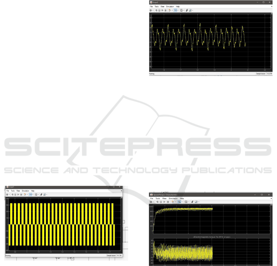
4 RESULT
The image shows the speed and electromagnetic
torque characteristics of a single-phase induction
motor controlled using a fuzzy controller. The graph
represents Fig 4.1, the output voltage for controlling
the speed of a single-phase induction motor using
pulse-width modulation (PWM). The horizontal axis
represents time, ranging from approximately 0.9 to
1.7 seconds. The vertical axis represents voltage, with
values ranging from -325 to 325 units. The consistent
voltage pulses demonstrate how varying the duty
cycle controls the power delivered to the motor,
ensuring precise speed regulation.
Figure 4.1: Output Voltage Graph
The graph displays Fig 4.2, the output current for the
speed control of a single-phase induction motor. The
x-axis represents time, ranging from approximately
1.6 to 2.2 seconds, while the y-axis represents current,
with values from -20 to 40 units. The waveform is
oscillatory, indicating fluctuating current over time.
These fluctuations correspond to the motor's response
to speed control inputs, essential for maintaining
desired speed and ensuring efficient operation. Even
though the output voltage waveform appears to be in
the form of square wave in the simulation, in practical
implementation it will appear as sinusoidal in shape
which can further be filtered for harmonics using
capacitors and inductors.
Figure 4.2: Output current graph.
The speed response Figure 4.3 of the single-phase
induction motor starts at zero and quickly increases
within the first second. Once it reaches about 900units
in RPM, the speed levels off with minor oscillations.
This pattern shows that the controller successfully
brings the motor to its target speed, though there are
slight variations in the steady state as the system
works to maintain that speed. The torque varies
around an average value, indicating dynamic
adjustments to keep the desired speed efficiently.
These variations are crucial for ensuring stable and
effective motor operation.
Figure 4.3: Output speed and Torque.
The most important thing to note in this configuration
of speed control is that we have not included any kind
of inner control loop for controlling the current which
is often times a good practice to ensure the safety of
the motor’s windings, however the single Fuzzy logic
controller is enough to implement both the outer
speed and inner current loop
Adaptive Fuzzy Logic Control for Optimal Speed Regulation in Single Phase Induction Motors
183

REFERENCES
Abdelwanis, M. I., Fayez F. M. El-Sousy, & Ali, M. M.
(2023). A Fuzzy-Based Proportional–Integral–
Derivative with Space-Vector Control and Direct
Thrust Control for a Linear Induction Motor.
Electronics, 12(24), 4955–4955.
https://doi.org/10.3390/electronics12244955
Alwadie, A. (2018). A Concise Review of Control
Techniques for Reliable and Efficient Control of
Induction Motor. International Journal of Power
Electronics and Drive Systems (IJPEDS), 9(3), 1124.
https://doi.org/10.11591/ijpeds.v9.i3.pp1124-1139
El Ouanjli, N., Derouich, A., El Ghzizal, A., Motahhir, S.,
Chebabhi, A., El Mourabit, Y., & Taoussi, M. (2019).
Modern improvement techniques of direct torque
control for induction motor drives - a review.
Protection and Control of Modern Power Systems, 4(1).
https://doi.org/10.1186/s41601-019-0125-5
Firdaus, A. Z. A. (2019). Design and Simulation of Fuzzy
Logic Controller for Variable Frequency Drive of Three
Phase AC Induction Motor. Journal of Advanced
Research in Dynamical and Control Systems, 11(12-
SPECIAL ISSUE), 834–842.
https://doi.org/10.5373/jardcs/v11sp12/20193283
Guiza, D., Djamel Ounnas, Youcef Soufi, & Naoual
Tidjani. (2023). Design and Real Hardware
Implementation of Fuzzy Logic Controller for DC-DC
Boost Converter. PRZEGLĄD
ELEKTROTECHNICZNY, 1(7).
https://doi.org/10.15199/48.2023.07.19
Hannan, M. A., Ali, J. A., Mohamed, A., & Hussain, A.
(2018). Optimization techniques to enhance the
performance of induction motor drives: A review.
Renewable and Sustainable Energy Reviews, 81, 1611–
1626. https://doi.org/10.1016/j.rser.2017.05.240
Hannan, M. A., Ali, J. A., Mohamed, A., & Hussain, A.
(2018). Optimization techniques to enhance the
performance of induction motor drives: A review.
Renewable and Sustainable Energy Reviews, 81, 1611–
1626. https://doi.org/10.1016/j.rser.2017.05.240
Maghfiroh, H., Saputro, J. S., Adriyanto, F., Sujono, A., &
Lambang, R. L. (2021). Performance Evaluation of
Fuzzy-PID in Speed Control of Three Phase Induction
Motor. IOP Conference Series: Materials Science and
Engineering, 1096(1), 012071.
https://doi.org/10.1088/1757-899x/1096/1/012071
Maghfiroh, H., Wahyunggoro, O., Cahyadi, A. I., Lian, K.
L., & Ke, B. R. (2016). Speed Control of a Single Taipei
Mass Rapid Transit System Train by Using a Single
Input Fuzzy Logic Controller. International Journal of
Electrical and Computer Engineering (IJECE), 6(2),
621. https://doi.org/10.11591/ijece.v6i2.8123
Overview of advanced control strategies for electric
machines. (2017). Chinese Journal of Electrical
Engineering, 3(2), 53–61.
https://doi.org/10.23919/cjee.2017.8048412
Plamena Dinolova, Vyara Ruseva, & Ognyan Dinolov.
(2023). Energy Efficiency of Induction Motor Drives:
State of the Art, Analysis and Recommendations.
Energies, 16(20), 7136–7136.
https://doi.org/10.3390/en16207136
Rekha Tidke, & Chowdhury, A. (2024). An experimental
analysis of fuzzy logic-sliding mode based IFOC
controlled induction motor drive. AIMS Electronics and
Electrical Engineering, 8(3), 340–359.
https://doi.org/10.3934/electreng.2024016
Sahoo, A. Ku., & Jena, R. Ku. (2022). Improved DTC
strategy with fuzzy logic controller for induction motor
driven electric vehicle. AIMS Electronics and Electrical
Engineering, 6(3), 296–316.
https://doi.org/10.3934/electreng.2022018
Shaikh, A. (2014). Speed Control of Induction Motor by
V/F Method Using Fuzzy Technique, IJSR, Call for
Papers, Online Journal. International Journal of
Science and Research (IJSR).
https://www.ijsr.net/getabstract.php?paperid=ART201
97800
Suwongsa, T., Areerak, K., Areerak, K., & Pakdeeto, J.
(2021). Energy Saving Approach for an Electric Pump
Using a Fuzzy Controller. Energies, 14(11), 3330.
https://doi.org/10.3390/en14113330
ISPES 2024 - International Conference on Intelligent and Sustainable Power and Energy Systems
184
