
MATLAB Based Graphical User Interface for Parameter
Computation of Type II and Type III Controllers for DC DC
Converters
Hariharan J
a
, J Harish Arjun
b
, Karthik M Rao
c
, Sohan P
d
and M. Premkumar
e
Department of Electrical and Electronics Engineering, Dayananda Sagar College of Engineering,
Kumaraswamy Layout, Bangalore, Karnataka, India
Keywords: DC-DC Converter, GUI, Type II and Type III Controller, MATLAB.
Abstract: A MATLAB-based graphical user interface (GUI) is presented for the optimal design of Type II and Type III
controllers for DC-DC converters, including buck, boost, and buck-boost types. This GUI combines
traditional design methods with computational algorithms, allowing users to automatically calculate and
display the required parameter values for both controller types. It simplifies the design process while, at the
same time making sure that the
converters
operate
with enhanced
stability,
faster
transient
response,
and
reduced
steady-state error. This interface thereby supports optimization under various conditions of
operation, thus facilitating the gap between theoretical analyses and practical implementation, making it
easier for engineers to achieve optimal.
1 INTRODUCTION
This study focuses on the development of an
advanced and user-friendly boundary breaker for both
Type II and Type III controllers in DC -In DC
converters. These converters are essential
components of power management systems in all
modern electronics and require precision to ensure
robustness and efficiency. The design boundary grid
implemented in MATLAB is mainly designed to
allow the calculation of compensator parameters,
thereby simplifying, and simplifying the design
process for engineers and researchers. This paper
aims to improve the stability and performance of DC-
DC converters on different topologies, including
buck, boost and buck-boost configurations. The core
of this paper is to determine a MATLAB-based
design boundary that lets users input specific
parameters for the DC-DC converters.
a
https://orcid.org/0009-0002-3177-794X
b
https://orcid.org/0009-0007-8220-083X
c
https://orcid.org/0009-0005-6113-9449
d
https://orcid.org/0009-0004-9428-432X
e
https://orcid.org/0000-0003-1032-4634
Once this information is obtained, the bounding
unit determines compensator parameter values with
traditional methods and computation algorithms both
for Type II and Type III compensators. This
automated process not only speeds up the design
process but reduces the risk of errors, something
which ensures timely and careful planning. The heat
socket further improves the design by generating
various frequency curves for the DC-DC converter,
providing visual insight into the frequency response
of the system and aiding in the analysis of stability
and yield. The primary goal of this paper is to analyze
and optimize stability for DC-DC converters using
type II and type III controllers. By analyzing the
performance of these two types, the paper intends to
identify the optimal conditions under which each
controller and converter makes itself manifest.
The ability to easily switch between Type II and
Type III controllers within the interface gives the
engineers enough flexibility to address various
150
J, H., Harish Arjun, J., M Rao, K., P, S. and Premkumar, M.
MATLAB Based Graphical User Interface for Parameter Computation of Type II and Type III Controllers for DC DC Converters.
DOI: 10.5220/0013652400004639
In Proceedings of the 2nd International Conference on Intelligent and Sustainable Power and Energy Systems (ISPES 2024), pages 150-156
ISBN: 978-989-758-756-6
Copyright © 2025 by Paper published under CC license (CC BY-NC-ND 4.0)

operational scenarios and performance demands.
Adaptability is actually very important because
different topologies of DC-DC converters and load
conditions necessarily require different control
strategies to acquire optimal performance. In this
regard, the interface allows for a more tailored
approach to design with the incorporation of both
types of controllers; hence, each converter achieves
the highest level of stability and efficiency regardless
of the specifics of the application or environment. The
paper further explores how these controllers impact
the transient and steady-state error of DC-DC
converters. Using careful tuning of compensator
parameters, the interface minimizes such critical
metrics for the performance results in faster response
times and stable operations.
2 LITERATURE REVIEW
The vast literature provides various strategies to
control and optimize DC-DC converters, which
continue to advance in this field. There is one
innovation introduced through a tri- state buck-boost
converter with an optimized Type-3 controller using
Particle Swarm Optimization (PSO), which
effectively removes the RHP zero of conventional
buck- boost converters, providing greatly improved
control-to-output stability and dynamic parameters
and open-loop gain visualization for various
topologies like buck, boost, or buck-boost converters.
The result is a streamlined design for controllers that
ensures better transient and steady-state responses. In
addition, the robustness and flexibility of PID
controllers on DC-DC converters are highlighted. On
voltage-mode buck converters, digital PID controllers
have shown much higher phase margins and better
stability and overall performance with such digital
control elements as ADCs and digital PWM
Another detailed investigation regarding Type-II
and Type- III controllers is that the controllers have
transient responses and also achieve a good steady
state in high-order converters, such as fourth-order
systems. Models like these were tested for the
practical case with the help of MATLAB-Simulink
simulations. The studies on the application of
classical PID controllers to boost converters
emphasize the ability to maintain voltage regulation,
even in the presence of variations due to input and
load conditions, with some minimizing harmonic
distortion, improving power factors, and maximizing
efficiency. However, Type-II controllers provide
easier implementations and satisfactory performance
for certain applications, so there is still scope to carry
out a comparison. Algorithmic developments,
incorporating PSO and hybrid techniques, have been
routinely applied to fine-tune the controller
parameters for best performance, tackling challenges
such as reduced settling time and better dynamic
response. Relative studies also express the need for
controller selection to enhance the reliability of power
conversion systems used in critical applications, such
as renewable energy, power grids, and
telecommunications. This also proved that practical
challenges in achieving consistent control of DC-DC
converters under varying load currents and input
voltage conditions are acknowledged by the research,
especially in industrial applications. Despite these
advances, the integration of generalized interfaces,
unified frameworks, and broader topological
applicability remains limited, indicating a fragmented
research landscape that calls for consolidation.
Reviewing the presented studies reveals
significant results but also some significant gaps.
Present work has been much focused on Type-III
controllers and their application on the different types
of converters while the focus on Type-II controllers
is less. This creates a comparative gap in
understanding applications that could be linked with
this. Most works concentrate on specific converters,
for instance, on a buck or boost and do not present
generalized design interfaces that may accommodate
a broader range of converters, like buck-boost. While
techniques such as PSO and advanced algorithms are
applied for controller tuning in the techniques used
are highly scenario-specific and cannot be
generalized to multiple controllers or different
topologies optimization techniques, and comparative
evaluations of diverse controller types.
3 METHODOLOGY
The methodology in this paper is understood to be an
organized and detailed approach towards the
designing of a Graphical User Interface (GUI) aimed
at the optimization of the design and analysis of the
Type II and Type III controllers for DC-DC
converters. The first stage consisted of meticulous
literature reviews and theoretical analysis to lay down
the understanding from a fundamental point of
control strategies for DC-DC converters, primarily
Type II and Type III compensators. This stage
incorporates a detailed study of mathematical
modelling and transfer functions relevant to various
types of converters, such as buck, boost, and buck-
boost. Ideally, the goal is to create a fundamental
basis for the subsequent stages. Following the
MATLAB Based Graphical User Interface for Parameter Computation of Type II and Type III Controllers for DC DC Converters
151

theoretical foundations, system modelling and
simulation is the next step, where the selected DC-DC
converters are modelled using MATLAB/Simulink.
In the discussion that follows, building small-signal
models and derivation of transfer functions for each
converter type permits an accurate simulation of the
converters' open-loop behavior, thus gaining insight
into their inherent system dynamics. In the controller
design and parameter selection phase, Type II and
Type III compensators are designed based on the
previously derived transfer functions. This involves
employing Bode plot analysis to fine-tune the
compensator parameters—such as gain, poles, and
zeros—to achieve the desired stability and
performance criteria. The goal of this step is to ensure
an adequate transient response and steady-state
performance, enhancing the controller's overall
efficiency and robustness.
3.1 K-Factor Method
K Factor was created primarily to assist in the
determination of amplifier R and C values. This is
defined as the root of the ratio of the pole to the
zero frequency in Type 2 controllers and the ratio
of double pole frequency over double zero
in Type 3 amplifiers. Choose a cross-over frequency,
desired phase margin, determine the required
amplifier gain and calculate the
required phase boost. Calculate the Phase boost using
Eq. 1 (Prokopev et al., 2019).
𝐵𝑜𝑜𝑠𝑡 = 𝑀 − 𝑃 – 90 (1)
Where, M = desired phase margin (degrees) and p =
modulator phase shift (degrees). The mentioned
expressions apply to Type 2 amplifiers only.
𝐾 = 𝑇𝑎𝑛 [(
) + 45]
(2)
converters and not applicable to a wide range of
variations in input-output conditions for scalable
solutions or interfaces. Overall, the research is
fragmented, and there is a need for a unified
framework that integrates generalized interfaces,
𝐶
=
(3)
𝐶
=𝐶
(𝐾
−1) (4)
𝑅
=
(5)
𝐾=𝑇
𝑩𝒐𝒐𝒔𝒕
+ 452 (6)
𝐶
=
(7)
𝐶
=𝐶
(𝐾 − 1) (8)
𝑅
=
√
(9)
𝑅
=
(10)
𝐶
=
(11)
These parametric equations allow the precise
calculation and error analysis of loop performance
without the iterative process normally associated
with stability analysis.
3.2 PSO Algorithm
Particle Swarm Optimization (PSO) is an
evolutionary algorithm that optimizes the continuous
or discrete, linear or nonlinear, constrained or
unconstrained, and non- differentiable functions by
trying iteratively to improve the solutions with
respect to different parameter values (Chan et al.,
2015). The key components of PSO include:
Particles: These are individual candidate solutions
represented as vectors in a multidimensional space,
where each vector corresponds to a set of parameters
(in this case, compensator values R and C).
Position and Velocity: Each particle has a position in
the search space and a velocity that determines how
it moves within that space. The position of the
particle represents a potential solution (e.g., a set of
values for R and C), while the velocity determines
how the particle updates its position in subsequent
iterations.
Best Positions:
Personal best (pBest): Each particle tracks its best
solution found so far in terms of the objective
function.
Global best (gBest): The best solution found by any
particle in the entire swarm.
Update Rules: The position and velocity of each
particle are updated according to the following
equations:
𝑉
()
=𝑊.𝑉
()
+𝐶
𝑟
𝑃
−𝑥
(
)
+
𝐶
𝑟
𝑔
−𝑥
(
)
(12)
𝑥
()
=𝑥
()
+𝑉
()
(13)
Where: v
(k)
is the velocity of particle i at iteration k,
x
(k)
is the position of particle i at iteration k, w is the
inertia weight controlling the influence of the
previous velocity, c1 and c2 are acceleration
coefficients that control the attraction to personal and
ISPES 2024 - International Conference on Intelligent and Sustainable Power and Energy Systems
152
global best positions, r1 and r2 are random numbers
between 0 and 1, pBest and gBest are the personal and
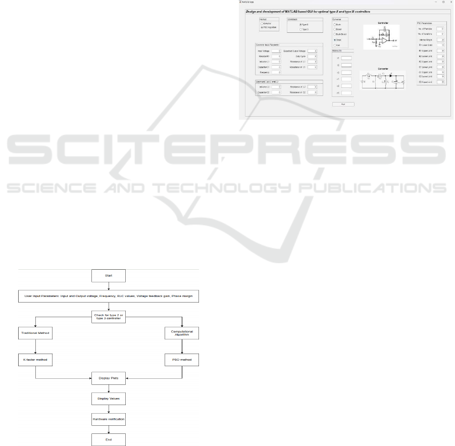
global best positions, respectively. The flowchart of
the PSO algorithm is shown in Fig. 1.
Particle Swarm Optimization is one viable
optimization technique to use in fine-tuning the
parameters of control compensators, such as
resistance and capacitance, to optimize system
performance. Because such behavior of particles
finds optimal/near-optimal solutions in the parameter
space within reasonable computational time, it is,
therefore, efficient in search. This places PSO as a
valuable tool in compensator design to optimize
system performance in any application. Then comes
the simulation stage of the paper, wherein the closed-
loop system would be simulated with all the designed
compensators put in place. At this stage, the
performance based on stability, transient response,
and steady-state error is evaluated with iteration of
the tuning of compensator parameters for better
performance. Through this iteration, there is a
refining of the compensator design to meet desired
specifications in real applications. Finally, a
frequency response analysis and visualization are
carried out to understand and interpret the system's
frequency response characteristics. With tools like
Bode plots, the paper visually examines the effects of
variations in parameters on system stability and
performance. This stage helps us understand the
trade-offs available for controller design and how
decisions are made, and modifications are done to
achieve an optimal balance in competing
performance metrics. This approach attempts to
achieve a robust, user-friendly GUI by efficiently
guiding users through the intricate process of
designing and analyzing Type-II and Type-III
controllers for DC- DC converters.
Figure 3.1: Flowchart
4 RESULTS AND DISCUSSIONS
The proposed method successfully integrates a
MATLAB-based GUI for the design and analysis of
Type II and Type III controllers for DC-DC
converters, as shown in Fig. 2. The GUI is user-
friendly and incorporates robust computational
algorithms to automate the calculation of
compensator parameters such as resistors and
capacitors. These parameters are directly derived
from the transfer functions of various converter
topologies, such as buck, boost, and buck-boost, and
have been seamlessly integrated into MATLAB
Simulink simulations.
Figure 4.1: GUI
Simulation of the closed-loop behavior of DC-DC
converters by the designed compensators provided a
good validation of the system performance. The
interface between the GUI and Simulink provides
real-time visualization and analysis of the system
dynamics, frequency response, and stability margins.
Such analysis tools as Bode plots are very useful in
giving some insight into gain and phase margins and
aid in the fine-tuning of the
parameters of the
compensators to optimal performance. Key results
achieved include:
Automated Parameter Integration: The GUI
successfully calculated and transferred compensator
parameters to MATLAB Simulink, streamlining the
design and simulation process.
Improved Converter Stability: The controllers
designed via the GUI enhanced the stability of the
converters, maintaining steady operation across
varying load and input conditions.
Enhanced Transient Response: Simulations
demonstrated faster response times and reduced
overshoot, ensuring the converters' ability to handle
sudden changes in input or load.
Accurate Frequency Response Visualization: Bode
plots generated through the GUI provided clear
insights into stability metrics and trade-offs, aiding in
MATLAB Based Graphical User Interface for Parameter Computation of Type II and Type III Controllers for DC DC Converters
153
iterative tuning.
Wide Applicability: The GUI's versatility in
supporting multiple converter topologies validates its
effectiveness as a universal tool for power electronics
engineers.
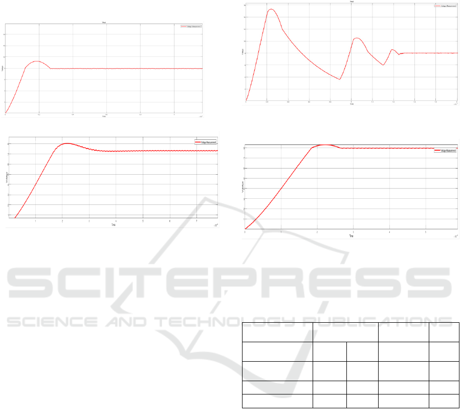
(a)
(b)
Figure 4.2.1: Output Waveform for Type -2 controller for
Buck Converter; (a) K-factor, (b) PSO
From the values obtained from the GUI, it is observed
that the maximum overshoot is the same for both the
K-factor and PSO methods, but rise time is less in the
PSO method than the K-Factor method and settling
time is less in the K- Factor method than the PSO
method, so it is concluded that and K-Factor and PSO
method is both suitable for getting the required output
for Type-III controller for the buck converter. The
output voltage obtained for the buck converter with
the K-factor method and PSO method is presented in
Fig. 4. The time domain specifications of the buck
converter with Type-II and Type-III controllers are
recorded in Table I.
4.1 Type II and Type III Controller
Analysis for Buck Converter
From the values obtained from the GUI, it is observed
that the maximum overshoot, rise time and settling
time is less in the PSO method than in the K-Factor
method, so it is obvious that the PSO method is more
suitable for getting the required output for Type-II
controller for the buck converter. The output voltage
obtained for the buck converter with the K-factor
method and PSO method is presented in Fig. 3. The
time domain specifications of the buck converter with
Type-II and Type-III controllers are recorded in Table
I.
(a)
(b)
Figure 4.2.2: Output Waveform for Type -3controller for
Buck Converter; (a) K-factor, (b) PSO
Table 1: Time Domain Specifications values for Buck
converter with controllers
Buck (Type-II) Buck (Type-
III)
Specifications K-
Factor
PSO K-Factor PSO
Maximum
Overshoot
15.0% 14.6% 87.5% 87.5%
Rise Time (s) 0.00118 0.00117 0.00118 0.00117
Settling Time (s) 0.00265 0.00261 0.00146 0.00196
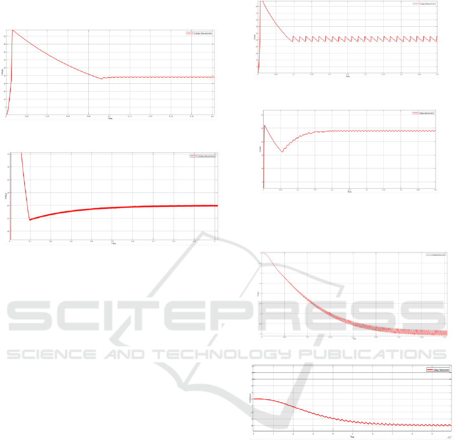
4.2 Type II and Type III Controller
Analysis for Boostconverter
From the values obtained from the GUI, it is observed
that the maximum overshoot is less in the K-Factor
method than the PSO method, but rise time is less in
the K-Factor method than the PSO method and
settling time is less in the PSO method than the K-
Factor method, so it is concluded that K-Factor
method is more suitable for getting the required
output for Type-II controller for boost converter.
The output voltage obtained for the buck converter
with the K-factor method and PSO method is
presented in Fig. 5. The time domain specifications of
ISPES 2024 - International Conference on Intelligent and Sustainable Power and Energy Systems
154
the boost converter with Type-II and Type-III
controllers are recorded in Table II.
(a)
(b)
Figure 4.2.3: Output Waveform for Type-II controller for
Boost Converter; (a) K-factor, (b) PSO
From the values obtained from the GUI, it is observed
that the maximum overshoot is less in the K-Factor
method than the PSO method, but the rise time is the
same in the K- Factor method and the PSO method
and settling time is less in the K-Factor method than
the PSO method, so it sic concluded that K-Factor
method is more suitable for getting the required output
for Type-II controller for boost converter. The output
voltage obtained for the buck converter with the K-
factor method and PSO method is presented in Fig. 6.
The time domain specifications of the boost converter
with Type-II and Type-III controllers are recorded in
Table II.
(a)
(b)
Figure 4.2.4: Output Waveform for Type-III controller for
Boost Converter; (a) K-factor, (b) PSO
(a)
(b)
Figure 4.2.5: Output Waveform for Type-II controller for
Buck- Boost Converter; (a) K-factor, (b) PSO
From the values obtained from the GUI, it is
observed that the maximum overshoot, rise time and
settling time are less in the K-Factor method than in
the PSO method, so it is concluded that K-Factor is
more suitable for getting the required output for
Type-III controller for the buck-boost converter. The
output voltage obtained for the buck converter with
the K-factor method and PSO method is presented in
Fig. 8. The time domain specifications of the buck-
boost converter with Type-II and Type-III controllers
are recorded in Table III
MATLAB Based Graphical User Interface for Parameter Computation of Type II and Type III Controllers for DC DC Converters
155
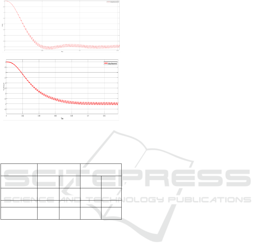
(a)
(b)
Figure 4.2.6: Output Waveform for Type-III controller for
Buck-Boost Converter; (a) K-factor, (b) PSO
Table 3: Time Domain Specifications for Buck-Boost
converter with controllers
Buc
k
-Boost
(T
ype
-II)
Buc
k
-Boost
(T
ype
-III)
Specifications
K
-
Factor
PSO
K
-
Factor
PSO
Maximum
Overshoot
7.5% 5.0% 5.0% 12.5%
Rise Time (s) 0.03000 0.01640 0.00460 0.01760
Settlin
g
Time
(s)
0.04020 0.02482 0.01842 0.02220
5 CONCLUSIONS
By presenting MATLAB-based GUI, the design of
Type II and Type III controllers for DC-DC
converters can easily be performed, in the sense that
engineers can obtain optimized converter
performance in terms of improved stability, faster
transient response and lower steady-state error. The
interface integrates computational algorithms with
traditional design techniques to increase precision
and efficiency in parameter selection for a wide range
of converter types such as buck, boost, and buck-
boost. The dual controller characteristic of GUI
enables greater performance over a broad range of
operating conditions between theoretical models and
practical realization.
The GUI can be extended for a future scope with
other converter types, such as Cuk or SEPIC
converters and other control strategies such as
predictive or adaptive control. Its utility could further
be expanded with integration to real- time hardware
in the loop testing and machine learning algorithms
for automated optimization. In addition, the web-
based interface would increase accessibility and
usability to the broader engineering audience.
REFERENCES
Andrey Prokopev, Zhasurbek Nabizhanov, Vladimir
Ivanchura, & Rurik Emelyanov. (2019). Design of
Controllers for Higher Order Systems. 2019
International Multi-Conference on Engineering,
Computer and Information Sciences (SIBIRCON),
0607–0611.
https://doi.org/10.1109/sibircon48586.2019.8958442
Chan, N. K.-F., Lam, N. C.-S., Zeng, N. W.-L., Zheng, N.
W.-M., Sin, N. S.-W., & Wong, N.
M.-C. (2015). Generalized Type III controller design
interface for DC-DC converters. 1–6.
https://doi.org/10.1109/tencon.2015.7373052
De, K., Mohanty, S., & Prasad, M. (2019). Modelling,
Design and Control of a Step-Up Chopper Using PID
Controller. International Journal of Research and
Innovation in Applied Science (IJRIAS) |, IV, 2454–
6194.
https://www.rsisinternational.org/journals/ijrias/Digita
lLibr ary/Vol.4&Issue1/18-23.pdf
Mirza Fuad Adnan, Mohammad Abdul Moin Oninda,
Mirza Muntasir Nishat, & Nafiul Islam. (2017). Design
and Simulation of a DC - DC Boost Converter with PID
Controller for Enhanced Performance. International
Journal of Engineering Research And, V6(09).
https://doi.org/10.17577/ijertv6is090029
Muhammad Khamim Asy'ari, & Musyafa, A. (2018).
Design of Buck Converter Based on Interval Type-2
Fuzzy Logic Controller. 5, 153–156.
https://doi.org/10.1109/isitia.2018.8711236
Rana, N., Ghosh, A., & Banerjee, S. (2018). Development
of an Improved Tristate Buck–Boost Converter With
Optimized Type-3 Controller. IEEE Journal of
Emerging and Selected Topics in Power Electronics,
6(1), 400–415.
https://doi.org/10.1109/jestpe.2017.2724847
S Saurav, & Ghosh, A. (2021). Design and Analysis of PID,
Type II and Type III controllers for Fourth Order Boost
Converter. 323–328.
https://doi.org/10.1109/icees51510.2021.9383687
Tiwari, N., & Tiwari, A. N. (2018). Performance Analysis
of Unidirectional and Bidirectional Buck-Boost
Converter Using PID Controller. 1–6.
https://doi.org/10.1109/iementech.2018.8465229
Wang, C.-Y., Ou, Y.-C., Wu, C.-F., & Muh-Tian Shiue.
(2015). A voltage-mode DC-DC buck converter with
digital PID controller. 2322–2326.
https://doi.org/10.1109/fskd.2015.7382315
ISPES 2024 - International Conference on Intelligent and Sustainable Power and Energy Systems
156
