
Multilevel Voltage Source Converter for HVDC Transmission System
Selvamaari I
a
, Sandeep Kumar S
b
, Sakthi Saravanan N
c
and Selvanayagam M
d
S A Engineering College, Anna University, Avadi-Poonamallee Road, Tamil Nadu, India
Keywords: High Voltage Direct Current (HVDC) Transmission, Multilevel Voltage Source Converter (VSC), Power
Quality Management, Uninterruptible Power Quality Conditioner (UPQC), System Cost Reduction in HVDC.
Abstract: This paper introduces a novel multilevel Voltage Source Converter (VSC) for High Voltage Direct Current
(HVDC) systems, featuring an integrated Uninterruptible Power Quality Conditioner (UPQC) to improve
power quality and performance. Unlike traditional Modular Multilevel Converters (MMC), which are
complex and costly, the proposed VSC uses series full-bridge submodules and an AC side unfolder to
minimize component requirements and reduce switching losses. The advanced control strategy regulates
active/reactive power and maintains capacitor voltage balance, enhancing stability and efficiency. Simulations
confirm this design's superior performance, highlighting its potential as an efficient, resilient solution for
modern HVDC applications.
1 INTRODUCTION
High Voltage Direct Current (HVDC) systems are
essential for modern energy infrastructure due to their
efficiency in transmitting large power loads over long
distances. This efficiency makes HVDC technology
highly suitable for integrating renewable energy
sources, such as wind and solar, into power grids,
thereby supporting sustainable energy solutions. By
minimizing transmission losses and stabilizing grids,
HVDC plays a crucial role in enhancing the reliability
and reach of energy networks. A common HVDC
technology is the Modular Multilevel Converter
(MMC), which offers scalability and flexibility in
power transmission. MMCs use numerous
submodules to manage high voltage levels, making
them suitable for scaling with power demands.
However, the high component count in MMC
systems leads to increased costs and complex control
requirements. Balancing voltage across submodules
is particularly challenging under variable loads, while
the large number of components contributes to
switching losses, affecting system efficiency and
reliability. These factors add to the operational
complexity and costs of MMC-based HVDC systems.
a
https://orcid.org/0009-0003-1152-9006
b
https://orcid.org/0000-0003-3164-0572
c
https://orcid.org/0009-0003-5466-6019
d
https://orcid.org/0009-0003-9949-8418
The proposed solution introduces a novel
multilevel Voltage Source Converter (VSC) that
integrates full-bridge submodules and an AC side
unfolder, significantly reducing component count
compared to traditional MMC designs. This reduced
component structure simplifies the control system,
lowering costs and enhancing efficiency.
Additionally, by operating most switches in a soft-
switching mode, the design minimizes switching
losses and thermal stress, which improves the
converter’s reliability and longevity. This streamlined
design supports an HVDC system that is both cost-
effective and more efficient than conventional MMC
approaches.
The proposed VSC incorporates an
Uninterruptible Power Quality Conditioner (UPQC),
which enables effective management of power
quality disturbances such as voltage sags, swells, and
harmonics. This feature ensures a stable, high-quality
power supply, an increasingly important aspect of
modern grids. An advanced control strategy further
optimizes the VSC by balancing active and reactive
power, maintaining capacitor voltage, and adjusting
to dynamic load conditions. This approach offers a
I, S., Kumar S, S., Saravanan N, S. and M, S.
Multilevel Voltage Source Converter for HVDC Transmission System.
DOI: 10.5220/0013652100004639
In Proceedings of the 2nd International Conference on Intelligent and Sustainable Power and Energy Systems (ISPES 2024), pages 135-139
ISBN: 978-989-758-756-6
Copyright © 2025 by Paper published under CC license (CC BY-NC-ND 4.0)
135

sustainable and resilient HVDC solution, crucial as
renewable energy sources continue to expand within
global power networks.
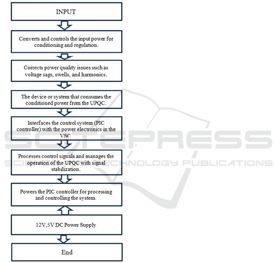
2 COMPONENTS
A Unified Power Quality Conditioner (UPQC)
system. Input power is processed through a Voltage
Source Converter (VSC) and regulated by the UPQC
to improve power quality for the load. A PIC
controller with a buffer manages the control signals,
supported by a 5V DC power supply.
A driver circuit, powered by 12V DC, interfaces
the controller with the VSC. The system ensures
reliable and clean power delivery to the load.
2.1 Voltage Source Converter (VSC)
The Voltage Source Converter (VSC) utilizes a
topology of series full-bridge submodules, which
enhances efficiency while reducing the number of
components compared to Modular Multilevel
Converters (MMC). It employs power semiconductor
switches, such as IGBTs or MOSFETs, arranged in
full-bridge configurations to facilitate soft-switching,
thereby minimizing switching losses. The VSC is
designed to achieve a DC-link voltage 3.33 times
greater than the AC-side RMS voltage, ensuring
balanced stress across both the converter and
transformer components.
2.2 Uninterruptible Power Quality
Conditioner (UPQC)
Uninterruptible Power Quality Conditioner (UPQC)
integrates with the VSC to effectively mitigate power
quality disturbances, improving voltage regulation
and reactive power supply as needed. This system
includes both series and shunt converters, along with
voltage and current sensors and control circuitry,
which work together to ensure smooth operation
under varying load conditions, thereby enhancing
overall system performance and reliability.
2.3 Load
The load in the system can be either resistive or
inductive, representing the actual load conditions in
simulations. For this setup, it is specified at 12V DC,
simulating typical operational conditions that the
VSC and UPQC are designed to handle. This load
configuration is essential for evaluating the
performance and effectiveness of the overall system
under realistic scenarios.
2.4 Driver Circuit
The driver circuit's primary purpose is to convert
control signals from the PIC controller into gate drive
signals that activate the VSC switches. Operating on
a 5V DC supply, the driver circuit ensures
compatibility with the outputs of the microcontroller.
This circuit plays a crucial role in facilitating reliable
switching operations of the VSC, thereby maintaining
the overall efficiency and effectiveness of the system.
2.5 PIC Controller with Buffer
The PIC controller serves as the main control unit for
the system, executing an advanced control strategy to
regulate both active and reactive power. To enhance
stability and reliability, a buffer circuit isolates the
PIC controller from the high-power switching
elements of the VSC.
This isolation ensures that the controller can
effectively manage system operations without being
adversely affected by high voltage or current
fluctuations during switching events.
3 SIMULATION PROCEDURE
A The simulation showcases a high-voltage direct
current (HVDC) transmission system designed for
efficient long-distance power transfer. It connects two
230 kV, 50 Hz, 2000 MVA AC systems.
Station 1 (Rectifier): Converts AC to DC for
transmission using a Voltage Source Converter
(VSC).
HVDC Cable: A 75 km cable transmits DC power
with reduced losses.
Station 2 (Inverter): Converts the DC back to AC
for integration into the second AC system.
Both stations incorporate VSC pole control for
precise operation and data acquisition systems for
signal recording and system monitoring. A simulated
three-phase fault near Station 2 evaluates the system's
stability, fault tolerance, and response under
disturbance. This system highlights efficient power
transfer and robust fault management.
A high-voltage direct current (HVDC)
transmission system, an advanced and highly efficient
technology for long-distance power transmission.
HVDC systems are widely used to transfer bulk
power over long distances with minimal losses,
making them a preferred choice for interconnecting
ISPES 2024 - International Conference on Intelligent and Sustainable Power and Energy Systems
136

distant AC grids or for projects that involve
submarine or underground cables. The simulation
focuses on the key operational aspects, fault-handling
capabilities, and the stability of an HVDC system.
This system connects two large AC grids, each
operating at 230 kV, 50 Hz, and with a power rating
of 2000 MVA. The first AC grid supplies power to
Station 1, which functions as a rectifier, converting
the AC power into direct current (DC) for
transmission. The rectification process is controlled
using Voltage Source Converter (VSC) technology,
which allows precise regulation of the DC voltage
and current, ensuring smooth power transfer. VSC
technology also enables fast response to changes in
load or grid conditions, making the system more
stable and adaptive to fluctuations.
Once converted to DC, the power is transmitted
over a 75 km HVDC cable. The use of DC for long-
distance transmission offers several advantages over
AC systems, including reduced energy losses and the
elimination of reactive power issues. HVDC cables
are also more efficient for submarine and
underground installations, as they require fewer
conductors and have a lower footprint. This feature
makes HVDC systems particularly suitable for
applications such as cross-border power exchanges or
linking offshore wind farms to the main grid.
At the receiving end, Station 2 acts as an inverter,
converting the DC power back into AC for integration
into the second AC grid. Like the rectifier, the
inverter station also uses VSC technology to ensure
proper synchronization with the receiving grid. This
includes maintaining a stable voltage and frequency
while accommodating variations in load or power
demand. The combination of rectifier and inverter
stations ensures bidirectional power flow, which is
crucial for modern interconnected power systems that
require flexibility.
To monitor the performance of the system, both
stations are equipped with data acquisition systems.
These systems collect real-time operational data,
allowing engineers to analyze power flow, voltage
levels, and system stability. The data is critical for
identifying potential issues, ensuring reliable
operation, and optimizing the performance of the
HVDC system. Additionally, the simulation
incorporates a three-phase fault near Station 2 to test
the system’s fault-handling capabilities. This feature
is essential for evaluating how the system responds to
disturbances, such as short circuits or grid instability.
The fault simulation helps in designing robust
protection mechanisms, ensuring that the system can
recover quickly without compromising power
delivery.
The simulation provides a comprehensive
overview of an HVDC transmission system's
operation and reliability. It highlights the advantages
of HVDC technology, including its efficiency,
adaptability, and ability to handle faults. By using
advanced control systems such as VSCs and
incorporating fault analysis, the simulation
demonstrates the suitability of HVDC systems for
modern power transmission challenges, making them
an integral part of future energy infrastructure. This
setup is particularly relevant for projects that demand
high capacity, long-distance transmission, and
interconnection of renewable energy sources to the
grid.
3.1 Parameter Labels and Signals
The system includes key parameters such as the DC
pole-to-neutral voltage (Vdc PN), which ranges from
-10 to 10 volts for monitoring or setting purposes, and
measured.
DC voltage and power in per-unit (pu) terms
(<Udc_meas> and <Pdc_meas>, respectively). This
per-unit system standardizes values across the HVDC
setup, facilitating easier interpretation and
management of voltage and power dynamics during
operation.
3.2 Graphical Scales and Simulation
Status
Each parameter in the simulation has corresponding
graphical scales to visualize fluctuations, such as
voltage and power changes, dynamically. The
simulation indicates that it is currently "Running,"
with a sample time of 0.438 seconds, which affects
the model's responsiveness and accuracy during real-
time execution. For the BUS B1 STATION_1
component, the simulation tracks voltage, active
power, and reactive power measurements, which are
critical for maintaining power quality and system
balance.
3.3 Control Signals Station
The control_signals station focuses on managing the
direct (d-axis) and quadrature (q-axis) components of
current and voltage, essential for maintaining power
quality in the HVDC system.
Key parameters include the d-axis current reference
(lv_d Iref_d) and the q-axis reference (Iv_q Iref_q),
both displayed in per-unit terms, with a range from -
10 to 10. The modulation index (<Mod index>)
adjusts the converter's output voltage, while the
Multilevel Voltage Source Converter for HVDC Transmission System
137
reference voltage for three phases (Vref_abc) ensures
stable power delivery. This section also shows a
simulation status of "Running" with a sample time of
2.002 seconds, reflecting the need for less frequent
updates due to the stability of the managed
parameters
Figure 1. Working Procedure.
3.4 Filter Bus Station 2
The filter_bus station_2 block is designed for filtering
and measuring voltage and current parameters, which
are vital for stabilizing power transmission and
minimizing harmonic content. It includes filtered
voltage measurements (<Uf_meas>) and three-phase
voltage outputs (Uf_abc), as well as filtered three-
phase current (Iv_abc) and unfiltered voltage
(Uv_abc) for comparison. The simulation status
indicates it is "Running" with a sample time of 2.284
seconds, suggesting that the filtering process requires
less frequent updates, which aligns with its role in
ensuring clean and stable signals for the HVDC.
3.5 Simulation Outcome
The system begins with AC System 1, which serves
as the power source at the sending end of the HVDC
link. This AC system operates at 230 kV and 50 Hz,
with a capacity of 2000 MVA. The electrical power
generated by AC System 1 is delivered to Station 1,
which functions as a rectifier. The primary role of
Station 1 is to convert the alternating current from AC
System 1 into direct current (DC). This conversion is
accomplished using advanced power electronics,
such as thyristors or insulated-gate bipolar transistors
(IGBTs), which are controlled by a Voltage Source
Converter (VSC) system. The VSC control system
ensures efficient and stable conversion while
managing power quality and minimizing losses.
Additionally, Station 1 includes data acquisition
systems that monitor and control the conversion
process in real-time. Once the power is converted to
DC at Station 1, it is transmitted through a 75 km
cable to Station 2. This transmission cable is a critical
component of the HVDC system, designed to handle
high voltage and current with minimal losses.
Depending on geographical and environmental
factors, HVDC cables can be overhead lines,
underground cables, or submarine cables.
The 75 km distance highlights the system's
capability to transmit power over significant
distances with high efficiency. Upon reaching Station
2, the DC power is converted back into AC power
suitable for use in AC System 2, which operates at the
same voltage and frequency as AC System 1. Station
2 functions as an inverter, utilizing VSC technology
similar to Station 1 to ensure efficient and precise
conversion from DC to AC. Like Station 1, Station 2
is equipped with data acquisition systems for
continuous monitoring and control.
The AC power is then delivered to AC System 2
at the receiving end of the HVDC link. AC System 2
also operates at 230 kV and 50 Hz, with a 2000 MVA
capacity, and receives the transmitted power for
distribution. The schematic also includes various
protection and control mechanisms to ensure safe and
reliable operation. Notably, a three-phase fault is
indicated on the AC System 2 side, which is used to
test the system's stability and response to faults.
ISPES 2024 - International Conference on Intelligent and Sustainable Power and Energy Systems
138
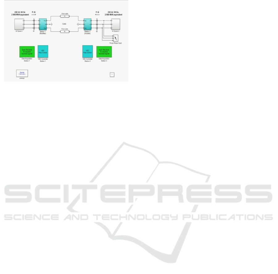
Figure 2: Simulation
These tests ensure that the HVDC system can
handle unexpected disruptions and maintain stable
operation. Overall, this HVDC transmission system
exemplifies advanced electrical engineering
techniques used to achieve efficient long-distance
power transmission.
4 CONCLUSIONS
In conclusion, the proposed multilevel Voltage
Source Converter (VSC) for High Voltage Direct
Current (HVDC) systems with an integrated
Uninterruptible Power Quality Conditioner (UPQC)
presents a significant advancement in power
transmission technology. By utilizing series full-
bridge submodules and reducing component count,
this VSC design offers enhanced efficiency,
reliability, and improved power quality for HVDC
systems. The innovative control strategies
implemented ensure stable operation by dynamically
managing both active and reactive power, while
maintaining voltage balance across the capacitors.
The incorporation of UPQC further strengthens the
system’s ability to mitigate voltage sags, swells, and
harmonics, ensuring high-quality power delivery.
Additionally, the reduced DC-link voltage stress and
soft-switching operations contribute to the overall
efficiency and longevity of the system. The design
has been validated through simulations and
experiments, demonstrating its effectiveness in real-
world scenarios. Ultimately, this VSC design
contributes to the ongoing efforts to enhance HVDC
transmission technology, making it more adaptable to
modern energy demands, particularly in the context
of integrating renewable energy sources. Its
scalability, reliability, and cost-effectiveness offer a
viable solution for future power grid applications.
REFERENCES
Alam, S. J., & Arya, S. R. (2020). Control of UPQC based
on steady state linear Kalman filter for compensation of
power quality problems. Chinese Journal of Electrical
Engineering, 6(2), 52–65.
https://doi.org/10.23919/cjee.2020.000011
MMansor, M. A., Hasan, K., Othman, M. M., Noor, S. Z.
B. M., & Musirin, I. (2020). Construction and
Performance Investigation of Three-Phase Solar PV
and Battery Energy Storage System Integrated UPQC.
IEEE Access, 8, 103511–103538.
https://doi.org/10.1109/access.2020.2997056.
Shi, S., Liu, D., & Han, J. (2024). Small Signal Modeling
and Performance Analysis of Conventional- and Dual-
UPQC. IEEE Access, 12, 11909–11925.
https://doi.org/10.1109/access.2024.3355590.
Sarita, K., Kumar, S., Vardhan, A. S. S., Elavarasan, R. M.,
Saket, R. K., Shafiullah, G. M., & Hossain, E. (2020).
Power Enhancement With Grid Stabilization of
Renewable Energy-Based Generation System Using
UPQC-FLC-EVA Technique. IEEE Access, 8,
207443–207464.
https://doi.org/10.1109/access.2020.3038313.
Yu, J., Xu, Y., Li, Y., & Liu, Q. (2020). An Inductive
Hybrid UPQC for Power Quality Management in
Premium-Power-Supply-Required
Applications. IEEE Access, 8, 113342–113354.
https://doi.org/10.1109/access.2020.2999355.
Han, J., Li, X., Jiang, Y., & Gong, S. (2021). Three-Phase
UPQC Topology Based on Quadruple-Active-Bridge.
IEEE Access, 9, 4049–4058.
https://doi.org/10.1109/access.2020.3047961.
ZHAO, X., ZHANG, C., CHAI, X., ZHANG, J., LIU, F., &
ZHANG, Z. (2018). Balance control of grid currents for
UPQC under unbalanced loads based on matching-ratio
compensation algorithm. Journal of Modern Power
Systems and Clean Energy, 6(6), 1319–1331.
https://doi.org/10.1007/s40565-018-0383-7.
Bilal Ahmad Mattoo, & Abdul Hamid Bhat. (2022).
Comparative Analysis of Various PWM Techniques for
Voltage Source Inverter.
https://doi.org/10.1109/stpes54845.2022.10006650.
Nhlanhla Mbuli. (2023). Dynamic Voltage Restorer as a
Solution to Voltage Problems in Power Systems: Focus
on Sags, Swells and Steady Fluctuations. Energies,
16(19), 6946–6946.
https://doi.org/10.3390/en16196946.
Hariri, A., & M. Omar Faruque. (2014). Impacts of
distributed generation on power quality.
https://doi.org/10.1109/naps.2014.6965404.
Multilevel Voltage Source Converter for HVDC Transmission System
139
