
Study on the Influence of Water Stop Failure on Seepage
Characteristics of High Concrete Face Rockfill Dam
Shengjie Di
1,* a
, Jing Liu
1
and Jiaqi Xu
2
1
Northwest Engineering Corporation Limited, Power China, Xi'an, Shaanxi, 710065, China
2
Hohai University, Nanjing, Jiangsu, 210098, China
Keywords: Concrete Face Rockfill Dam, Osmotic Stability, Stop Water Damage.
Abstract: Aiming at the problem of seepage stability of concrete face rockfill dam, this paper combines the
independently developed Northwest Hydropower Earth-rock Dam Seepage Calculation Platform to carry out
finite element calculation and analysis on the influence of water stop failure on seepage characteristics of dam
body under different schemes. The results show that when the water stop of the panel joint is completely
invalid, the parameters such as water level seepage in the dam body are significantly increased compared with
the complete water stop of the panel joint. The failure water head distribution in the middle of the panel joint
is close to that of the middle and high failure, indicating that the middle failure is more dangerous than the
failure of the higher and lower positions of the panel joint.
1 INTRODUCTION
As a new type of earth-rock dam developed in recent
decades, concrete face rockfill dam has been
recognized by scholars at home and abroad because
of its good safety, wide adaptability, convenient
construction and local materials, and has been widely
used in water conservancy and hydropower projects
at home and abroad (
Chen et al., 2011). According
to the actual operation state of a large number of face
rockfill dams that have been built, the seepage
stability problem is prominent due to the panel
rupture, joint opening and water stop failure caused
by dam deformation and uneven settlement, which
affects the normal operation of the project and even
affects the dam safety or dam failure (
Pan et al.,
2008
). This phenomenon is more obvious for high
dams. Therefore, seepage stability analysis is of great
significance for the long-term safe and stable
operation of CFRD (Xiong
et al., 2015; Lin et al.,
2012; Shakya et al., 2019).
With the development of modern computing
technology and the powerful computing power of
computer, numerical simulation method has become
a
https://orcid.org/
0009-0003-2095-6560
one of the important methods for seepage stability
analysis of concrete faced rockfill dam. In this paper,
the influence of concrete panel water-stop joint
failure on the seepage characteristics of dam body is
studied by using the Northwest Hydropower-rock
Dam Seepage Calculation Platform (NWHDSCP)
developed by the author 's project team, which
provides a basis for evaluating the safety and stability
of dam body and structural design and optimization
design.
2 BASIC THEORY OF
SATURATED-UNSATURATED
SEEPAGE
The basic differential equation of unsaturated
seepage is derived by the same method as saturated
seepage under the assumption that Darcy 's law is also
applicable to unsaturated seepage. The basic
differential equation of unsteady saturated-
unsaturated seepage is as follows:
208
Di, S., Liu, J., Xu and J.
Study on the Influence of Water Stop Failure on Seepage Characteristics of High Concrete Face Rockfill Dam.
DOI: 10.5220/0013627800004671
In Proceedings of the 7th International Conference on Environmental Science and Civil Engineering (ICESCE 2024), pages 208-212
ISBN: 978-989-758-764-1; ISSN: 3051-701X
Copyright © 2025 by Paper published under CC license (CC BY-NC-ND 4.0)

()
3
() ()
ss
cc
ij r c i r c c s
ij
hh
kk h k k h Q C h S
xx t
β
∂∂
∂
+−= +
∂∂ ∂
(1)
where,
c
h
is pressure head.
s
ij
k
is saturated
permeability coefficient tensor.
3
s
i
k
is the permeability
coefficient value in the saturated permeability
coefficient tensor is only related to the third
coordinate axis.
r
k
is relative water permeability.
C
is
moisture capacity.
β
is Saturated-unsaturated
selection constant.
s
S
is elastic specific storage. Q is
source term.
Considering rainfall infiltration, the definite
conditions of the unsteady saturated-unsaturated
seepage differential equation include initial
conditions and boundary conditions, which are
briefly described as follows:
() ( )
3,2,1,,0,
0
== itxhxh
icic
(2)
() ()
txhtxh
icic
,,
1
1
=
Γ
(3)
2
3
() ()
ss
c
ij r c i r c i n
j
h
kk h k k h n q
x
Γ
∂
−+ =
∂
(4)
3
3
() () 0
ss
c
ij r c i r c i
j
h
kk h k k h n
x
Γ
∂
−+ ≥
∂
(5)
()
4
3
() ()
ss
c
ij r c i r c i r
j
h
kk h k k h n q t
x
Γ
∂
−+ =
∂
(6)
where,
i
n
is outer normal direction cosine of
boundary surface.
0
t
is initial time.
1
c
h
is known water
head.
n
q
is known flow.
()
r
qt
is rainfall infiltration
flow.
1
Γ
is deterministic hydraulic head boundary.
2
Γ
is known flow boundary.
3
Γ
is rainfall infiltration
boundary.
4
Γ
is saturated escape surface boundary.
Taking the earth dam as an example, the
schematic diagram of the seepage boundary
conditions in Figure 1.
Figure 1: The schematic diagram of seepage boundary.
3 SIMULATION PROCESS
NWHDSCP is developed based on Intel Visual
Fortran, and its process includes three parts : pre-
processing, calculation and post-processing. The
process diagram is shown in Figure 2.
The pre-processing section includes grid file
IIIN.dat, constraint file IIID.dat, material file
IMAT.dat, earth-rock dam calculation preparation
file FILESET.dat and seepage calculation process file
ISEEP.dat. In the calculation plate, the finite element
calculation principle, convergence criterion and
boundary condition processing method are used to
calculate and analyze the files that have been
generated in the pre-processing plate. The platform
has a perfect post-processing interface. The results
show that the results are closely combined with the
needs of engineers. In addition to the basic
displacement and stress cloud diagram, it also
includes parameters closely concerned in engineering
such as seepage flow of different materials and
settlement velocity of soil filling.
Figure 2: NWHDSCP Simulation process.
4 RESEARCH SCHEME AND
ANALYSIS MODEL
4.1 Research Scheme
The project is a concrete face rockfill dam. The
elevation of the foundation surface is 3711.50 m, the
elevation of the dam crest is 3900.50 m, the width of
the dam crest is 10.0 m, the total length of the dam
Study on the Influence of Water Stop Failure on Seepage Characteristics of High Concrete Face Rockfill Dam
209
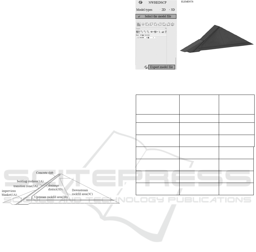
crest is 510.0 m, and the maximum dam height is
189.0 m. The slope ratio of the upstream dam slope
is 1:1.4, and the cover weight area and the upstream
cover area are set at the elevation of 3797.00 m. The
slope ratio of the downstream dam slope is 1: 1.5
above the elevation of 3848.50 m, and 1:1.4 below
the elevation of 3848.5. The calculation condition
adopts the normal storage level condition, the
upstream water level is 3892.00 m, and the
downstream water level is 3721.81 m. The dam body
partition and typical section diagram are shown in
Figure 3. The research scheme are as flollws.
Scheme 1(S-1): The waterstop system is in good
condition.
Scheme 2(S-2): All panel joints fail.
Scheme 3(S-3): The local failure of the panel joint
is 5m long, which is located at the dam height of 5m,
100m and 180m.
Scheme 4(S-4): The local failure of the panel joint
is 5 m long, which is located at 180 m high of the
dam.
Scheme 5(S-5): The local failure of the panel joint
is 5 m long, which is located at 100 m high of the
dam.
Scheme 6(S-6): The local failure of the panel joint
is 5 m long, which is located at 5 m high of the dam.
Figure 3: Computed profile diagram.
4.2 Analyze the Model and Parameters
The typical calculation section diagram of the upper
section is simplified, and the three-dimensional
model is established and meshed by NWHDSCP.A
total of 5 panels ( single width 12m ) are established.
The length of the model is 2307m, of which the
length above the dam axis is 1152m, and the dam axis
is 1155m below the dam axis. The bottom elevation
of the model is taken to 2918.5m elevation, and the
depth of the intercepted dam foundation is about 4
times the maximum dam height, which meets the
requirements of finite element calculation. The model
is divided into 488900 mesh elements and 518271
nodes. The three-dimensional model and grid
diagram are shown in Figure 4 and Table 1.
Figure 4: Finite element analysis model.
Table 1: permeability coefficient of each material area.
Material
Permeability
coefficient(cm/s
)
Allowable
hydraulic slope
of landside
Concrete slab
1.00×10
-7
200.00
Bedding cushion
(2A)
5.83×10
-4
0.25
Transition zone
(
3A
)
5.39×10
-4
0.20
Upstream rockfill
area (3B)
2.14×10
-2
\
Downstream
rockfill area (3C)
2.07×10
-3
\
Impervious blanket
(
1A
)
1.00×10
-5
\
Drainage district
(
3D
)
5.00×10
-1
\
4.3 Hydraulic Gradient of Each
Material Partition
According to the flow velocity value of each material
partition, the maximum hydraulic gradient of each
calculation scheme is calculated, and the analysis
results are shown in Table 2. It can be seen from the
table that when the local water stop failure occurs in
the face joint, the cushion and the transition material
play a certain role in retaining water, and the
maximum hydraulic gradient value increases
significantly. The maximum gradient of the cushion
and the transition material is 3.8 and 0.8; when all the
water-stop joints fail, the anti-seepage ability of the
cushion and the transition material is insufficient, the
water level line inside the dam body rises obviously,
the maximum hydraulic gradient value is greater than
the local failure, and the maximum gradient of the
cushion and the transition material is 14.86 and 2.27.
ICESCE 2024 - The International Conference on Environmental Science and Civil Engineering
210
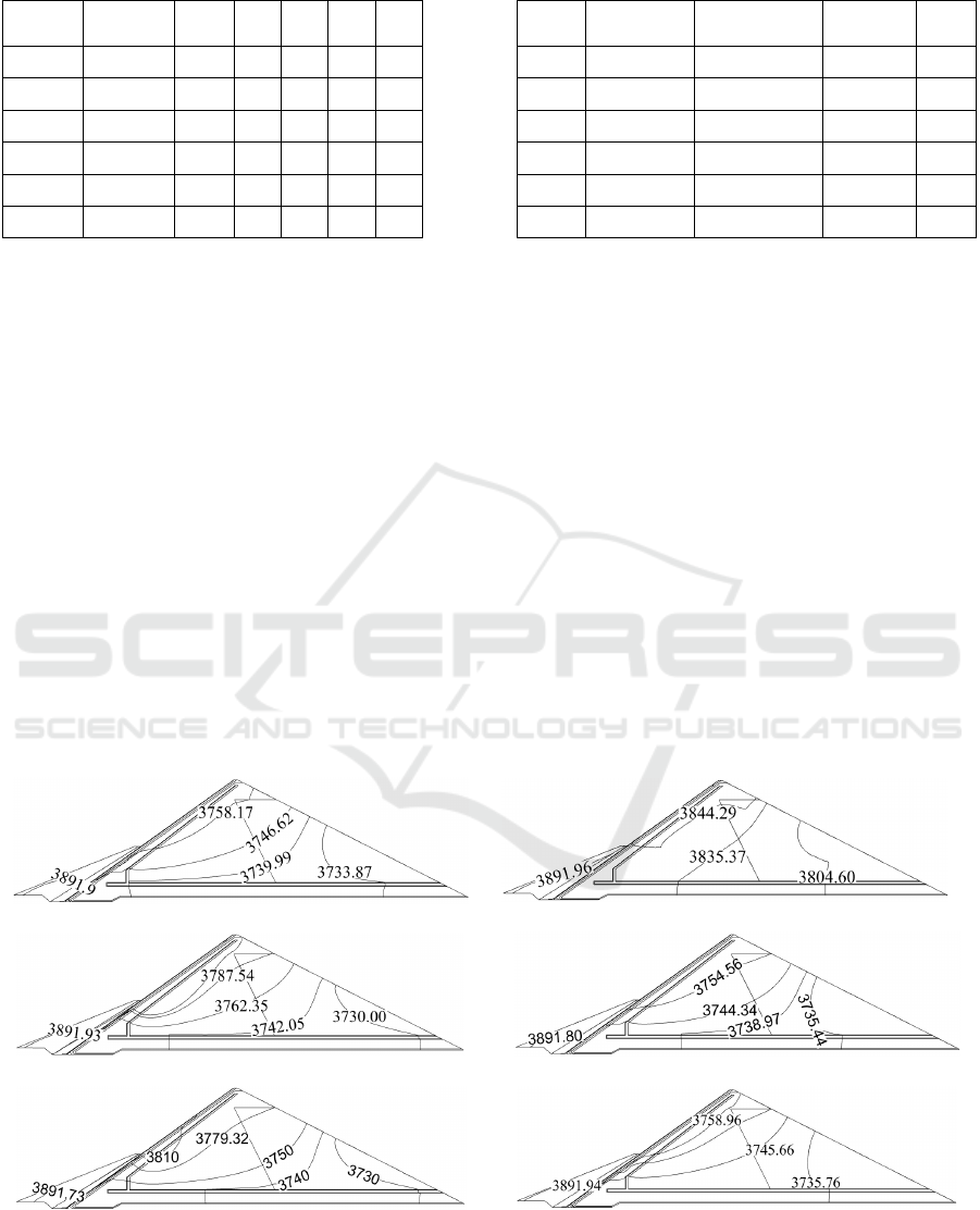
Table 2: Permeability coefficient of each material area.
Scheme
Concrete
slab
2A 3A 3B 3C 3D
S-1 150.60
0.03 0.02 0.04 / 0.07
S-2 34.20
14.86 2.27 0.05 0.18 0.09
S-3 146.80
3.81 0.81 0.04 / 0.52
S-4 150.60
0.03 0.03 0.04 / 0.10
S-5 149.10
2.93 0.65 0.04 / 0.42
S-6 149.40
0.03 0.03 0.04 / 0.11
4.4 Seepage Flow in Each Partition
The calculation section of seepage flow is divided
into three sections : dam body, anti-seepage curtain
and bedrock. The seepage flow of each partition
under each calculation scheme of concrete face
rockfill dam is shown in Table 3. It can be seen from
the table that when all the panel joints fail, the
seepage flow through the dam increases sharply, and
is significantly higher than the local failure. When the
water stop at the bottom of the panel joint fails, the
seepage flow through the dam body is significantly
lower than that in the middle and high parts. The main
reason is that the cover and cover weight on the
upstream side of the dam body play a certain anti-
seepage role, and the water stop failure of the panel
joint has little effect on the seepage flow of the anti-
seepage curtain and bedrock in Figure 5.
Table 3: Permeability coefficient of each material area.
Scheme
Concrete
slab
Impervious
curtain
Bed rock Total
S-1 0.5 12.5 2.9 15.9
S-2 1548.0 11.7 2.8 1562.5
S-3 323.1 10.4 2.6 336.1
S-4 104.3 12.5 2.9 119.7
S-5 317.3 10.4 2.6 330.3
S-6 10.2 12.5 2.9 25.6
4.5 Analysis of Dam Head
When the panel joint is used normally, the water head
in the dam body is significantly reduced, and the anti-
seepage effect of the panel is obvious. When all the
panel joints fail, the water head in the dam body is
large and decreases slowly along the flow direction;
when the height of the panel joint fails, the water head
is dense near the failure position, and the water head
in the dam body is higher in the upstream rockfill area,
but it decreases rapidly along the flow direction. The
distribution of failure water head in the middle of the
panel joint is close to that of the middle and high
failure, which indicates that the middle failure is
more dangerous than the higher position of the panel
joint and the lower position of the upstream
blanketing effect. When the water stop at the bottom
of the panel joint fails, it has little effect on the water
head in the dam body.
(a) S-1. (b) S-2.
(c) S-3. (d) S-4.
(e) S-5. (f) S-6.
Figure 5: Equal water head isoline map.
Study on the Influence of Water Stop Failure on Seepage Characteristics of High Concrete Face Rockfill Dam
211

5 CONCLUSION
When all the water stops of the panel joints fail, the
water level line in the dam body rises obviously,
which is much higher than the action range of the
drainage body. There is also a saturated zone in the
downstream rockfill area, and the seepage flow
through the dam body increases sharply. The
maximum slope of the cushion and the transition
material reaches 14.86 and 2.27.
When the height and height of the face slab joint
fail, the water level in the dam body increases
significantly in the upstream rockfill area, but soon
decreases to the range of the drainage body, and the
maximum slope of the cushion and transition material
is 3.8 and 0.8 ; the distribution of failure water head
in the middle of the panel joint is close to that of the
middle and high failure, indicating that the middle
failure phase is more dangerous than the higher
position of the panel joint and the lower position of
the upstream blanketing effect.
ACKNOWLEDGMENTS
This work was financially supported by the National
Key Research and Development Program of China of
Northwest Engineering Corporation Limited, Power
China. In the meantime, we express thanks to our
colleagues for their help and technical support.
REFERENCES
Chen, S.K, Yan, J, Li, J.M., 2011. Seepage field 3D finite
element simulation of concrete faced rockfill dam
under failure condition of vertical fracture. Rock and
Soil Mechanics, (11): 3473-3478.
Pan, S.H, Mao, X.Y., 2008. Seepage field finite element
simulation of faced rockfill dam under cases of vertical
joints and seal failure. Rock and Soil Mechanics,
29(S1): 145-148.
Xiong, L, Dang, F.N, Zhang, H.F., 2015. Seepage field
analysis of a concrete face rockfill dam after water stop
failure. Water Resources and Power, 33(06): 80-83.
Lin, Q.M, Gong, J., 2012. Analysis of influence of panel
cracking on seepage characteristics of concrete face
rockfill dam. Jilin Water Resources, (10): 1-4.
Shakya, C, Luo, X.Q., 2019. Coupling Internal Erosion
through Concrete Face Rockfill Dams with Damage in
Face Slab under Impounding. Journal of Physics:
Conference Series, 1176(5): 052067(13app).
ICESCE 2024 - The International Conference on Environmental Science and Civil Engineering
212
