
Applicability of Recycled Overlay Structure of Old Cement Pavement
in Road Network
GuoShi Chen
1a
, Hui Huang
2,3,4,* b
and Guanhai Huang
1c
1
Guangxi Zhuang Autonomous Region Highway Development Center, Nanning 530028, China
2
Guangxi Transportation Science and Technology Group Co., Ltd., Nanning 530007, China
3
Guangxi Key Lab of Road Structure and Materials, Nanning 530007, China
4
Research and Development Center on Technologies, Materials and Equipment of High Grade Highway Construction and
Maintenance Ministry of Transport, Nanning 530007, China
*
Keywords: Old Cement Pavement; Regeneration Overlay; Green Economy Is Applicable; Applicability.
Abstract: The degree of damage of the old cement pavement is different, and the way of comprehensive utilization and
treatment of the old road will be very different. In this paper, aiming at the problems of insufficient bearing
capacity, uneven strength and reflection cracks after regeneration of old cement pavement, combined with the
actual engineering application investigation, two types of post-regeneration overlay structure of cement
pavement in road network are investigated and studied. The mechanical response of two different structural
types is calculated by finite element simulation, and the mechanical response characteristics of different
structures are compared. The rationality and applicability of the overlay structure of the old cement pavement
are verified, and the green and economical applicable structure of the old cement pavement is recommended.
It can provide a favorable technical reference for the selection of recycled overlay structure of old cement
pavement.
1 INTRODUCTION
Cement concrete pavement is one of the important
forms of highway pavement structure
(JTG D40-
2011, 2011). There will be different degrees of
damage in the use of cement pavement. It is urgent to
discuss and study the recycled overlay structure of
green and economical old cement pavement. The old
cement pavement recycling overlay technology is a
kind of green environmental protection and
economical recycling technology. However, the
irregular cracks in the rubblized structure layer of the
old cement pavement will directly affect the
durability and comprehensive performance of the
overlay structure. The overlay structure layer is one
of the key considerations to prevent crack reflection.
Therefore, how to choose a green and economical
recycling overlay structure to treat the damage of the
old cement pavement is particularly important (JTJ
a
https://orcid.org/0009-0005-2474-5204
b
https://orcid.org/
0000-0002-0592-3328
c
https://orcid.org/
0009-0000-0393-8342
2 INVESTIGATION AND
RESEARCH ON THE USE OF
RECYCLED OVERLAY
STRUCTURE OF CEMENT
PAVEMENT
In order to deeply understand the effect of various
treatment methods of recycled overlay after
rubblization of old cement pavement, this paper
selects two different overlay structure sections of a
representative road network highway for
comprehensive information and road condition
investigation. The comprehensive information of
different overlay structure sections is shown in Table
1, and the on-site road conditions are shown in Figure
1. Combined with the comprehensive information of
Chen, G., Huang, H., Huang and G.
Applicability of Recycled Overlay Structure of Old Cement Pavement in Road Network.
DOI: 10.5220/0013627200004671
In Proceedings of the 7th International Conference on Environmental Science and Civil Engineering (ICESCE 2024), pages 189-195
ISBN: 978-989-758-764-1; ISSN: 3051-701X
Copyright © 2025 by Paper published under CC license (CC BY-NC-ND 4.0)
189
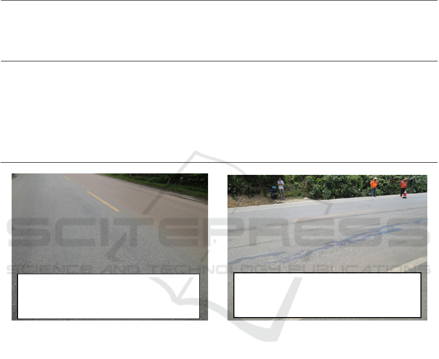
the road section and the on-site road conditions, it can
be seen that the application effect of the asphalt
pavement structure of the old cement pavement
rubblization overlay ATB asphalt macadam base is
good, but the asphalt pavement structure of the old
cement concrete pavement rubblization overlay lime
aggregate base has appeared rutting, longitudinal
cracks, oil and other diseases.
Table 1: Two different overlay structure section comprehensive information questionnaire.
ser
ial
nu
mb
er
Sec
tion
nu
mb
er
pavement structure types
Daily
traffic
volume
(vehicle
s )
Percent
age of
heavy
traffic
(%)
in the
years
already
spent
(years)
Plate
corner
deflectio
n value
(μm)
load
transfe
r
coeffic
ient(%
)
Road
condition
s
1
G3
24
8cm asphalt concrete + 7cm asphalt concrete
ATB-25 + 1cm lower seal layer + rubblized layer
of old cement pavement + 17cm lime-fly ash
stabilized crushed stone + 17cm graded crushed
stone
14407
52 6 79.6 82.7 good
2
G3
24
7cm asphalt concrete + 20cm lime stabilized
aggregate + 1cm sealing oil layer + old cement
pavement rubblization layer + 20cm cement
stabilized gravel + 20cm graded gravel
6340 30 5 88.7 79.2
Rutting,
longitudi
nal joints
and
oiling
Figure 1: Two different overlay structure field survey road map.
3 COMPARATIVE
CALCULATION STUDY ON
RECYCLED OVERLAY
STRUCTURE OF CEMENT
PAVEMENT
3.1 The Finite Element Calculation
Method of Recycled Overlay
Structure of Cement Pavement
In order to grasp the mechanical properties of the
recycled overlay structure of cement pavement, this
paper establishes a three-dimensional pavement
structure model by ABAQUS finite element software
based on the structure of the above two on-site
investigation sections, as shown in Figure 2. The first
structure is paved with 8cm asphalt concrete +
7cmATB-25. Structure 2 is paved with 7 cm asphalt
concrete + 20cm lime stabilized aggregate. The
simulation parameters are shown in Table 2 and 3 (
Xu
et al., 2009; Cao et al, 2010; BEREBJI et al., 2022).
G324 8cm asphalt concrete+7cm
asphalt concrete ATB-25 + old cement
pavement rubblized layer pavement
G324 7cm asphalt concrete + 20cm
lime stabilized aggregate + old cement
pavement rubblized layer pavement
ICESCE 2024 - The International Conference on Environmental Science and Civil Engineering
190

Table 2: Structure-pavement material and its calculation parameters.
name of the material
Thickne
ss
/cm
elastic
Modul
us
/MPa
poisson rat
io
New overlay structure layer
bituminous concrete facing membrane 8 1600 0.25
ATB-25 7 1500 0.25
Old cement pavement struc
ture
Rubblization layer of old cement paveme
n
t
24 1200 0.25
lime-fly ash stabilized-crushed-stone foun
dation
17 1000 0.25
gravel-sorted
subbase
17 500 0.35
earth base / 60 0.35
Table 3: Structural two-surface material and its calculation parameters.
name of the material
Thicknes
s
/cm
elastic
Modulu
s
/MPa
poisson rati
o
New overlay structure layer
b
ituminous concrete facin
g
membrane 7 1000 0.25
Lime stabilized
g
ranular la
y
e
r
20 600 0.25
Old cement pavement struct
ure
Rubblization layer of old cement pave
men
t
24 1200 0.25
cement stabilized macadam base 20 2400 0.25
gravel-sorted
subbase
20 500 0.35
earth base / 60 0.35
In order to simplify the calculation, the model size
is proposed to be 5m × 5m × 5m. The following
assumptions are made for each structural layer: (1)
each structural layer is a uniform, continuous and
isotropic linear elastic body; (2) The layers of each
structure are continuous; (3) The bottom of the
foundation adopts fixed constraint, the displacement
is zero, the side adopts horizontal constraint, the
horizontal displacement is zero; (4) The load is a
single wheel load, the wheel pressure is 0.7 MPa, and
the diameter of the load area is 30.2 cm;(5) The finite
element model mesh is divided by C3D8R (three-
dimensional hexahedron eight-node linear reduced
integral isoparametric element) element, and the seed
treatment is encrypted near the load area (
AZAD et al.,
2020; FEI et al., 2024
).
Applicability of Recycled Overlay Structure of Old Cement Pavement in Road Network
191
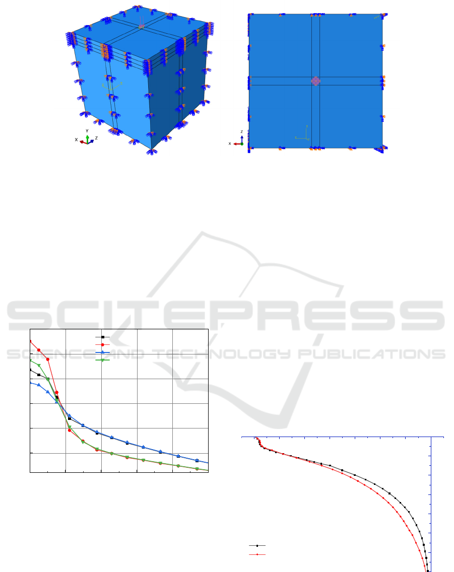
Figure 2: Pavement structure finite element model diagram.
3.2 Comparative Analysis of Finite
Element Calculation of Recycled
Overlay Structure of Cement
Pavement
(1) Deflection
Deflection can reflect the overall bearing capacity of
the pavement. In this paper, the surface deflection of
two different asphalt overlay structures and the
bottom deflection of asphalt overlay are calculated
respectively. The results are shown in Figure 3.
0.0 0.2 0.4 0.6 0.8 1.0
-0.15
-0.20
-0.25
-0.30
-0.35
-0.40
Deflection/mm
Lateral distance from the center of the load/m
The road table of Structure 1
The road table of Structure 2
Asphalt overlay bottom of Structure 1
Asphalt overlay bottom of Structure 2
Figure 3: Deflection comparison diagram of the two
structures.
It can be seen from Figure 3 that at the center of
the load, the maximum deflection of the structure 2 is
much larger than the maximum deflection of the
structure 1, and the maximum deflection value is
shown in Table 4. Compared with structure 1, the
maximum deformation of surface deflection and
bottom deflection of asphalt overlay of structure 2
increased by 18.22 % and 15.49 % respectively. This
shows that the deflection is mainly determined by the
modulus of the new overlay structure. The structure 1
with 8cm asphalt concrete + 7cmATB-25 has better
pavement bearing capacity.
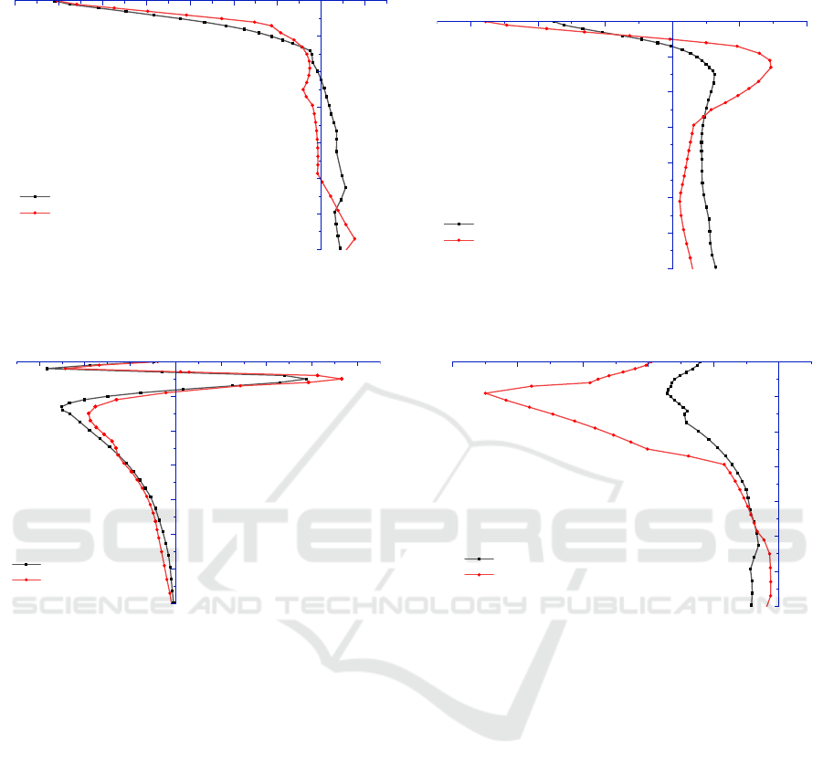
(2) Internal stress of structure
Figure 4: Load center transverse stress contrast diagram.
70
60
50
40
30
20
10
-700 -600 -500 -400 -300 -200 -100 0
Vertical stress of load center/KPa
Depth/cm
Structure 1
Structure 2
Figure 5: Vertical stress comparison diagram of load
center.
ICESCE 2024 - The International Conference on Environmental Science and Civil Engineering
192
70
60
50
40
30
20
10
-700 -600 -500 -400 -300 -200 -100 0 100
Longitudinal stress of load center/KPa
Depth/cm
Structure 1
Structure 2
Figure 6: Longitudinal stress comparison diagram of load
center.
70
60
50
40
30
20
10
-0.6 -0.4 -0.2 0.0 0.2 0.4 0.6 0.8
Shear stress of load center/KPa
Depth/cm
Structure 1
Structure 2
Figure 7: Load center shear stress comparison diagram.
It can be seen from Figure 4-6 that the first
structure completes the tension and compression
alternation in the rubblized layer of the old cement
pavement, while the second structure only occurs in
the cement stabilized gravel layer of the old pavement.
It can be seen from Figure 5 that the vertical stress of
structure 1 and structure 2 shows the same trend, and
it is always under compression, but the vertical stress
of structure 2 is greater than that of structure 1 at the
same depth. It can be seen from Figure 7 that the
maximum shear stress of the two structures appears at
a depth of 5cm, which is located in the new asphalt
overlay layer, and the maximum shear stress of the
first and second structures is 0.575KPa and 0.731KPa,
respectively. The analysis shows that the overall
thickness of the pavement of the second structure is
thicker, and the elastic modulus of the new overlay
structure layer is smaller, which causes the internal
vertical stress and shear stress of the second structure
to be larger, which will increase the risk of pavement
displacement, rutting and cracking.
(3) Internal strain of structure
70
60
50
40
30
20
10
-300 -200 -100 0 100 200
Transverse strain of load center/10^-6
Depth/cm
Structure 1
Structure 2
Figure 8: Load center transverse strain contrast diagram.
70
60
50
40
30
20
10
-1000 -800 -600 -400 -200 0
Vertical strain of load center/10^-6
Depth/cm
Structure 1
Structure 2
Figure 9: Vertical strain comparison diagram of load center.
It can be seen from Figure 8 to 9 that the transverse
and longitudinal strains of structures 1 and 2 express
to the peak of compressive strain in the road, and
decrease with the increase of depth. Tension and
compression alternate in the new pavement structure
layer and begin to increase until the peak of tensile
strain is reached at 15 cm, and then begin to decrease.
Therefore, on the whole, the effect of setting 8cm
asphalt concrete + 7cmATB-25 is better than that of
setting 7cm asphalt concrete + 20 cm lime stabilized
aggregate.
4 CONCLUSION AND
SUGGESTION
In this paper, the use of two different overlay
structures of ATB-25 layer and lime stabilized
granular layer after the recycling of old cement
pavement after rubblization is investigated and the
Applicability of Recycled Overlay Structure of Old Cement Pavement in Road Network
193

structural mechanical response is calculated. The
following conclusions are obtained :
(1) From the calculation and analysis of the failure
mode and damage mechanism of the pavement
structure, it is found that compared with the
structure one, the maximum deformation of the
surface deflection and the bottom deflection of
the asphalt overlay layer of the structure two
increased by 18.22 % and 15.49 % respectively.
The structure one with 8cm asphalt concrete +
7cmATB-25 has better pavement bearing
capacity. Due to the small elastic modulus of the
new overlay structure layer of the second
structure, the vertical stress and shear stress in
the second structure are larger, which will
increase the risk of pavement lapse, rutting and
cracking. The maximum stress of the second
structure in the transverse and longitudinal
directions is greater than that of the first
structure, which easily leads to a large stress
concentration at the bottom of the base layer in
the second structure, resulting in reflective
cracks in the pavement. The vertical strain of
structure one and structure two is always
compressive strain, and it begins to decrease
after reaching the peak of compressive strain at
10 cm. The peak strain of structure two is much
larger than that of structure one, and the
difference of transverse tensile strain peak is the
largest, and the percentage of difference reaches
134.27 %. Therefore, on the whole, the effect of
setting 8cm asphalt concrete + 7cmATB-25 is
better than that of setting 7cm asphalt concrete +
20cm lime stabilized aggregate.
(2) Based on the actual engineering investigation
and simulation analysis, it is found that
considering the overall thickness and bearing
capacity of the structure, the internal stress and
strain changes of the structural layer, it is
recommended to use the old cement pavement
regeneration overlay structure of the road
network, and adopt the ATB asphalt graded
gravel base asphalt overlay structure with better
flexibility and crack resistance. This paper can
provide good theoretical and application support
for the selection of overlay reconstruction
structure after the regeneration of old cement
pavement in road network.
DECLARATION OF COMPETING
INTEREST
The authors declare that they have no known
competing financial interests or personal
relationships that could have appeared to influence
the work reported in this paper.
ACKNOWLEDGEMENTS
The research of this paper is supported by the ' Field
Scientific Observation Station for Long-term
Performance of Subgrade and Pavement in Guangxi
Transportation Industry ' ( Guijiaokejiaohan [2023
No.513 ) and ' Field Scientific Observation and
Research on Long-term Performance of Large and
Medium Repair Structure of National and Provincial
Trunk Highways ' ( Guijiaobianhan [2022] No.174 ).
REFERENCES
JTG D40-2011, 2011. Specification for Design of Highway
Cement Concrete Pavement[S].People 's
Communications Press.
JTJ 073.1-2001, 2001. Technical Specification for
Maintenance of Highway Cement Concrete Pavement
[S]. People 's Transportation Publishing House.
Wang Songgen, Zhang Yuhong, Huang Xiaoming, et al.,
2007. Guide to the application of rubblization
technology in old cement concrete pavement [M].
People 's Transportation Publishing House.
Huang Hui, Feng Yongping, et al., 2016. Research on the
application of graded crushed stone base in the
rubblization overlay of old cement pavement in
Guangxi [J]. Highway and Motor Transport, (6): 147-
150.
Xu Xinquan, Wu Chuanhai, et al., 2009. Analysis of
Mechanical Properties of Asphalt Overlay on Old
Cement Concrete Pavement [J] Highway and Motor
Transport, (3): 55-58.
Cao Zhiyuan, Zhang Qisen, 2010. Mechanical Response
Analysis of Thin Asphalt Overlay on Old Cement
Concrete Pavement [J]. Highway Engineering, 35(4):
42-46.
BEREBJI M, SARKAR A, 2022. Temperature curling and
gradient of roller-compacted concrete composite
pavements [J]. Construction and Building Materials,
353: 129008.
AZAD A M, TAGHREED K M A, 2020. Flexural behavior
of composite concrete-epoxy-reinforced concrete
beams[J]. Iranian Journal of Science and Technology,
Transactions of Civil Engineering, 44: 549-563.
FEI M, FU W, ZHENG X, et al., 2024. Enhancing cement
composite interface with waterglass modification on
ICESCE 2024 - The International Conference on Environmental Science and Civil Engineering
194

bamboo fiber: a viable and effective approach[J].
Construction and Building Materials, 411: 134338.
Applicability of Recycled Overlay Structure of Old Cement Pavement in Road Network
195
