
Detecting Grouting Quality in Post-Tensioned Prestressed Ducts with
IE Method
Hai Liu
*a
and Lei Xu
CCCC First Highway Consultants Co., Ltd., Xi’an 710075, China
*
Keywords: Grouting Quality, Post-Tensioned Prestressed Ducts, Impact-Echo, Non-Destructive Evaluation.
Abstract: In post-tensioned prestressed bridges, the grouting quality of prestressed ducts is of paramount importance to
the durability and load-bearing capacity of the bridge. Voids within the ducts may allow water and other
corrosive substances to penetrate, leading to corrosion of the steel reinforcement and ultimately affecting the
structural safety of the bridge. Impact-echo (IE) testing, an effective non-destructive evaluation (NDE)
method, enables scientific and accurate assessment of the grouting quality of grouting ducts in pre-stressed
structures without damaging the structure. This paper examines the impact-echo method for assessing
grouting quality in post-tensioned prestressed ducts, confirming its adaptability and reliability for practical
engineering applications.
1 INTRODUCTION
Prestressed concrete structures are widely used in
civil engineering due to their superior mechanical
properties and economic benefits (Sun et al., 2022).
However, the grouting quality within prestressed
ducts directly affects the protection of prestressing
tendons and the long-term performance of the
structures. Traditional testing methods have several
limitations: they are often destructive, making the
sample unusable and increasing costs, and usually
assess only localized areas, missing overall
conditions and latent issues. Furthermore, these
methods depend on subjective human judgment,
leading to variability and lack of precise real-time
data, and are inadequate for detecting hidden internal
defects. NDE technologies provide accurate and real-
time inspection results without damaging materials or
structures, improving safety and cost-effectiveness in
industries like manufacturing and bridge
maintenance. The IE method is a robust non-
destructive evaluation technique, particularly
valuable for assessing concrete structures. It enables
comprehensive evaluations of internal elements
critical for maintenance, safety, and longevity. This
paper investigates the use of the IE method for
a
https://orcid.org/0009-0005-9231-8538
assessing grouting quality in pre-stressed concrete
pipelines (Hsieh and Lin, 2016).
2 THEORETICAL ANALYSIS
2.1 Theoretical Foundation:
Reflections of Three Different
Stress Waves
Impact-Echo (IE) is a non-destructive evaluation
method for concrete and masonry structures, based on
the generation and analysis of transient stress waves
induced by an elastic impact (Cheng et al., 2021). The
instantaneous disturbance (force or displacement)
applied to the surface of a solid propagates internally
in the form of three different stress waves: P-waves,
S-waves, and R-waves. The direction of propagation
of the P-wave is consistent with the direction of
particle vibration, generating compressive or tensile
stress. The S-wave propagates in a direction
perpendicular to the particle vibration, resulting in
shear stress. The R-wave propagates along the surface
of the solid and is a type of inhomogeneous plane
wave formed by the coupling of longitudinal and
transverse waves. Among the stress waves generated
by the impact, the P-wave and S-wave propagate into
Liu, H., Xu and L.
Detecting Grouting Quality in Post-Tensioned Prestressed Ducts with IE Method.
DOI: 10.5220/0013591200004671
In Proceedings of the 7th International Conference on Environmental Science and Civil Engineering (ICESCE 2024), pages 163-167
ISBN: 978-989-758-764-1; ISSN: 3051-701X
Copyright © 2025 by Paper published under CC license (CC BY-NC-ND 4.0)
163
the interior of the solid as spherical wavefronts, while
the R-wave radiates outward along the surface of the
solid. The propagation modes of the three types of
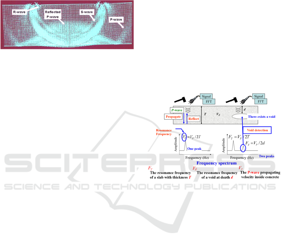
stress waves are shown in Figure 1.
Figure 1: Finite element simulation of impact on a plate
(Carino, 2001).
When a stress wave propagates through a material
and encounters an interface with a different material,
a portion of the incident wave is reflected. The
amplitude of this reflected wave is dependent on the
angle of incidence, achieving its maximum at 90°
(normal incidence). Different types of stress waves
can be clearly distinguished from one another,
providing valuable information about the material
properties. For instance, when the S-wave reaches the
boundary at the bottom of the concrete slab, the
reflected P-wave may have already arrived at the
midpoint of the slab, highlighting the differing
velocities of these wave types. As these waves
interact with interfaces that possess varying acoustic
impedances, they undergo complex phenomena such
as reflection, refraction, and diffraction. These
processes are critical for understanding the internal
structure of the material being tested. Once the waves
are captured by sensors, they undergo thorough
analysis using spectrum analysis techniques. This
involves transforming the time-domain signals into
the frequency domain, which allows for the
assessment of the relationship between the received
signals and the quality of the concrete, thereby
achieving the goal of NDE.
2.2 The Principle of IE Method
The principle of the IE method is that a brief
mechanical impact, such as the strike of a small steel
sphere on a concrete surface, generates low-
frequency stress waves that travel through the
structure and reflect off internal voids and external
boundaries. The transducer near the impact point
captures surface displacements from reflected waves.
The recorded time-domain signals are transformed
into the frequency domain to generate amplitude
versus frequency spectra. When stress waves interact
with the impact surface, voids, and external surfaces,
they cause multiple reflections that result in transient
resonances detectable in these spectra. These
resonances are used to assess the structural integrity
or locate voids within the structure. The principle of
the IE method is illustrated (see Figure 2).
The IE method is capable of detecting voids in
grouted prestressed ducts in various under a majority
of circumstances. However, its performance is
contingent upon several critical factors, including the
geometric configuration of the structure, the
dimensions and morphology of the voids, and the
positioning and arrangement of the prestressed ducts.
Furthermore, external environmental conditions, such
as temperature fluctuations and humidity levels, can
significantly influence the propagation characteristics
of the stress waves and the accuracy of detection
(Losanno et al., 2024; Dethof and Kessler, 2024;
Tang, 2021).
Figure 2: Principle diagram of IE method.
Similar to other defect types, voids within
prestressed ducts may be positioned too deep in a
structure to be detected. The IE signals recorded from
intact concrete, completely grouted ducts, and
partially grouted ducts will exhibit distinct patterns
(JGJ/T 411-2017) (see Figure 3).
2.2.1 Normal Concrete
The principle is similar to that employed in the
Impact-Echo method for detecting the thickness of
concrete slabs. The tests produce distinctive
waveforms and spectra, in which the prominent
characteristics—especially the quantity and
distribution of peaks—are clearly identifiable, as
illustrated in Figure 3 (a). The relationship among the
frequency peak (F
T
), the compression wave velocity
(V
P
) and the echo depth (T) is expressed in the
following equation:
/2
Tsp
FVT
α
=⋅
(1)
ICESCE 2024 - The International Conference on Environmental Science and Civil Engineering
164

Where 𝛼
is a factor equal to 0.96 for a slab
shape.
2.2.2 Fully Grouted Duct
Besides the frequency peak corresponding to the
thickness, there is a higher frequency peak (F
steel
) due
to the existing of tendons as shown in Figure 3 (b).
The reflection of the P-wave will occur from the
tendons within the duct at a frequency of F
steel
, which
can be calculated:
/4
steel s P steel
FVd
α
=⋅
(2)
Where d
steel
is the distance from the impact point
to steel tendons and
P
V
being the P-wave speed in
concrete.
2.2.3 Not Fully Grouted Duct
The reflection from the backside is observed at a
lower frequency than that from the shallower
concrete/flaw interface (refer to Figure 3 (c)). In the
presence of a void in the duct, the frequency
measured will be:
/2
void s P void
FVd
α
=⋅
(3)
Where d
void
is the depth to the void.
When flaws exist in grouted prestressed ducts, the
waveforms and spectra patterns, especially the
spectra, are disrupted and modified. These alterations
provide both qualitative and quantitative information
regarding the presence and location of the flaws.
Figure 3: Impact response of different ducts.
In general, the IE method is favored for its
simplicity and effectiveness, providing a
straightforward approach to quickly and efficiently
detect internal defects in materials and structures. It’s
non-destructive nature and ease of application make
it an ideal choice for assessing the integrity of
grouting quality in post-tensioned pre-stressed ducts
without compromising their usability.
3 FIELD TEST AND
CALCULATION OF THE
EXPECTED FREQUENCY
The post-tensioned concrete bridge was a simply
supported box beam bridge under construction, and
IE method was employed to detect the grouting
quality of the prestressed ducts on-site (see Figure 4).
The lateral ducts, with a cross section of 60×19
mm, were made of corrugated steel tubes. Each duct
contained 3 steel tendons, each~15 mm in diameter.
After the tendons were tensioned, the ducts were
filled with expanded cement grout.
Figure 4: The IE method to detect the grout quality on site.
Testing parameters, including P-wave velocity
and sampling frequency, should be determined before
initiating a new test. The average P-wave velocity
obtained from three measurements was 4050 m/s,
Detecting Grouting Quality in Post-Tensioned Prestressed Ducts with IE Method
165
with a sampling frequency of 60 kHz selected,
yielding 1024 data points per record.
Reflection from the tendons:
For a depth of the steel tendons of 17 cm the
expected frequency is:
f = C
P
/ 4d
steel
= 4050m/s / (4×17cm) =5956 Hz
Reflection from a void in the cable duct:
For a void depth of 14 cm within the duct, the
expected frequency is:
f = C
P
/ 2d
void
= 4050m/s / (2×14cm) =14464 Hz
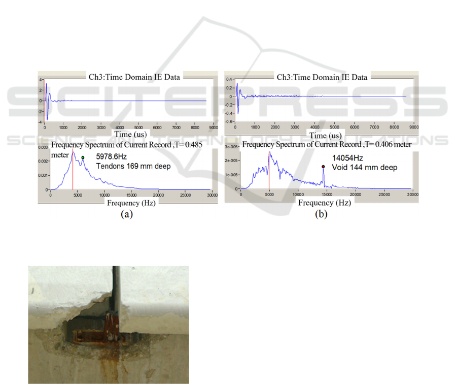
4 RESULTS ANALYSIS
Two tendon ducts were selected for analysis: one that
underwent successful injection without any
discernible issues, and another suspected of
containing voids due to difficulties encountered
during the injection process.
The frequency spectrum of the fully grouted duct
is presented in Figure 5 (a). Upon examination of this
figure, a notable frequency peak at 5978.6 Hz is
observed, which corresponds to a depth of 16.9
centimeters. This peak, in conjunction with the plate
thickness frequency of 4576.1 Hz, representing the
frequency of reflections arriving from the external
surface, provides valuable insights. Importantly, the
depth of 16.9 centimeters aligns precisely with the
actual location of the tendons, which are situated
within a range of 16 to 18 millimeters.
In Figure 5 (b), two prominent frequency peaks
were observed. Notably, the plate thickness
frequency registered at 4988.1 Hz, indicating a depth
of 40.6cm. Yet, the intended thickness of the concrete
structures beneath the impact point was 39cm,
revealing the presence of voids in the tested area. This
discrepancy stems from the extended propagation of
P-waves, a clear indicator of cavities. Furthermore,
theoretical frequencies for voids in the ducts at depths
of 14cm and 18cm were predicted to be 14464 Hz and
11250 Hz respectively. Obviously, the detected
frequency peak of 14054 Hz falls squarely within this
range, confirming the presence of voids within the
grouted tendon ducts.
Figure 5: (a) Impact-echo frequency spectrum at the well-grouted section of cable duct. (b) The waveform and frequency
spectrum of voided duct.
Figure 6: Un-grouted tendon duct.
Indeed, from Figure 6 authenticates these by
showcasing the accurate representation of voids in
un-grouted ducts.
5 CONCLUSIONS
Practical experience demonstrates that the impact-
echo method is effective for detecting voids within
grouted prestressed ducts in post-tensioned
structures. A reliable assessment of internal grouting
quality can be achieved through precise analysis of
the IE signals.
ICESCE 2024 - The International Conference on Environmental Science and Civil Engineering
166

The accuracy of the IE method for detecting post-
tensioned prestressed ducts depends on factors such
as P-wave velocity, the diameter of the steel spheres,
and sampling frequency. Selecting appropriate testing
parameters and employing a suitable mechanical
impact to generate low-frequency stress waves are
crucial for obtaining accurate results. However, in
practical applications, the IE method may face
limitations related to signal attenuation and data
interpretation. To address these challenges, future
research should focus on enhancing signal processing
techniques, improving detection resolution,
developing propagation models for complex
structures, and advancing automated and multimodal
detection systems. These efforts will expand the
applicability and effectiveness of the impact-echo
method in engineering practice.
Assessing the quality of grout injection in tendon
ducts using non-destructive evaluation methods is an
emerging area of study. In China, there are currently
no ideal technologies or standards for this purpose.
Extensive experimental research is required to
calibrate the impact-echo testing method for
assessing the internal grouting condition of
prestressed ducts.
REFERENCES
Sun, B., Yang, Y., Li, X., Yan, M., Xie, M., Bao, Y. 2022.
Full-scale investigation of post-tensioned prestressed
concrete bridge girders subjected to frost heaving in
cold regions. Engineering Structures 250: 113413.
Hsieh, C. T., Lin, Y. 2016. Detecting debonding flaws at
the epoxy-concrete interfaces in near-surface mounted
CFRP strengthening beams using the impact-echo
method NDT & E International 83: 1-13.
Cheng, X., Hong, J., Ma, L., Li, G. 2021. Flexural
performance test of a prestressed concrete beam with
plastic bellows Structural Engineering and Mechanics.
79: 223-235.
Carino, N. 2001. Structures Congress & Exposition
(Washington, D.C. United States) (ASCE) pp. 1-18.
Losanno, D., Galan, S., Parisi, F., Pecce, M. R., Cosenza, E.
2024. Experimental investigation on nonlinear flexural
behavior of post-tensioned concrete bridge girders with
different grouting conditions and prestress
levels. Journal of Bridge Engineering 29: 04023121.
Dethof, F., Kessler, S. 2024. Explaining impact echo
geometry effects using modal analysis theory and
numerical simulations NDT & E International 143:
103035.
Tang, C., Zhang, G., Song, C., Li, X., Hou, Y. 2021.
Flexural behavior of unbonded prestressed concrete
bridge girders Advances in Civil Engineering 1:
6642513
JGJ/T 411-2017 Technical specification for testing of
concrete defects by impact echo method. Industry
Standards of the People's Republic of China. Beijing:
China Architecture & Building Press.
Detecting Grouting Quality in Post-Tensioned Prestressed Ducts with IE Method
167
