
The Application Research of Post-Grouting Technology at the Pile
Base in Collapsible Loess Areas
Chuanzhong Feng
a
, Xue Liu and Shaowei Jiang
*
China First Highway Engineering Co., LTD., Beijing 100020, China
*
Keywords Bored Cast-in-Place Pile, Post-Grouting at Pile Base, Collapsible Loess, Pile Shaft Bearing Capacity,
Engineering Application.
Abstract During the construction of bored cast-in-place piles, issues such as grout loss, grout overflow at the pile top,
and the uplift of the reinforcement cage frequently occur, resulting in the pile's bearing capacity failing to
meet the design requirements even after post-grouting. This study investigates the application of post-grouting
technology for cast-in-place piles in collapsible loess formations and addresses its key technical challenges.
It focuses on controlling the grout fluidity at the pile base, preventing the uplift of the reinforcement cage by
installing a steel plate capsule at the pile base, and managing the bearing capacity of the pile after reducing
its length. The composite post-grouting technology was successfully implemented in the realignment project
of National Highway 108 (Xiangfen-Quwo-Houma section). This technology, utilizing three stages—open
grouting, closed grouting, and re-opened grouting—effectively enhanced the bearing capacity of the pile
foundation while controlling grout loss and reinforcement cage uplift. Experimental results indicate that the
vertical compressive ultimate bearing capacity of single piles fully meets design specifications, significantly
improving both the load-bearing performance and construction safety of the pile foundation. This technology
not only reduces pile construction costs but also enhances engineering quality and economic efficiency,
making it highly valuable and promising for broader engineering applications.
1 INTRODUCTION
With the rapid development of infrastructure
construction in China, the use of pile foundation
construction has increased significantly, and the post-
grouting technique at the pile base has been widely
adopted (Xu et al., 2017). However, issues such as
grout loss, grout overflow at the pile top, and the
uplift of the reinforcement cage still occur during
construction, causing the bearing capacity of the pile
to fall short of design requirements even after post-
grouting (Zhou et al., 2021; Tan et al., 2017). Liu
Zhonghua and colleagues, in their analysis of grout
overflow and treatment measures in the Hangzhou
Minghao Building project, pointed out that grout
overflow occurs when the grout rises beyond the
height of the pile (Gong et al., 2023).
During the construction of cast-in-place piles,
grout overflow and reinforcement cage uplift are two
critical issues with complex mechanisms influenced
by the geometric properties of the pile (e.g., pile
a
https://orcid.org/0009-0007-8199-5167
length, pile diameter), geological conditions, and
grouting parameters (Li et al., 2019). Short pile
designs tend to concentrate grouting pressure at the
pile base, leading to rapid upward grout flow and
increasing the risk of overflow. Enlarged pile
diameters expand the grout flow channel, raising the
upward grout height. Moreover, the thickness of the
mud layer around the pile significantly impacts grout
behavior; a thicker mud layer intensifies upward
grout flow, especially in short piles, leading to grout
rise beyond the pile length and resulting in overflow
(Vakili et al., 2021). Therefore, optimizing pile
design, conducting detailed geological investigations,
and carefully adjusting grouting parameters are
crucial to preventing grout overflow.
On the other hand, in the initial stage of cast-in-
place pile construction, the concrete has not yet come
into contact with the reinforcement cage, which
mainly relies on the balance between the buoyant
force of the slurry and its own weight. As concrete
filling progresses, the concrete level rises to the base
136
Feng, C., Liu, X., Jiang and S.
The Application Research of Post-Grouting Technology at the Pile Base in Collapsible Loess Areas.
DOI: 10.5220/0013580900004671
In Proceedings of the 7th International Conference on Environmental Science and Civil Engineering (ICESCE 2024), pages 136-144
ISBN: 978-989-758-764-1; ISSN: 3051-701X
Copyright © 2025 by Paper published under CC license (CC BY-NC-ND 4.0)

of the reinforcement cage, significantly increasing the
risk of uplift due to the added buoyant force (Zhou et
al., 2021). Eventually, as the conduit penetrates the
reinforcement cage, the anchoring force at the base of
the concrete increases, balancing the forces among
the concrete, the slurry buoyancy, and the weight of
the reinforcement cage, effectively preventing uplift.
To address these challenges, optimizing the grouting
process, enhancing construction monitoring, and
timely adjusting construction parameters are
necessary to ensure that the force states at each stage
remain under control, thereby ensuring the quality
and safety of the pile foundation construction.
Post-grouting technology for cast-in-place piles is
a technique in which grout is injected into the base
and sides of the pile through pre-installed ducts once
the pile has reached the required strength. In the loess
regions of Northwestern China, due to its unique
geological conditions, cast-in-place piles are widely
used because of their efficient utilization of soil
bearing capacity and well-established construction
techniques (Yu et al., 2017). Although post-grouting
is highly effective in enhancing side friction
resistance and strengthening the soil layer at the pile
base, the technique's application in loess regions faces
challenges due to the distinctive mechanical
properties of these soils. Some believe its
effectiveness in increasing side resistance in such
areas is limited, which has hindered the widespread
adoption of post-grouting technology at the pile base
(Wan et al., 2019). Despite existing knowledge and
practical achievements, there remain gaps in
understanding its mechanisms, subjective biases, and
deficiencies in analysis methods and precision in
construction techniques. These issues require further
in-depth analysis and study in conjunction with
practical engineering applications.
Based on this background, this paper presents the
developed post-grouting technology for pile bases
and its application in the realignment project of
National Highway 108 (Xiangfen-Quwo-Houma
section). The successful implementation of this
technology has significantly contributed to reducing
project construction costs, minimizing the total cost
over the full lifecycle, and saving overall investments.
Furthermore, this technology can be directly
promoted and applied in various pile foundation
projects, generating considerable economic and
social benefits, with broad application prospects and
significant engineering value.
2 PROJECT OVERVIEW AND
PROBLEMS
2.1 Project Overview
The project design begins near Zhujiageta in
Xiangfen County, Shanxi Province, with a dual four-
lane roadway and a design speed of 80 km/h. The
starting and ending points are designated as K0+000
to K48+723.5, covering a total route length of 48.723
km. The proposed route corridor passes through
Quwo County, an area located in the northern
temperate and warm temperate semi-arid continental
monsoon climate zone. This region experiences
distinct seasons, with cold and dry winters, dry and
windy springs, hot and rainy summers, and cool, clear
autumns.
At the Xiyang Interchange bridge site, the surface
layer consists of Q
3
silt and silty clay, with needle-
like pores and visible large voids. According to the
"Code for Building Construction in Collapsible Loess
Areas," the bridge site is classified as a self-weight
collapsible ground with a collapse grade of Level III
(severe). The thickness of the collapsible soil at this
location ranges from 14.5 to 15.0 meters.
2.2 Project Problem
Addressing the characteristics of collapsible loess, the
key challenges for shortening the length of pile
foundations in situ while ensuring the safety of
existing bridges and enhancing the bearing capacity
of the pile foundations include:
2.2.1 Control of Grout Fluidity in
Post-Grouting at the Pile Base
During the post-grouting process at the pile base
under high pressure, especially when using open split
grouting methods, accurately controlling the flow
direction of the grout poses challenges. The flow path
can easily change with the natural fissures in sandy
soil and gravel layers, increasing the risk of grout
overflow to the surface and causing the grouting
focus to be imprecisely concentrated in the pile base
area. Additionally, adjusting grouting parameters is
difficult, as precise control over pressure and volume
becomes challenging, making it hard to fully comply
with the predetermined design specifications. This
not only increases the fluctuations in the bearing
capacity of individual piles but also limits their
potential for enhancement.
The Application Research of Post-Grouting Technology at the Pile Base in Collapsible Loess Areas
137
2.2.2 Control of Reinforcement Cage Uplift
After Installing Steel Plate Capsules at
the Pile Base
In the construction of bored cast-in-place piles, the
slurry within the hole poses challenges for the
placement of the reinforcement cage equipped with
steel plate capsules, similar to a piston effect that
hinders slurry discharge and increases the difficulty
of lowering the cage (Zhang et al., 2011). Once the
reinforcement cage is in place, excess sediment tends
to accumulate at the bottom of the hole, making
secondary cleaning difficult. This requires precise
control of slurry properties and optimization of
reinforcement cage design in complex geological
conditions such as collapsible loess to ensure smooth
construction. Additionally, introducing efficient
cleaning techniques to minimize the impact of
sediment and ensure the quality and bearing capacity
of the pile foundation is key to enhancing
construction efficiency and engineering safety.
2.2.3 Impact of Shortened Pile Length on
Pile Shaft Bearing Capacity
In collapsible loess areas, once a pile foundation is
subjected to water infiltration, not only is the original
positive friction completely lost, but significant
settlement caused by soil collapse can also induce
negative friction, which results in additional loads
ultimately borne by the soil at the pile tip (Zhang et
al., 2006). If the length of the pile foundation is
shortened at this point, it will further weaken the
bearing capacity of the pile shaft, significantly
impacting the overall stability of the bridge structure
and increasing structural safety risks (Xi et al., 2022).
Therefore, when designing pile foundations in
collapsible loess regions, it is essential to fully
consider the risks of water infiltration and the
reasonableness of the pile length to ensure the
stability and safety of the bridge.
3 TECHNICAL CONTENTS
3.1 Composite Post-Grouting
Technology of Pile Bottom
Pile bottom composite post-grouting is divided into
three stages: open pile bottom grouting, closed pile
bottom grouting and open pile bottom re-grouting.
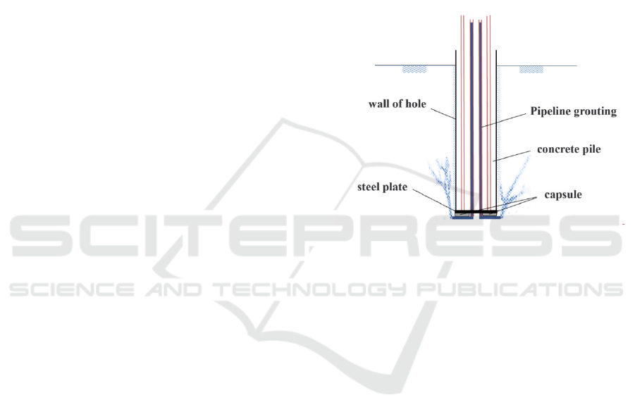
3.1.1 Pile Bottom Open Grouting
Open grouting technology involves injecting the
slurry directly into the soil through a non-blocking
grouting pipe to ensure that the slurry is fully
integrated with the soil, so as to achieve the desired
engineering effect. The slurry is injected into the
sediment and strata at the bottom of the pile, and the
root cement slurry veins are formed at the bottom of
the formation and the side wall of the pile. The
simulation effect diagram of open grouting at the
bottom of the pile is shown in Figure 1.
Figure 1: Simulated Effect of Open Grouting at Pile Bottom
in Soil Layers.
In view of the high pressure required for grouting
after pile bottom, split grouting is usually adopted for
open pile bottom grouting, but it is difficult to control
the grouting area under this method. Driven by high
pressure, the slurry is easy to diffuse disordered along
the natural cracks in sand, soil and gravel layer,
resulting in the grouting focus may not be precisely
concentrated in the pile bottom area. In addition, the
precise control of the pressure and the amount of
grouting becomes a big challenge in the process of
grouting, and it is difficult to strictly follow the design
standards, which affects the stability and consistency
of the grouting effect. Such uncertainty not only
intensifies the fluctuation range of the bearing
capacity of a single pile, but also weakens the stability
and reliability of its bearing capacity improvement
(Zhu, 1998).
3.1.2 Pile Bottom Closed Grouting
The remarkable feature of the closed post-compaction
grouting technology at the bottom of the pile is that
its process design cleverly ties the compression
grouting pipe to the steel cage to ensure the
ICESCE 2024 - The International Conference on Environmental Science and Civil Engineering
138
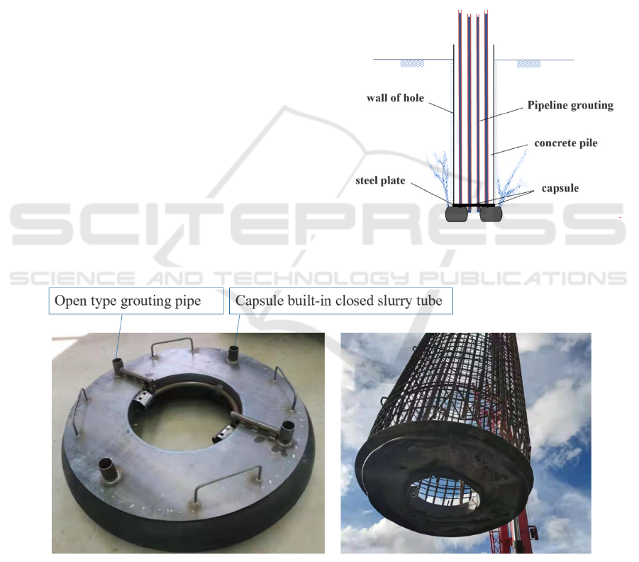
construction of the grouting channel. Especially
critical is the special steel plate capsule installed at
the bottom of the reinforcement cage, which is not
only structurally strong, but also carefully designed to
seamlessly connect with the grouting pipe, realising a
closed and efficient grouting process. This design
enables the grouting operation to be precisely
controlled, and the slurry enters the steel plate capsule
through the grouting pipe under pressure, and then
spreads effectively to the pile bottom and the
surrounding soil layer to achieve the expected effect
of foundation reinforcement, and the simulated effect
of "closed" grouting at the bottom of the pile and the
capsule are shown in Figure 2 and Figure 3.
During the construction process, slurry is injected
into the pre-set capsule at the bottom of the pile
through a precise slurry pipe system, which causes the
capsule to expand uniformly and gradually form a
solid stone enlarged head. This process not only
strengthens the pile base structure, but also cleverly
utilises the expansion force to extensively squeeze
and spread the previously injected cement slurry
around the pile base. This squeezing action prompts
the cement paste to mix with the pile bottom slag in
depth, and after the reaction, a denser cement soil
layer is formed, which effectively improves the
bearing capacity and overall stability of the pile
foundation. The closed post-pressure grouting
technique at the bottom of the pile can quickly and
effectively squeeze and eliminate the slag layer at the
bottom of the pile, and significantly improve the
cleanliness and tightness of the pile bottom area (Teh
et al., 2008; Orr, 2009; Wan et al., 2024). At the same
time, this technique ensures that the injected slurry is
accurately concentrated in the pile bottom, and the
pile bottom and its surrounding strata are compacted
and consolidated in depth by high-pressure action,
which further enhances the stability of the foundation.
In addition, the enlarged head formed during the
grouting process significantly enlarges the support
area of the pile bottom, and this structural
optimisation greatly improves the ultimate bearing
capacity of the pile foundation.
Figure 2: Simulation Diagram of Closed Pressure Grouting
Effect at the Pile Base in Soil Layers.
Figure 3: Plate capsule device picture.
3.1.3 Pile Bottom Open Grouting Again
The composite post-grouting technology at the pile
base integrates both open and closed grouting
techniques, retaining their respective advantages
while overcoming their limitations. Its most notable
feature is the combination of three grouting actions—
fracturing, permeation, and compaction—focused at
The Application Research of Post-Grouting Technology at the Pile Base in Collapsible Loess Areas
139
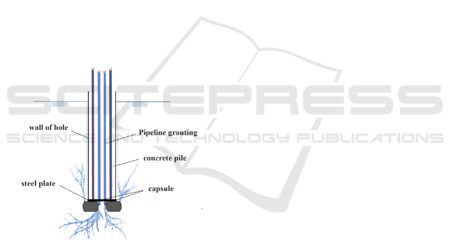
the pile base to work synergistically. The constraints
provided by the ring-shaped capsule at the pile base
effectively implement the "three-point" principle of
grouting, which includes precise control of the
grouting location, volume, and direction. The
simulated effect of this composite post-grouting at the
pile base is illustrated in Figure 4.
The design of the central-hole steel plate capsule
skillfully incorporates multiple functions. Its key
feature is the hole in the center, which plays a crucial
role during the descent of the reinforcement cage.
This design allows the slurry at the bottom of the pile
to pass smoothly through the holes, reducing
resistance to the descent of the reinforcement cage
and ensuring that it reaches the bottom of the hole
without obstruction. Furthermore, if excess sediment
accumulates at the bottom of the hole after the
reinforcement cage has reached its final position,
these holes serve as a secondary sediment removal
channel. Through the holes, the bottom of the pile can
be effectively cleaned, removing any excess sediment
and ensuring the quality and safety of the pile
foundation construction.
Figure 4: Simulation effect of open repressing grouting at
pile bottom in soil layer.
An open grouting pipe is installed in the central
holes to perform open grouting on the soil layers at
the pile base, which can eliminate possible issues at
the bottom of the pile, such as sediment, mud, voids,
and gaps, thereby solidifying the soil layer. Due to the
expansion of the closed grouting capsule, a large plug
is formed at the pile base, preventing the upward
return of the cement grout. The cement grout further
fractures and permeates downward around the pile
base, forming root-like grout veins that enhance the
consolidation effect of the soil layers around the pile
base, extending the reinforcement effect to greater
depths.
3.2 Floating Control Technology of
Steel Bar Cage
To prevent the uplift of the reinforcement cage after
installing a steel plate capsule at the pile base, it is
necessary to implement thorough preventive and
control measures in three areas: the design of the
reinforcement cage structure, the adjustment of
concrete and slurry, and the concrete pouring strategy.
3.2.1 Steel Cage Structure Optimization
Strengthen the straightness of the main reinforcement:
ensure that the main reinforcement of the steel cage is
straight without bending, reduce unnecessary joints,
so as to reduce the friction resistance and lateral
adsorption force generated when the concrete is
poured, and help the stability of the steel cage in the
hole.
Initial anchoring strategy: place the reinforcing
cage precisely on the bottom of the hole, and make
full use of one of the first instant concreting anchoring
effect, increase the reinforcing cage and initial
connection strength of hole wall.
Stirrup spacing adjustment and the orifice fixed:
appropriate increase the intensity of stirrup spacing in
order to optimize the structure of reinforcing cage, at
the same time in the orifice area add back pressure
device, further reinforcing cage position, prevent to
rise.
3.2.2 Concrete and Mud Performance
Management
Reduce the density of the mixed liquid: According to
the principle of buoyancy, the density of the mixed
liquid between the mud and the concrete in the hole
is reduced by precisely regulating the performance of
the mud, thus reducing the buoyancy effect on the
steel cage. Before perfusion, rock cuttings at the
bottom of the hole should be completely removed to
reduce the influence of impurities on the density of
the mixed liquid.
Concrete performance optimization: strictly
control the initial setting time of concrete, make sure
it's in the process of infusion to keep good workability
and liquidity, reduce the friction between the
reinforcing cage and, at the same time guarantee the
quality of concrete.
ICESCE 2024 - The International Conference on Environmental Science and Civil Engineering
140

3.2.3 Fine Perfusion Speed Control
Initial low speed perfusion: When the concrete liquid
surface first contacts the steel cage, the perfusion
speed should be slowed down to reduce the direct
impact force of concrete on the steel cage and avoid
the buoyancy surge resulting in floating.
Speed in stages: reinforced concrete initial setting at
the bottom of the cage, form a stable support, can be
gradually to speed up the infusion speed, to improve
construction efficiency, and ensure the safety of the
infusion process under control.
3.3 Pile Bearing Capacity Control
Technology
3.3.1 Selection of Grouting Mode
In the reinforcement of pile foundation, post-grouting
technology becomes the key because of the high
sensitivity of pile end to sediment (Guang-Yao et al.,
2012). The technology not only strengthens the pile
end sediment and produces bottom expanding effect,
but also the reinforcement effect of the pile end
sediment and soil is much stronger than that of the
pile side mud. Therefore, pile end reinforcement
should be taken as the primary consideration.
According to the Technical code for building pile
foundations (JGJ94-2008), when a single pile end is
grouting, the vertical reinforcement section is set to
be 12 meters above the pile end, which is essentially
focused pile end reinforcement. However, further
analysis shows that if this range is extended to the pile
side area 12 meters above the pile end, the overall
reinforcement effect will be more significant by using
the higher side friction resistance of deep soil.
Therefore, the optimal strategy is to adopt the
combination of pile end and pile side to maximize the
bearing capacity and stability of pile foundation.
3.3.2 Strengthening Mechanism of Post-
Grouting on Pile Side Resistance
In the construction technology of traditional bored
pile, mud wall protection, as a key measure in the
process of hole formation, effectively guarantees the
stability of hole wall and construction safety.
However, the mud crust formed by the gradual
solidification of mud around the hole wall is difficult
to be completely removed in the subsequent concrete
pouring process, thus building a "barrier" between the
pile and the soil. This layer of mud not only changes
the physical properties of pile soil interface, but also
profoundly affects the lateral resistance of pile. The
moisture rich in the mud skin softens the structure of
the adjacent soil under the action of infiltration,
resulting in a significant reduction in the strength of
the soil. At the same time, the mud skin itself has a
lower friction coefficient than the undisturbed soil,
which acts as a "lubricant" between the pile and the
soil virtually, reducing the direct friction contact area
between the pile and the soil, and thus weakening the
generation of pile side friction resistance. In addition,
with the gradual consolidation and hardening of pile
concrete, the mud layer tends to shrink in volume to
varying degrees, which further intensifies the
separation tendency between pile and soil, forming
new micro gaps, and further weakening pile side
resistance (Jia et al., 2011).
At the top of the pile under load, the effect of pile
side grouting can be analogy in around pile to form
an enhanced concentric cylindrical "reinforcing
tape". Through the infiltration and solidification of
the grouting material, the reinforcement belt realizes
the strengthening and integration of the soil on the
side of the pile, and its influence scope extends
roughly to 6 to 10 times the pile diameter. This
expanding effect not only enhances the interaction of
pile-soil interface, but also significantly changes the
stress distribution in soil body. With the formation of
the grouting reinforcement belt, the possible stress
concentration in the soil is relieved, and the shear
stress gradually dissipates and tends to be evenly
distributed within the reinforcement belt. At the outer
edge of the reinforced belt, the shear stress gradually
decreases until it reaches a level close to zero.
4 TECHNOLOGY APPLICATION
In order to test the technical effect, NK0+371.5
Beidong Interworking bridge and LK0+465.3 Xiyang
Interworking bridge of Xiangfen - Quwo - Houma
transit transformation project of National Highway
108 were applied and verified, Figure 5. shows the
installation and welding of the steel cage at the
application site.. The projects are located in Quwo
County, Linfen City, Shanxi Province. The pile body
adopts bored pile. The pile length of Beidong
Interconnecting bridge is 35m, the pile diameter is
1.5m, and the vertical compressive ultimate bearing
capacity of single pile is 16376.04kN. The pile length
of Xiyang interworking bridge is 35m, the pile
diameter is 1.8m, and the designed ultimate bearing
capacity is 13078.73kN.
The Application Research of Post-Grouting Technology at the Pile Base in Collapsible Loess Areas
141

(a) (b)
Figure 5: Installation (a) and welding (b) of steel cage.
Self balancing method to detect the pile bearing
capacity, its core idea is to use special loading
equipment on pile body in the load box, in the process
of pile is based on the test objectives and the
geological conditions of the default in reinforcing
cage in specific depth, then closed pile, at the same
time to ensure the loading box connecting line and
other monitoring equipment smooth extends to the
surface. After the pile body is fully cured, the device
applies pressure to the load box through a ground-
operated pressure system to simulate the stress
situation at both ends of the pile body. In this process,
the load box becomes a force transfer medium,
applying both an upward reaction force (Q
uu
) to the
upper pile and a downward positive force (Q
ud
) to the
lower pile. Since the side friction resistance of the pile
body and the surrounding rock and soil body balance
each other, a self-reaction system is formed, and no
external anchor pile or reaction device is required to
achieve the loading effect equivalent to the traditional
static load test (Cheng and Yu, X., 2013; Xing et al.,
2019).
With the loading force increases gradually, the
upper part of pile body in the reverse display its
bearing capacity under load characteristics, through
the monitoring equipment to record the
corresponding parameters such as displacement,
strain (Q
uu
series); At the same time, the lower pile
reflects its bearing capacity under forward loading,
and the corresponding response parameters are also
recorded (Q
ud
series). Finally, through detailed data
processing and analysis of the mechanical parameters
obtained during the loading process, the bearing
capacity of a single pile foundation can be calculated,
as shown in formula (1) (Murali et al., 2024).
1
uu
uud
QW
QQ
γ
−
=+
(1)
Where: Qu is the vertical compressive ultimate
bearing capacity of single pile /kN; Quu is the
measured ultimate bearing capacity of pile on the
upper section of load box /kN; Measured ultimate
bearing capacity of pile under Qud load box /kN; W
is the dead weight of the pile in the upper section of
the loading box; γ1 is the correction coefficient of pile
side resistance in the upper section of load box, with
a value of 0.9.
According to the results of self-balancing
experiment, the bearing capacity indexes of single
piles at two application points are statistically
calculated as shown in Table 1. The test and analysis
show that the vertical compressive ultimate bearing
capacity of single pile at the two application points
completely meet the design requirements.
ICESCE 2024 - The International Conference on Environmental Science and Civil Engineering
142
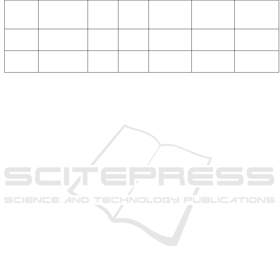
Table 1: Single pile bearing capacity statistics table.
sequence
number
pile foundation
pile
diameter
(m)
pile
length
(m)
Load box
buried
position
Limit value of
bearing
capacity of
p
ile (kN)
Design
bearing
capacity limit
(kN)
1
Beidong
Interconnecting
b
rid
g
e
1.5 35
Pile bottom
up 14.8
meters
Not less than
16515
16376.04
2
Xiyang
Interconnecting
b
rid
g
e
1.5 35
The bottom of
the pile is 7
meters up
Not less than
13316
13078.73
5 RESULT
This project has formed a complete set of technical
achievements in the post-grouting construction of pile
foundation in collapsible loess stratum, such as the
flow control of post-grouting slurry, the floating
control of steel cage after the pile bottom is installed
with steel plate capsule, and the bearing capacity
control of pile body after the length of pile foundation
is shortened. The research results have been
successfully applied in the support project of National
Highway 108 Xiangfen - Quwo - Houma transit line
change, and have played a demonstration role. As the
key basis for pile foundation optimization in loess
area, it is of great significance to improve the level of
bridge construction in our country, and enhance the
innovation ability and technical competitiveness of
bridge construction in our country. The results of the
project have a very positive role in reducing the
construction cost and the total cost of the whole life
cycle of the bridge, and saving the total investment.
The results can be directly applied in the construction
of various bridge projects, and can produce
remarkable economic and social benefits, and has
broad application prospects and important
engineering significance.
6 DISCUSSION
In this study, we successfully applied post-grouting
technology to address common issues in cast-in-place
piles, such as grout loss and reinforcement cage
uplift, in collapsible loess formations. By
implementing a composite grouting method in three
stages—open grouting, closed grouting, and re-
opened grouting—we significantly improved the
piles' bearing capacity and construction safety. The
use of a steel plate capsule at the pile base effectively
controlled grout fluidity and prevented reinforcement
cage uplift. This approach not only enhanced the
load-bearing performance but also reduced
construction costs, demonstrating its potential for
broader engineering applications.
REFERENCES
Xu, X., Yu, J., Xue, L., et al., 2017. Investigation of
Molecular Structure and Thermal Properties of
Thermo-Oxidative Aged SBS in Blends and Their
Relations. Materials, 10: 768.
Zhou, Z., Wang, K., Feng, H., et al., 2021. Centrifugal
model test of post-grouting pile group in loess area. Soil
Dynamics and Earthquake Engineering, 151: 106985.
Tan, Y., Lu, Y., Peng, F., et al., 2017. Post-Grouting of
Long Bored Piles in Clay. 338–347.
Gong, W., Zhang, Z., Lin, Y., et al., 2023. Full-scale field
test study of bearing characteristics of post-grouting
pile for offshore wind turbines. Ocean Engineering,
268: 113451.
Li, J., Shao, S., Shao, S., 2019. Collapsible characteristics
of loess tunnel site and their effects on tunnel structure.
Tunnelling and Underground Space Technology, 83:
509–519.
Vakili, A., Zomorodian, S. M. A., Totonchi, A., 2021.
Laboratory and Three-Dimensional Numerical
Modeling of Laterally Loaded Pile Groups in Sandy
Soils. Iran J Sci Technol Trans Civ Eng, 45: 2623-2636.
Zhou, Z., Xu, F., Lei, J., et al., 2021. Experimental study of
the influence of different hole-forming methods on the
bearing characteristics of post-grouting pile in Loess
Areas. Transportation Geotechnics, 27: 100423.
Yu, J., Huang, M., Li, S., et al., 2017. Load-displacement
and upper-bound solutions of a loaded laterally pile in
clay based on a total-displacement-loading EMSD
method. Computers and Geotechnics, 83: 64-76.
Wan, Z. H., Dai, G. L., Gong, W. M., 2019. Field study on
post-grouting effects of cast-in-place bored piles in
The Application Research of Post-Grouting Technology at the Pile Base in Collapsible Loess Areas
143

extra-thick fine sand layers. Acta Geotechnica, 14(5),
1357-1377.
Zhang, Z. M., He, J. Y., Fang, K., 2011. Experimental study
on size effect of large-diameter bored cast-in-situ piles
with post-grouting in soft soil. Chinese Journal of
Geotechnical Engineering, 33(sup2), 32-37.
Zhang, Z. M., Zhang, G. X., Wu, Q. Y., et al., 2006. Studies
on characteristics of mudcake and soil between bored
piles. Chinese Journal of Geotechnical Engineering.
Xi, P., Kan, M., Chen, L. Q., 2022. Model test and
numerical simulation study on the effect of mudcake
and length-diameter ratio on the bearing capacity of
bored cast-in-place piles. Advances in Civil
Engineering, 2022(Pt.13): 1.1-1.14.
Zhu, F., 1998. Centrifuge modelling and numerical analysis
of bearing capacity of ring foundations on sand.
Dissertation Abstracts International, 60-02: 0757.
Adviser: J. I. Clark..
Teh, K. L., White, D. J., Chow, Y. K., et al., 2008. A
comparison of the bearing capacity of flat and conical
circular foundations on sand. Géotechnique, 58(10):
781-792.
Orr, T., 2009. A comparison of the bearing capacity of flat
and conical circular foundations on sand d. j. white, k.
l. teh, c. f. leung and y. k. chow, géotechnique, 58(10),
781–792. 2008. Géotechnique, 60(2), 147-149.
Wan, Z. H., Duan, C., Hu, T., et al., 2024. Field study on
bearing capacity of large-diameter rock-socketed bored
piles with combined grouting in highly weathered rock
layers. Rock Mechanics and Rock Engineering, 57(10):
8701-8722.
Guang-Yao, L. I., Ke-Lie, Z., Zu-De, L. U., 2012.
Numerical simulation of size effect on bearing capacity
of large diameter rock-socketed piles under different
strengths of surrounding rocks. Rock and Soil
Mechanics, 33: 384-388.
Jia, J. L., Zhou, M., Zheng, J. H., 2011. Experimental study
on bearing behavior of large-diameter overlength cast-
in-place bored pile post-grouting. Advanced Materials
Research, 243-249:3251-3258.
Cheng, R. C., Yu, X., 2013. Experiment research on bored
pile with post-grouting technology. Advanced
Materials Research, 838-841, 854-857.
Xing, H., Liu, L., Luo, Y., 2019. Effects of construction
technology on bearing behaviors of rock-socketed
bored piles as bridge foundations. Journal of Bridge
Engineering, 24(4), 05019002.1-05019002.9.
Murali, A. K., Haque, A., Bui, H. H., 2024. Effect of smear
distribution on the load-bearing mechanisms of rock-
socketed piles in soft rocks. Journal of Geotechnical
And Geoenvironmental Engineering, 150(1),
4023127.1-4023127.14.
ICESCE 2024 - The International Conference on Environmental Science and Civil Engineering
144
