
Design of Energy-Efficient Switched Reluctance Motor Using ANSYS
Software
S. Bhuvaneswari
a
, R. Ramya
b
and V. Srimathi
c
S. A. Engineering College, Anna University, Avadi Road, Tamil Nadu, India
Keywords: Switched Reluctance Motor (SRM), Energy-Efficient Motor Design Finite Element Analysis (FEA) ANSYS
Maxwell, Electromagnetics.
Abstract: This research presents the design of an energy-efficient Switched Reluctance Motor (SRM) using ANSYS
software, aiming to optimize performance and reduce energy consumption. The SRM is recognized for its
robust construction and high efficiency, making it suitable for various applications in electric vehicles and
industrial automation. Switched reluctance motor (SRM’s) are particularly gaining attention in the EV world
for their advantages over traditional motors, such as higher reliability, low material cost, high motor-drive
efficiency. Electric Vehicles (EVs) driven by electric motor reduces the usage of fossil fuel. The model shows
considerable improvement in efficiency and reduction in torque ripple.
1 INTRODUCTION
The Switched Reluctance Motor (SRM) has gained
significant attention in recent years due to its inherent
advantages, such as simplicity, robustness, and high
torque-to-weight ratio. With the growing demand for
energy-efficient solutions in various sectors,
including electric vehicles and renewable energy
systems, optimizing the design of SRMs has become
crucial. Traditional electric motors often face
challenges related to energy losses, inefficiencies,
and thermal management.
This study focuses on enhancing the performance
of SRMs through innovative design strategies using
ANSYS software, a powerful tool for finite element
analysis (FEA). By simulating electromagnetic fields
and analyzing thermal and mechanical stresses, we
aim to refine motor parameters such as rotor shape,
stator configuration, and winding techniques. The
goal is to minimize energy losses, improve efficiency,
and ensure reliable operation across a range of
applications.
In this paper, a phase radial force shaping method
is proposed by using harmonic content analysis. A
generic function for the radial force shape is
identified, whose parameters are calculated by an
a
https://orcid.org/0000-0003-2128-9459
b
https://orcid.org/0000-0008-4155-3310
c
https://orcid.org/0000-0002-5717-1946
optimization algorithm to minimize the torque ripple
for a given average torque. From the phase radial
force profile, a current reference is obtained. The
proposed methodology is experimentally validated
with a four-phase 8/6 SRM through acoustic noise
measurements at different speed and load conditions
(Emadi A, 2019).
A new method to detect the initial rotor position
of switched reluctance machine (SRM) is presented
in this article. Unlike most conventional position
estimation methods, the proposed method does not
need any extra premeasurement and only the data
with finite element method (FEM) are required. First,
a linear regression model (LRM) is presented to
describe the relationship between FEM and measured
inductance characteristics.
Then, to detect the position, the residual sum of
squares of the proposed LRM is considered as an
objective function, which is a convex function with
rotor position. The rotor position can be estimated by
minimizing the objective function with the golden-
section search method. Finally, the accuracy of the
proposed estimation algorithm is validated by the
experimental results on a three-phase 12/8 pole SRM
prototype (Bilgin, 2019).
40
Bhuvaneswari, S., Ramya, R. and Srimathi, V.
Design of Energy-Efficient Switched Reluctance Motor Using ANSYS Software.
DOI: 10.5220/0013575400004639
In Proceedings of the 2nd International Conference on Intelligent and Sustainable Power and Energy Systems (ISPES 2024), pages 40-45
ISBN: 978-989-758-756-6
Copyright © 2025 by Paper published under CC license (CC BY-NC-ND 4.0)

2 DESIGN OF SWITCHED
RELUCTANCE MOTOR
This design approach outlines the steps necessary to
create a 4-phase, 8-pole switched reluctance motor
tailored to your specifications. Each aspect, from
geometry to control strategies, is critical to ensure
efficient operation and desired performance
characteristics.
Here's a detailed design outline for a 4-phase
switched reluctance motor (SRM) with the given
specifications.
2.1 Design Specifications
The following is the design specification of the SRM
motor.
• Phase Count: 4
• Stator Poles: 8
• Rotor Poles: 6 (common choice for 8 stator
poles)
• Phase Resistance (R): 0.96 Ω
• Aligned Inductance (L_aligned): 120 mH
• Unaligned Inductance (L_unaligned): 14
mH
• Phase Current (I_phase): 8 A
• Maximum Phase Voltage (V_max): 400 V
• Torque Inertia (J): 0.053 kg·m²
• Viscous Damping Coefficient (b): 0.008 N·
m·s
• Maximum Speed: 1500 RPM
• Power Output: 5.5 HP (approximately 4.1
kW).
2.2 Motor Geometry
Rotor Configuration is set to 6 poles so to maintain a
good balance with 8 stator poles. Stator and Rotor
Dimensions: The stator is designed with 8 evenly
spaced teeth. The rotor has 6 corresponding poles,
shaped to minimize air gap and enhance magnetic
interaction. The outer diameter, inner diameter, and
length of the stator and rotor based on the power
requirements and thermal considerations are
determined.
2.3 Magnetic Circuit Design
Core Material: Laminated silicon steel for both stator
and rotor to minimize eddy current losses is used.
Air Gap: Air gap is designed so as to optimize
torque production while minimizing losses.
Winding Configuration: Each stator pole will
have a winding. The number of turns can be
calculated based on the desired inductance and
phase current.
Turn Calculation:
Where L = inductance (H)
N = number of turns
μ = permeability of the core material
A = cross-sectional area of the core
(m²)
g = air gap (m)
2.4 Torque Calculation
The average torque can be calculated using the
following formula:
(2)
Where:
T = torque (N-m)
P = power (W) = 4.1 kW
ω = angular speed (rad/s)
For a maximum speed of 1500 RPM:
2.5 Control Strategy
Commutation: Use a microcontroller or FPGA to
manage the switching of phases based on rotor
position. This requires feedback mechanisms like
encoders or resolvers for precise rotor position
sensing.
Current Control: Implement a PWM strategy to
control the phase current, ensuring it stays at 8 A
while avoiding saturation.
2.6 Thermal Management
Ensure adequate cooling by either natural convection
or forced air cooling methods. Calculate the heat
dissipation based on power losses using:
(5)
Design of Energy-Efficient Switched Reluctance Motor Using ANSYS Software
41
2.7 Simulation and Prototyping
Finite element analysis (FEA) software to simulate
magnetic fields, torque production, and thermal
behaviour is used and the design is validated with a
prototype and refining the design can be done as
necessary.
2.8 Testing and Optimization
The efficiency is evaluated by performing the tests
and thermal performance, torque ripple is also
obtained. The design can be optimized based on the
test results.
2.9 Geometry Specifications
The SRM motor geometry specifications are given in
Table 1.
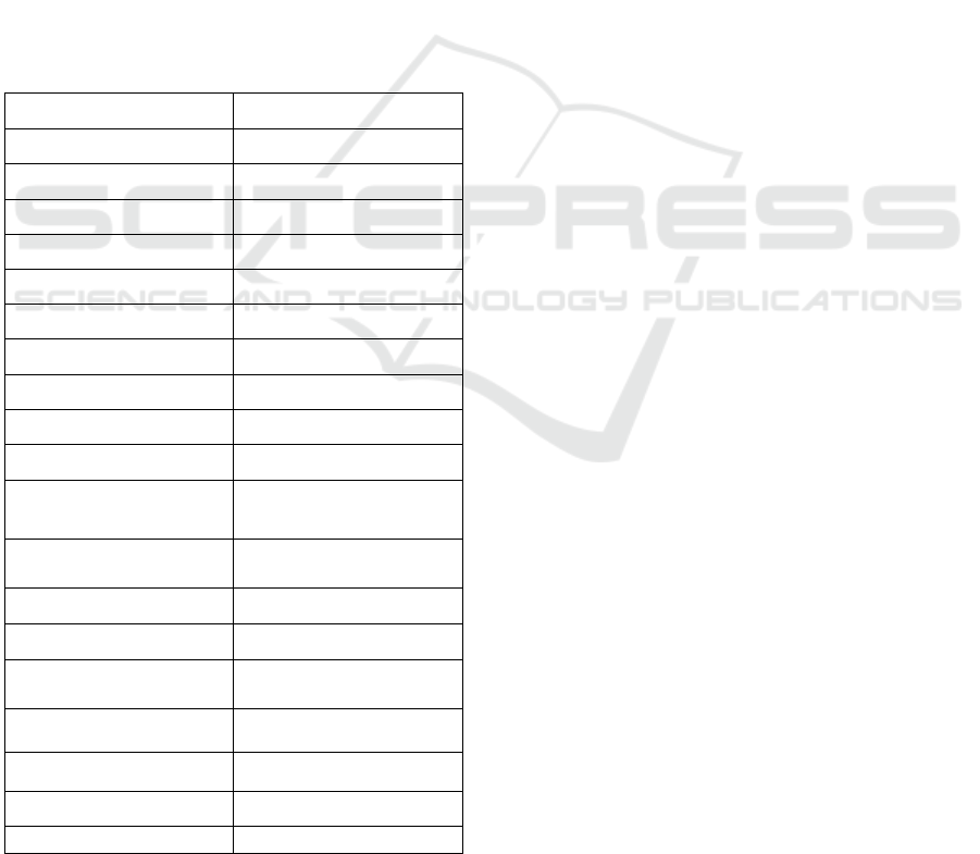
Table 1: Summary of Geometry Specifications.
PARAMETER
VALUE
Stator outer diameter
150mm
Stator inner diameter
100mm
Stator height
50mm
Rotor outer diameter
100mm
Rotor inner diameter
50mm
Rotor height
50mm
Air gap
1mm
Tooth Width
5mm
Tooth height
20mm
Slot depth
10mm
Phase resistance
0.96Ω
Aligned inductance
120 mH
Unaligned inductance
1204 mH
Phase current
8amps
Maximum phase
voltage
400V
Torque inertia
0.053 kg.m
2
Damping coefficient
0.008 nms
Maximum speed
1500 rpm
Power
5.5 Hp 4.1 kw
This geometric outline provides a solid foundation for
designing and building the switched reluctance motor,
ensuring optimal performance and efficiency based on
the specified operational parameters.
3 SIMULATION PROCEDURE
The proposed system aims to design an energy-
efficient Switched Reluctance Motor (SRM) utilizing
advanced simulation capabilities offered by ANSYS
software. The design process will encompass several
key stages, beginning with the selection of optimal
rotor and stator geometries to enhance torque density
and efficiency. By employing finite element analysis
(FEA), we will simulate the electromagnetic
performance, focusing on minimizing losses
associated with magnetic hysteresis and eddy
currents. The system includes the following features:
1. Geometric Optimization: Iterative design
adjustments to rotor and stator configurations to
achieve the best performance metrics.
2. Electromagnetic Analysis: Comprehensive
simulations to evaluate the motor’s magnetic
field distribution and torque characteristics
under various operating conditions.
3. Thermal Management: Assessment of thermal
behavior through heat dissipation analysis,
ensuring reliable operation and longevity of the
motor.
4. Performance Validation: Comparison of
simulation results with experimental data to
validate the design’s efficiency and
effectiveness.
By integrating these elements, the proposed
system aims to produce a high-performance SRM that
meets the growing demands for energy efficiency
while addressing the challenges faced by traditional
motor designs. This innovative approach is expected
to lead to significant advancements in motor
technology.
3.1 Motor Design Procedure
These steps can be used to design a motor in ANSYS.
It is explained using the following flowchart shown
in Figure 1.
This method makes use of ANSYS Maxwell,
which is especially well-suited for motor design and
electromagnetic field simulation.
Define the project in step 1.
Create a new project in ANSYS Maxwell.
Depending on your motor design requirements, select
between the 2D or 3D model. More complex
ISPES 2024 - International Conference on Intelligent and Sustainable Power and Energy Systems
42
geometries require 3D design, while most motors are
often developed in 2D.
To set up the workspace for motor design, choose
the "Electromagnetic" or "Motor template”. Establish
the Design Environment
Step 2: Specify the unit of measurement is mm
cm, inches etc.
Select each motor component's material from the
ANSYS library, or import your own if necessary. Set
up any extra parameters, like temperature, if thermal
analysis
Create the motor geometry in Step 3.
Draw your motor's fundamental geometry using
the sketch tools, beginning with the stator, rotor, and
slots.
For simpler modifications, parameterize important
dimensions (such as the slot geometry, rotor diameter,
and stator inner and outer diameters).
Make sure the components are properly aligned
and spaced apart.
Assign Material Properties in Step 4.
Assign materials to each component of the motor,
such as copper for the windings and steel for the stator
and rotor.
Use characteristics such as conductivity and
magnetic permeability, which are essential for precise
electromagnetic analysis.
Step 5: Establish Boundary Conditions and
Excitations. Define the stator's coil windings and
configure voltage or current excitations as necessary.
Set boundary constraints such as "Periodic" or
"Symmetry" to streamline the model and cut down on
computation.
Configure the simulation setup in Step 6.
Figure 1: Motor design in Ansys.
Configure the type of solver. Because it takes
time-dependent magnetic fields into account, the
Transient Magnetic Solver is frequently used for
motor design.
Establish the rotor's motion parameters, such as its
starting position and rotating speed.
Mesh the model in step 7.
To guarantee fine meshing in crucial regions,
particularly close to the air gap between the stator and
rotor, use automatic or manual meshing.
Verify the mesh quality because a finer mesh
produces more accurate results but requires more
computing time.
Step 8: Execute the Simulation
Launch the simulation and track its development.
Design of SRM
Determination of initial
Geometry
Selection of material
Analysis of the
electromagnetic
Post processing to calculate
static characteristics of the
machine
Static requirement
Winding configuration and
control strategy
Dynamic performance of the
SRM
Dynamic requirement
End
Design of Energy-Efficient Switched Reluctance Motor Using ANSYS Software
43
After the simulation is finished, look for any faults or
warnings in the solution configuration.
Step 9: Examine the Outcomes
To comprehend the electromagnetic behaviour, go
over vector plots, flux lines, and magnetic field
distributions.
To assess motor performance and efficiency, measure
torque, back-EMF, core losses, and other
performance metrics.
Modify the design parameters and execute the
simulation again if the motor does not satisfy
performance requirements.
Step 10: Design Optimization (Optional)
Automate parameter sweeps with ANSYS's
optimization tools to increase torque or motor
efficiency.
Establish goals and limitations for the design, then
allow the software to suggest the best changes.
Step 11: Complete the Model
Complete the motor design if the results are
satisfactory.
Export the simulation results, mesh, and geometry for
use in physical prototyping or additional analysis.
This procedure ought to provide ANSYS motor
design a solid basis.
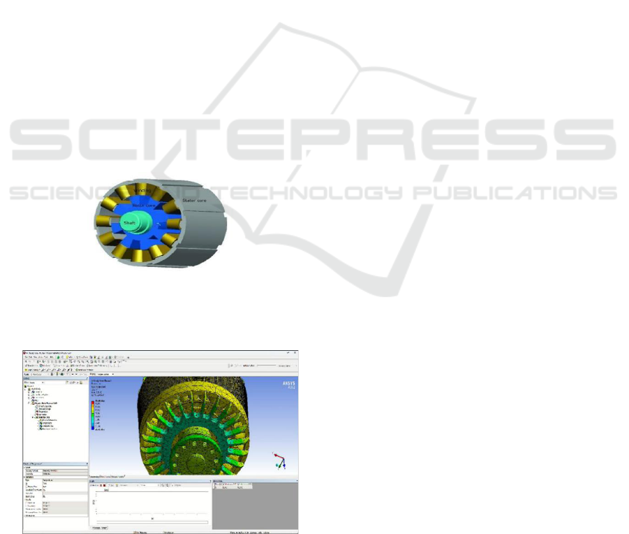
3.2 Motor Structure
The motor designed in Ansys is shown in Figure 2.
Figure 2: Motor structure.
3.3 Results and Discussion
Figure 3: Mesh distribution.
The finite element analysis and mesh
distribution is shown in Figure 3.
The simulation process typically involves
creating a detailed geometric model of the motor,
defining material properties, and setting up boundary
conditions. Using ANSYS Maxwell, engineers can
perform electromagnetic analysis to visualize flux
distributions and predict performance metrics such as
torque ripple and efficiency
By integrating these analyses, users can optimize
the design of SRMs for specific applications,
balancing factors like cost, performance, and
reliability. The ability to simulate various operating
conditions also aids in troubleshooting and improving
existing motor designs.
With an emphasis on crucial parameters including
magnetic flux density, torque output, back-EMF,
losses, and efficiency, the motor simulation in
ANSYS Maxwell offered a thorough examination of
the electromagnetic and thermal performance. The
main conclusions are summarized as follows:
Performance of Electromagnetics:
Magnetic Flux Density: To prevent saturation and
guarantee effective magnetic coupling, the flux
distribution in the stator and rotor stays within the
core material limits. On the other hand, minor
fluctuations close to the stator poles point to possible
regions for flux uniformity optimization.
Torque Output: The motor operates smoothly by
achieving a maximum torque within the design
parameters with little torque ripple. Any slight torque
ripple that is seen falls within the application's
permitted bounds.
Back-EMF: By matching the intended speed and
control parameters, the back-EMF profile verifies that
the motor will operate effectively under the intended
conditions.
Losses and Efficiency:
Core and Copper Losses: Core losses remain
moderate, attributed to optimized material selection
and design geometry. Copper losses are controlled,
though minor adjustments in winding resistance may
further reduce these losses.
Efficiency: The motor achieves a high efficiency
rate, indicating a well-balanced design with minimal
energy loss. This efficiency aligns with project
specifications and sustainable operation goals.
Temperature Distribution: The temperature
profile indicates a few hotspots near the windings, but
they are manageable within the designed cooling
system. Ensuring robust cooling or adjusting winding
material may further enhance thermal stability.
Structural Integrity: Force density analysis shows
the rotor and stator are structurally sound under
expected loads, confirming mechanical stability and
durability.
ISPES 2024 - International Conference on Intelligent and Sustainable Power and Energy Systems
44

4 CONCLUSIONS
In this paper, the design and simulation of an energy-
efficient Switched Reluctance Motor using ANSYS
demonstrate significant improvements in
performance. ANSYS provided valuable insights into
the motor's magnetic characteristics and efficiency
through detailed FEA, while MATLAB allowed for
the validation of the motor’s dynamic behavior under
real-world conditions.
The findings indicate that with optimized design
parameters, the SRM can achieve high torque with
low energy losses. The control strategies developed
enhance the efficiency further, making SRMs a viable
option for various applications, including electric
vehicles and industrial drives. Future work could
involve refining the design based on experimental
data and exploring advanced control algorithms for
improved performance.
REFERENCES
Ramamurthy, S.S., Balda, J.C., (2020). Sizing a switched
reluctance motor for electric vehicles. IEEE
Transactions on Industrial Electronics, 37(1), pp. 45–
54.
Kjaer, P.C., Gribble, J., Miller, T.J.E., (2021). High-grade
control of switched reluctance machines. IEEE
Transactions on Industrial Electronics, 33(11), pp.
1585–1593.
Choi, C., Kim, S., Kim, Y., Park, K., (2022). A new torque
control method of a switched reluctance motor using a
torque-sharing function. IEEE Transactions on
Magnetics, 38(51), pp. 3288–3290.
Russa, K., Husain, I., Elbuluk, M.E., (2022). Torque ripple
minimization in switched reluctance machines over a
wide speed range. IEEE Transactions on Industry
Applications, 34(5), pp. 1105–1112.
Ding, W., Fu, H., Hu, Y., (2018). Characteristics
assessment and comparative study of a segmented-
stator permanent-magnet hybrid-excitation SRM drive
with high-torque capability. IEEE Transactions on
Industrial Electronics, 33(1), pp. 482–500.
Callegaro, A.D., Bilgin, B., Emadi, A., (2019). Radial force
shaping for acoustic noise reduction in switched
reluctance machines. IEEE Transactions on Power
Electronics, 34(10), pp. 9866–9878.
Li, H., Bilgin, B., Emadi, A., (2019). An improved torque
sharing function for torque ripple reduction in switched
reluctance machines. IEEE Transactions on Power
Electronics, 34(2), pp. 1635–1644.
Ge, L., Xu, H., Guo, Z., Song, S., De Doncker, R.W.,
(2021). An optimization-based initial position
estimation method for switched reluctance machines.
IEEE Transactions on Power Electronics, 36(11), pp.
13285–13292.
Design of Energy-Efficient Switched Reluctance Motor Using ANSYS Software
45
