
Research on the Stress Analysis and Applicability of Flexible Support
Steel Strip in Soft Ground Highway Tunnels
Shiheng Yang
1,* a
, Tingwei Yang
1,2,3 b
, Chaobo Lu
1,2,3 c
and Chunfa Xiong
1,2,3 d
1
Guangxi Transportation Science and Technology Group Co., Ltd., Nanning 530007, Guangxi, China
2
Guangxi Highway Tunnel Safety Warning Engineering Research Center, Nanning 530007, Guangxi, China
3
Guangxi Key Lab of Road Structure and Materials, Nanning 530007, Guangxi, China
*
Keywords: Flexible Support Structure, Soft Ground, Highway Tunnel, Applicability Analysis.
Abstract: By using numerical experimental models, the support characteristics of steel arch bolt shotcrete initial
support structure and W-shape steel strip bolt shotcrete initial support system in grade IV surrounding rock
of soft ground highway tunnels were compared and analyzed. Experimental sections were carried out in
grade IV weak surrounding rock to compare the support effects of W-shape steel strip bolt shotcrete support
structure and steel arch bolt shotcrete support structure in soft ground highway tunnels. The results showed
that the use of W-shape steel strip bolt shotcrete support structure has the same good support effect as steel
arch bolt shotcrete support structure in soft ground highway tunnels. The implementation of W-shape steel
strip bolt shotcrete support structure can better exert the self-supporting capacity of surrounding rock, but its
restrained deformation amplitude is weaker than that of steel arch, which can provide reference for the
selection of support structure types for highway tunnels with similar geology.
a
https://orcid.org/0009-0009-9743-7885
b
https://orcid.org/0009-0004-4537-0205
c
https://orcid.org/0009-0003-8073-7714
d
https://orcid.org/0009-0005-7409-741X
1 INSTRUCTION
In the process of tunnel construction, the
surrounding rock and supporting structure interact
and deform together. During the deformation process,
the energy released by the surrounding rock, i.e. the
energy absorbed by the supporting structure, follows
the principle of energy conservation (Wang et al.,
2021). In the special environment of soft ground,
flexible support treatment should be carried out in
tunnel support, and the supporting structure can
undergo appropriate deformation, thereby enabling
the tunnel surrounding rock to fully exert its self
stabilization ability (Wei et al., 2017).
The flexible supporting system composed of
W-shape steel strip support, rockbolt, and anchor
cables combines the rockbolt and steel strips as the
main supporting structure under common force.
With flexible steel strips, the initial support structure
has better overall deformation coordination and
control ability, and is widely used in coal mine soft
rock roadway support (Sun, 2023; Sun, 2022; Zhang
and He, 2016).
The steel strip, due to its connection with the
anchor rod, can tightly adhere to the surface of the
surrounding rock, effectively preventing the collapse
of fragmented rock blocks when the tunnel arch or
side wall is relatively broken.Combining the radial
force provided by the rockbolt, a three-dimensional
control system is formed, which can fully utilize the
anchoring and suspension effects of the anchor cable
to reinforce the surrounding rock, enhance the
overall compressive strength of the surrounding rock,
increase the range of the surrounding rock
compressive stress zone, and prevent the overall
supporting structure of the rock from being damaged,
thereby controlling the displacement of the
surrounding rock and improving the overall stability
and bearing capacity of the tunnel (Lu et al., 2025;
Zhao et al., 2022; Zhang, 2014; Li et al., 2023).
Yang, S., Yang, T., Lu, C., Xiong and C.
Research on the Stress Analysis and Applicability of Flexible Support Steel Strip in Soft Ground Highway Tunnels.
DOI: 10.5220/0013574300004671
In Proceedings of the 7th International Conference on Environmental Science and Civil Engineering (ICESCE 2024), pages 109-117
ISBN: 978-989-758-764-1; ISSN: 3051-701X
Copyright © 2025 by Paper published under CC license (CC BY-NC-ND 4.0)
109
This paper conducts numerical simulation
calculations using the finite difference method to
compare and analyze the support effects of
traditional support structure and the flexible support
system in grade IV surrounding rock of weak rock
highway tunnels. The applicability of the flexible
support system composed of steel strip-rockbolt in
weak rock highway tunnels is explored. At the same
time, the support effect is compared through on-site
practical application.
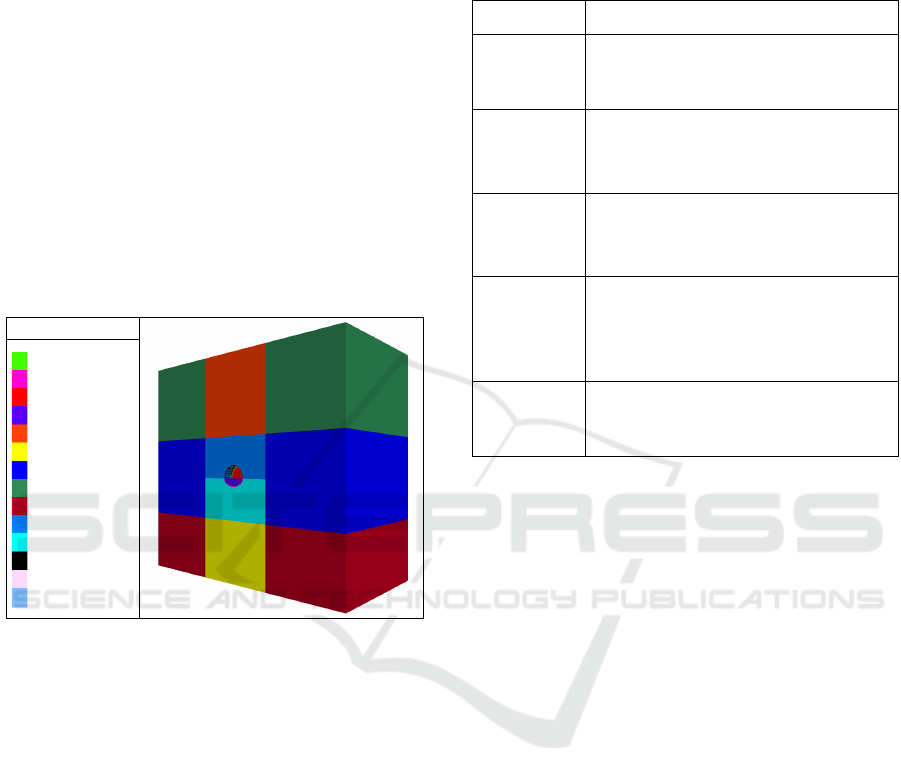
2 NUMERICAL EXPERIMENTAL
MODEL
The numerical experimental model is shown in
Figure 1.
Legen
d
concretlinersy
concretlinerxy
insiderocksy
insiderockxy
outsiderock
outsiderock2
outsiderock3
outsiderock4
outsiderock5
outsiderocksy
outsiderockxy
beamSEL
cableSEL
shellSEL
Figure 1: Numerical simulation calculation model.
The width of the tunnel in the numerical
experimental model is 12.46 m and the height is 9.7
m. The X and Z directions of the model area are
taken as 120 m and 110 m, respectively. The tunnel
depth is 60 m in the Y direction, with a burial depth
of 100 m. The longitudinal spacing between steel
strips or steel arch is 0.8 m, the longitudinal spacing
between rockbolt is 0.8 meters, and the
circumferential spacing is 1.2 meters, arranged in a
plum blossom shape. rockbolt are arranged at
different locations in two types of support structures.
In the initial support structure of steel arch bolt
shotcrete, they are arranged between two steel arch.
In the initial support structure of W-shape steel strip
bolt shotcrete, they are arranged at the center of each
steel strip. In numerical calculations, steel arch and
steel strips are simulated using Beam elements,
rockbolt are simulated using Cable elements, and
shotcrete is simulated using Shell elements
(Liu,
2023). The material parameters of different models
are shown in Table 1.
Table 1: Material parameter table for numerical model.
material parameter
surrounding
rock
Unit weight: 23 kN/m
3
; Elastic modulus:
3 GPa; Cohesion force: 0.3 MPa;
Friction angle: 44°; Poisson's ratio: 0.27.
shotcrete
Bulk modulus: 13 GPa; Shear modulus :
10 Gpa; Unit weight: 22.45 kN/m
3
;
Thickness: 22mm; Elastic modulus:
23GPa; Poisson's ratio: 0.2.
steel arch
Section area of I-beam No.16: 2610mm
2
;
Moment of inertia: 11300000mm
4
;
Elastic modulus: 210GPa; Poisson's ratio:
0.3.
W-shape
steel strip
Width: 300mm; Thickness: 4mm;
Cross-sectional area :810mm
2
;
Moment of inertia:40824mm
4
; Elastic
modulus: 210GPa; Moment of inertia:
0.3.
rockbolt
Diameter: 20mm, Elastic modulus:
210GPa; Poisson's ratio: 0.2.
3 ROCK EXCAVATION
DEFORMATION
Extract the deformation and stress conditions of two
types of support structures after construction, as well
as the stress conditions of the support components
for analysis. Among them, the steel support
components of traditional support structures and
flexible support structures are steel arches and steel
strips, respectively.
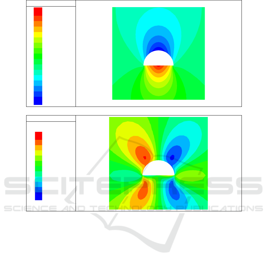
3.1 Rock Excavation Deformation
The displacement of the surrounding rock
deformation after tunnel excavation for the initial
support structure of steel arch bolt shotcrete and the
initial support structure of W-shape steel strip bolt
shotcrete is shown in Figure 2 and Figure 3.
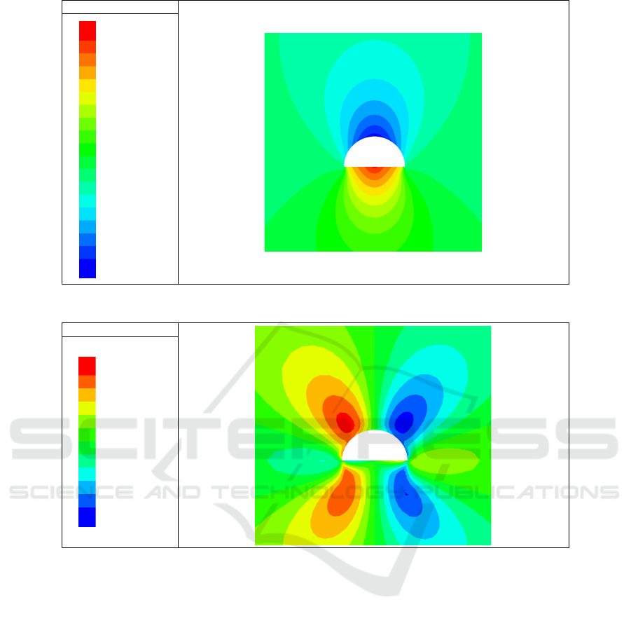
Due to the lower overall stiffness of the W-shape
steel strip compared to the steel arch, the
deformation of the surrounding rock will be slightly
greater when using the W-shape steel strip bolt
shotcrete support structure. However, the flexible
support structure also has a good effect on
controlling the surrounding rock of the tunnel.
ICESCE 2024 - The International Conference on Environmental Science and Civil Engineering
110
Displacement/mm
9.583
9.000
8.000
7.000
6.000
5.000
4.000
3.000
2.000
1.000
0.000
-1.000
-2.000
-3.000
-4.000
-5.000
-6.000
-6.826
(a)
Vertical displacement
Displacement/mm
1.011
1.000
0.800
0.600
0.400
0.200
0.000
-0.200
-0.400
-0.600
-0.800
-1.000
-1.024
(b) Horizontal Convergence
Figure 2: Deformation diagram of the initial support structure of steel arch bolt shotcrete.
3.2 Results of Plastic Zone of
Surrounding Rock
The distribution of plastic zones in the surrounding
rock after tunnel excavation under two different
working conditions is shown in Figure 4.
Different support structures are applied after
tunnel excavation, and the distribution of plastic
zones in the surrounding rock is basically the same,
mainly in the shear plastic zone. In terms of the size
of the plastic zone, the plastic zone of the
surrounding rock after flexible support structure is
applied is smaller than that of traditional support
structure, indicating that flexible support structure
can better exert the self-supporting capacity of the
surrounding rock.
3.3 Stress Characteristics of Rockbolt
The stress distribution of the rockbolt under two
working conditions after tunnel excavation is shown
in Figure 5.
Due to the influence of the joint support system
formed with the steel strip, the stress distribution of
the rockbolt in the flexible support structure is
different from that in the traditional support structure.
The axial force of the rockbolt reaches its maximum
value at the end of the rockbolt and gradually
decreases along the direction of the rockbolt.In
terms of overall force distribution, the rockbolt of
the two support structures are basically consistent,
both reaching their maximum values near the arch
springing. Among them, the rockbolt of the flexible
support structure receive a maximum axial force of
20kN, which is 1.4 times that of the traditional
support structure. This indicates that in the flexible
support
structure, the surface W-shape steel strip
Research on the Stress Analysis and Applicability of Flexible Support Steel Strip in Soft Ground Highway Tunnels
111
Displacement/mm
10.501
10.000
9.000
8.000
7.000
6.000
5.000
4.000
3.000
2.000
1.000
0.000
-1.000
-2.000
-3.000
-4.000
-5.000
-6.000
-7.000
-7.457
(a)
Vertical displacement
Displacement/mm
1.090
1.000
0.800
0.600
0.400
0.200
0.000
-0.200
-0.400
-0.600
-0.800
-1.000
-1.097
(b)
Horizontal Convergence
Figure 3: Deformation diagram of the initial support structure of W-shape steel strip bolt shotcrete.
yields pressure and exerts the tensile function of the
rockbolt.
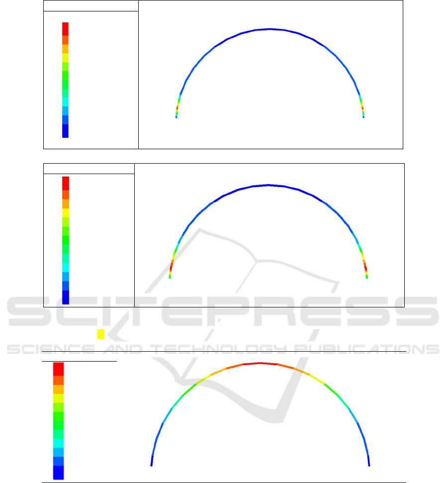
3.4 Stress Characteristics of Steel
Support
The bending moment distribution of the steel
support structure under two working conditions is
shown in Figure 6.
Compared with traditional support structures,
when constructing flexible support structures, the
bending moment experienced by steel strips is much
smaller than that of steel arches. The maximum
bending moment of the steel strip is 7.88 N·m, and
the maximum bending moment experienced by the
steel arch is 3.2 times that of the steel strip, with a
bending moment value of 25.26 N·m.
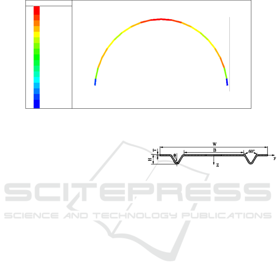
The stress distribution of the steel support
structure under two working conditions is shown in
Figure 7.
The stress distribution of the two support
structures is basically the same, with the arch crown
receiving the minimum stress and the arch lumbar
receiving the maximum stress. The maximum stress
value of the steel arch is 100.71 MPa, and the
maximum stress value of the steel strip is
126.78MPa. Compared with the steel arch, the joint
support structure formed by W-shape steel strip and
rockbolt is an active support structure, and the stress
distribution of the steel strip is more uniform.
ICESCE 2024 - The International Conference on Environmental Science and Civil Engineering
112
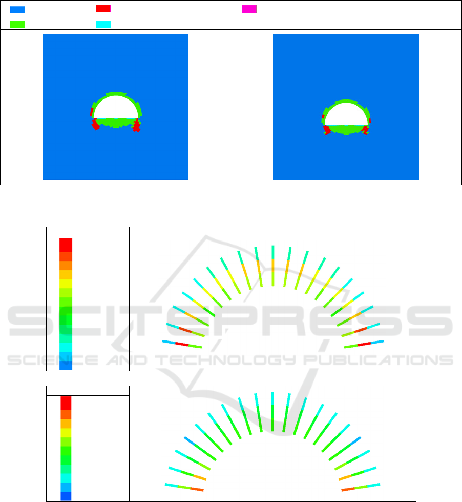
None shear-n shear-p shear-n shear-p tension-p
shear-p shear-p tension-p
(a)
support structure of steel arch (b)
support structure of W-shape steel strip
Figure 4: Distribution of plastic zone in surrounding rock of support structure.
Axial force/kN
14.65
14.00
13.00
12.00
11.00
1.00
9.00
8.00
7.00
6.00
5.00
4.00
3.00
2.00
(a)
support structure of steel arch
Axial force/kN
20.37
20.00
18.00
16.00
14.00
12.00
10.00
8.00
6.00
4.00
2.00
(b)
support structure of W-shape steel strip
Figure 5: Axial force diagram of anchor rods with different support structures.
Although the W-shape steel strip has a weaker
constraint on the excavation deformation of the
surrounding rock compared to the steel arch bolt
shotcrete support structure, and the stress amplitude
of the W-shape steel strip is also larger than that of
the steel arch, it is still within the yield strength.
Compared with the steel arch bolt shotcrete support
structure, through deformation, it can fully exert the
deep migration of the surrounding rock stress and
the self bearing capacity of the surrounding rock.
The steel strip is closely attached to the surface of
the surrounding rock and works together with
rockbolt to provide "active support" for the
surrounding rock, which could make the
effectiveness of the steel strip is higher than that of
the steel arch.
Research on the Stress Analysis and Applicability of Flexible Support Steel Strip in Soft Ground Highway Tunnels
113
Bending moment/(N·m)
25.26
25.00
22.50
20.00
17.50
15.00
12.50
10.00
7.50
5.00
2.50
0.00
-2.39
(a)
support structure of steel arch
Bending moment/(N·m)
7.88
7.00
6.00
5.00
4.00
3.00
2.00
1.00
0.00
-1.00
-2.00
-3.00
-4.00
-4.29
(b)
support structure of W-shape steel strip
Figure 6: Bending moment diagram of steel support for different support structures.
Axial stress/MPa
48.86
50.00
55.00
60.00
65.00
70.00
75.00
80.00
85.00
90.00
95.00
100.00
100.71
(a)
support structure of steel arch
ICESCE 2024 - The International Conference on Environmental Science and Civil Engineering
114
Axial stress/MPa
87.37
87.50
90.00
92.50
95.00
97.50
100.00
102.50
105.00
107.50
110.00
112.50
115.00
117.50
120.00
122.50
125.00
126.78
(b)
support structure of W-shape steel strip
Figure 7: Stress diagram of steel support for different support structures.
4 ENGINEERING APPLICATION
TESTS
4.1 Experimental Design
Based on a certain highway tunnel, a field test
section was conducted. The
ZK101+500-ZK101+650 tunnel is designed with
grade Ⅳ surrounding rock, with a tunnel burial
depth of 110m~133m. The formation is composed of
moderately weathered thin sandstone interbedded
with mudstone, with well-developed joints and
fissures, and the surrounding rock is relatively
fragmented. The original design adopted the grade
Ⅳa support method, with initial support parameters
of HRB400 grade 3 threaded steel; the diameter of
the rockbolt is 20mm, the type of it is mortar
rockbolt, the length of it is 3.0m; the diameter of the
steel mesh is 6.5mm, and the arrangement is
25×25cm; the steel arch adopts I16 I-beam with a
longitudinal spacing of 80cm; the shotcrete adopts
C20 strength and is applied with a thickness of 22cm;
the design requirement is to reserve a thickness of
8cm after excavation. The construction of this
section adopts the two-step method for excavation,
with a height of 4.5 meters for the excavation of the
upper center bench . After excavation, 13 steel strips
are continuously used instead of the original design
I16 I-beam steel arch at ZK101+560-ZK101+570.4.
The steel strip structure is shown in Figure 8.
W-steel strip width, 300mm; B-Steel strip support width,
155.6mm; H-steel strip height, 23.5mm; T-steel strip thickness,
4mm, Sectional area, 810mm
2
Figure 8: Structural diagram of experimental steel strip.
The middle position of the section ZK101+565 is
selected as the monitoring section, and compared
with the adjacent section ZK101+555 steel arch
support structure section. The experimental section
setting is shown in Figure 9.The actual installation
of steel support components on site is shown in
Figure 10.
4.2 Test Results
The deformation monitoring data of two sections for
40 days of support deformation monitoring are
shown in Figure 11.
By comparing the deformation of two
cross-sectional support structures, it was found that
under the same surrounding rock conditions, their
deformation patterns were basically the same. The
deformation increased rapidly in the first 7 days and
eventually stabilized over time.
In addition, no cracking or block shedding was
found in the on-site support structure. The initial
support structure composed of W-steel strips
replacing steel archs can also maintain the stability
of weak surrounding rock for the support of
excavated highway tunnels.
Research on the Stress Analysis and Applicability of Flexible Support Steel Strip in Soft Ground Highway Tunnels
115
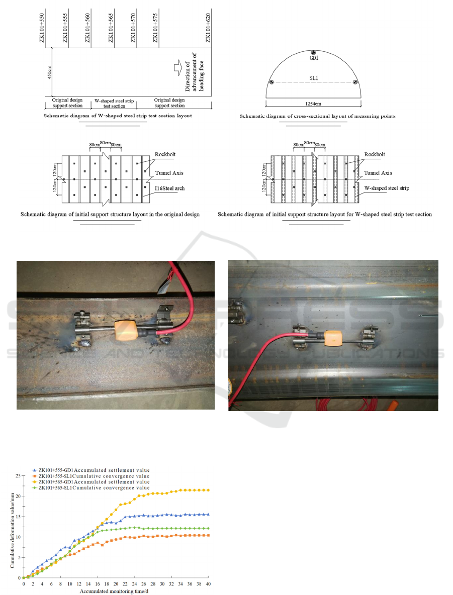
Figure 9: Schematic diagram of engineering test layout.
(a)
Rigid connection of sensors in steel arch (b)
Rigid connection of sensors in W-shape steel strip
Figure 10: Layout of engineering test site.
Figure 11: Monitoring section deformation curve.
5 CONCLUSION
By establishing a numerical model, a stress analysis
was conducted on the flexible support structure
constructed in soft ground highway tunnels. The
feasibility of using steel strips instead of traditional
steel arches was compared and verified through field
experiments, and the following conclusions were
drawn.
(1) In soft ground, the initial support structure
composed of W-steel strips replacing steel arch has
basically the same support effect on the excavated
highway tunnel, but the constraint amplitude for
ICESCE 2024 - The International Conference on Environmental Science and Civil Engineering
116

tunnel excavation deformation control of steel strip
is smaller than that of steel archs.
(2) Compared with the initial support structure
composed of steel arch, the range of damage or yield
in the plastic zone of the surrounding rock caused by
the initial support structure of W-steel strip is
basically the same. The initial support structure of
W-steel strip can better exert the self-supporting
capacity of the surrounding rock.
(3) Within the safe strength range, the initial
support structure of W-steel strip can better utilize
the strength advantages of steel materials and
rockbolt, and fully exert its support effect.
(4) Through on-site testing, it has been verified
that the initial support structure composed of
W-steel strips replacing steel arch can also maintain
the stability of weak surrounding rock for the
support of excavated highway tunnels.
DECLARATION OF COMPETING
INTEREST
The authors declare that they have no known
competing financial interests or personal
relationships that could have appeared to influence
the work reported in this paper.
ACKNOWLEDGEMENTS
The research of this article is supported by
Guangxi's key research and development plan
(Guike AB24010276).
REFERENCES
Wang, W., et al. 2021. Mechanical Analysis of
Non-circular Tunnel Lining Considering
Ground-support Interaction. Chinese Journal of
Underground Space and Engineering, 17(S2):
631-636+649.
Wei, Z., He, F., Zhang, G., et al. 2017. Failure
mechanism and cable truss control of large-scale
section gob-side entry roof with fully mechanized
caving. Journal of Mining & Safety Engineering,
34(1): 1-8.
Sun, H. 2023. Interaction and Stability Analysis of
Surrounding Rock and Lining Structure of High
Temperature Hydraulic Tunnel. Shihezi University,
Shihezi.
Sun, H. 2022. Research on the large deformation
mechanism of soft rock and support
countermeasures of NPR anchor cable-truss in Tayi
tunnel. China University of Mining &
Technology-Beijing, Beijing.
Zhang, G., He, F. 2016. Asymmetric failure and control
measures of large cross-section entry roof with
strong mining disturbance and fully-mechanized
caving mining. Chinese Journal of Rock Mechanics
and Engineering, 35(4): 806-818.
Lu, W., et al. 2025. Study on the mechanism of roof
collapse and anchoring-grouting support parametric
sensitivity in deep goaf based on upper limit
method. Journal of Mining & Safety Engineering,
1-16.
Zhao, Z., Yang, P., Zhang, M., et al. 2022. Stability of
weakly cemented soft surrounding rock under
combined effect of water environment and
inhomogeneous ground stress. Journal of Mining &
Safety Engineering, 39(1): 126-135.
Zhang, J. 2014. Engineering Geological Properties of
Soft Surrounding R ocks of Mountain-crossing
Tunnels and Construction Countermeasures. Tunnel
Construction, 34(08): 749-753.
Li, J., et al. 2023. Study on Structural Effect of Steel
Belt of Prestressed Anchorage System for Soft Rock
Tunnel. Journal of Disaster Prevention and
Mitigation Engineering, 43(01): 41-49.
Liu, F. 2023. Treatment of Highway Tunnel Disease and
Finite Element Analysis of Steel Belt
Reinforcement Technology. Construction& Design
For Project, (01): 96-98.
Research on the Stress Analysis and Applicability of Flexible Support Steel Strip in Soft Ground Highway Tunnels
117
