
Structure Design of Jointless Cement Concrete Pavement
Zhihua Niu
1a
and Xiaoyu Liu
2,* b
1
PowerChina Northwest Engineering Corporation Limited, No.18 Zhangba Road, Yanta District, Xi’an 710065, China
2
School of Civil Engineering, Xi’an University of Architecture and Technology, No. 13 Yanta Road, Beilin District,
Xi’an 710055, China
*
Keywords: Jointless Cement Concrete Pavement, Structure Design, ECC, Finite Element Model, Stress Analysis.
Abstract: Joints in cement concrete pavements frequently contribute to decreased ride quality, accelerated pavement
deterioration, and complex maintenance procedures. To mitigate these issues, this study proposes the use of
engineered cementitious composites (ECC) as connectors at pavement joints, creating a jointless cement
concrete pavement (JCCP) system. A finite element model was developed to evaluate the structural
performance of JCCP, taking into account variables such as vehicle loading, width and thickness of ECC
connector dimensions. The mechanical behavior of the JCCP under combined loading and temperature-
induced stresses was analyzed, and the critical load position was identified. The results reveal that the most
critical load position occurs directly above the induced crack in the pavement. The integration of ECC
connecting elements reduced the maximum tensile stress at the base of the pavement by nearly 50%. Based
on these findings, it is recommended to utilize ECC connectors with a width of 30 cm, and a thickness equal
to 50% of the pavement slab’s thickness.
1 INTRODUCTION
Compared to asphalt pavements, cement concrete
pavements have several advantages, including lower
construction costs, higher stiffness, longer service
life, and better stability (Plati 2019). However, the
application of cement concrete pavements in high-
class highways has been declining due to the negative
impacts of joints, such as poor ride quality, increased
susceptibility to pavement distresses, and difficult
maintenance. To address these limitations,
optimizing the joint design of cement concrete
pavements, reducing the number of joints, and even
achieving jointless constructions can significantly
improve pavement performance and promote the
wider adoption of cement concrete pavements in
high-class highways.
To mitigate cracking induced by temperature and
shrinkage stresses in concrete pavements, equally
spaced transverse and longitudinal joints are typically
constructed to accommodate these stresses (Das et al.,
2020). Joints are critical components of concrete
a
https://orcid.org/0009-0000-9338-1508
b
https://orcid.org/0009-0004-5745-0341
pavements but are also the weakest points, prone to
failures such as slab pumping, faulting, and spalling.
Existing research has demonstrated that the majority
of distress in concrete pavements is concentrated
around joint edges, particularly at the corners where
transverse and longitudinal joints intersect. Existing
measures to mitigate the adverse effects of joints
primarily involve regular cleaning and maintenance
of the pavement surface and joints, especially during
the early stages of service life. However, these
measures can only delay the onset of joint-related
distress and do not fundamentally eliminate the
negative impacts of joints.
Engineered Cementitious Composites (ECC)
exhibit exceptional ductility and toughness, with
ultimate tensile strains reaching 3-8%, which is 300-
800 times that of ordinary concrete (Li 1993). This
superior deformability makes ECC an excellent
candidate for accommodating deformations in
concrete pavements induced by temperature
variations (Arce et al., 2021). Moreover, ECC
possesses outstanding crack control capabilities,
dispersing single cracks in ordinary concrete into
102
Niu, Z., Liu and X.
Structure Design of Jointless Cement Concrete Pavement.
DOI: 10.5220/0013574200004671
In Proceedings of the 7th International Conference on Environmental Science and Civil Engineering (ICESCE 2024), pages 102-108
ISBN: 978-989-758-764-1; ISSN: 3051-701X
Copyright © 2025 by Paper published under CC license (CC BY-NC-ND 4.0)

multiple microcracks with widths less than 100 μm,
and exhibiting self-healing properties (Shi et al.,
2017). The ultra-high toughness, high tensile strain
capacity, and superior crack resistance of ECC enable
it to absorb the deformations caused by thermal
stresses in concrete pavements (Singh et al., 2019) By
undergoing tensile and compressive deformations,
ECC can accommodate structural deformations
resulting from temperature changes. Additionally,
the exceptional ductility and multiple cracking
characteristics of ECC effectively inhibit and delay
the initiation and propagation of cracks in concrete
pavements, thereby prolonging the service life of the
entire pavement structure (Ismail et al., 2018). Zhang
et al. (Zhang et al., 2017; Zhang et al., 2013) explored
the performance of jointless concrete pavements and
found that ECC could continue to transmit forces
even after cracking. Although a limited number of
studies have been conducted on the application of
ECC in jointless concrete pavements in China (Cao
2021), specific structural design parameters for ECC
have not been clearly established, and corresponding
design methods are lacking. This paper develops a
finite element model of a jointless concrete pavement
structure, considering the effects of loading and
temperature stresses, to investigate and analyze the
mechanical response of the pavement structure under
various ECC connecting segment widths and
thicknesses. The objective is to determine the optimal
design parameters for ECC connecting segments in
jointless concrete pavements and to optimize the
design of jointless concrete pavement structures.
2 PAVEMENT STRUCTURE AND
MATERIALS
This paper establishes two types of pavement
structures: jointed plain concrete pavement (JPCP)
and jointless cement concrete pavement (JCCP).
Appropriate pavement materials were selected, and
ECC were prepared for use in the corresponding
pavement structures.
2.1 JPCP
As shown in Figure 1(a), the JPCP structure consists
of a subgrade, a base course, and a surface course. As
illustrated in Figure 1(b), the surface course is
composed of nine 5 m×4 m×0.28 m concrete slabs
joined together with a 6 mm joint spacing. The base
course consists of a 0.36 m thick cement-stabilized
base layer.
(a) Pavement structure diagram
(b) Plan view of pavement structure
Figure 1: JPCP structure.
2.2 JCCP
As shown in Figure 2 (a), the JCCP structure is
developed based on the JPCP structure by replacing
the traditional joints with ECC transition zones. An
induced crack is set directly below the ECC transition
zone, with the transfer bar located at the middle of the
induced crack and the anchorage steel bars located at
the middle of the interface between the ECC
transition zone and the concrete slab. Figure 2 (b) is
a plan view of the JCCP structure, where both
transverse and longitudinal joints are replaced by
ECC transition zones.
(a) Pavement structure diagram
(b) Plan view of pavement structure
Figure 2: JCCP structure.
Structure Design of Jointless Cement Concrete Pavement
103
2.3 Pavement Materials
C50 concrete was selected as the cement concrete
surface layer material for both pavement structures,
while ECC material was prepared for the ECC
transition zone of the JCCP structure. The raw
materials for ECC included cement, fly ash, silica
sand, water reducer, and polyethylene (PE) fiber.
Four-point bending tests and elastic modulus tests
were conducted to determine the flexural strength of
C50 and ECC, which were found to be 5.1MPa and
20.0MPa, respectively. The elastic modulus of C50
and ECC were 36100MPa and 29800MPa,
respectively, and the subgrade reaction modulus was
60MN/m³. The pavement materials parameters are
shown in Table 1.
Table 1: Pavement material parameters.
Materi
als
Flex
ural
stren
gth
(
MPa
)
Elasti
c
modu
lus(
MPa
)
Poiss
on's
ratio
Dens
ity(
kg/m
³)
Thick
ness
(m
)
Concre
te
5.1
3610
0
0.15 2800 0.28
ECC
Transit
ion
zone
20.0
2980
0
0.15 2000 0.14
Cemen
t-
stabiliz
ed
b
ase
/ 1800 0.25 2200 0.36
Transf
er and
Tie bar
Ancho
rage
steel
b
a
r
/
2000
00
0.3 7850 /
Subgra
de
Reaction modulus: 60(MN/m³)
3 FINITE ELEMENT MODEL
ESTABLISHMENT AND
VERIFICATION
3.1 Establishment and Mechanical
Responses Analysis of Two
Pavement Models
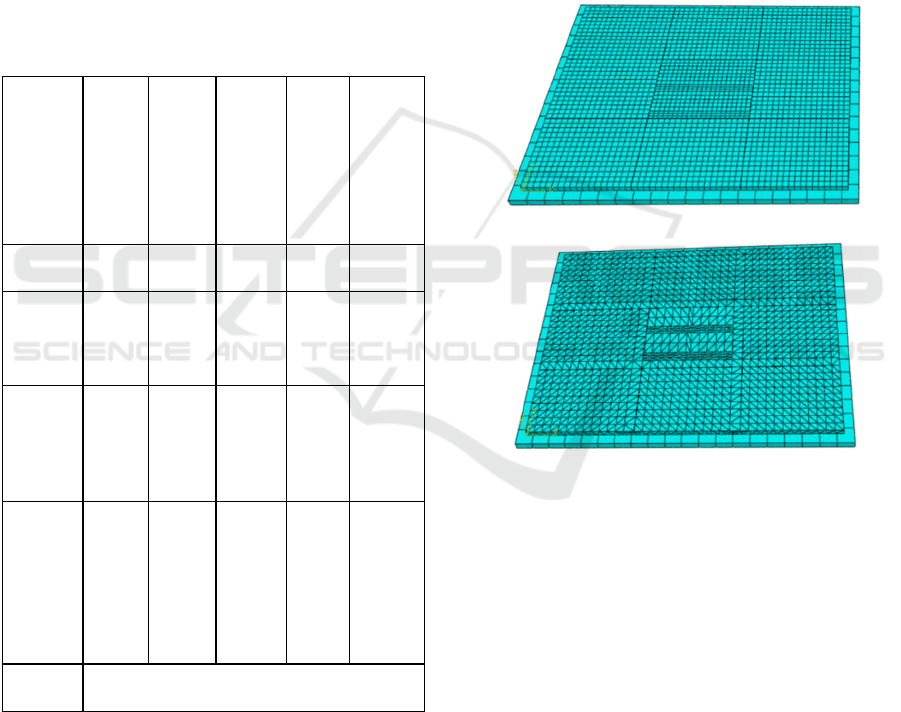
In this paper, two pavement structure models were
established using ABAQUS software to simulate and
analyze the mechanical response of the pavement
under load and temperature. As shown in Figures 3
(a) and (b), nine concrete slabs were set up in the
ABAQUS finite element model.
(a) Model of JPCP
(b) Model of JCCP
Figure 3: Finite element model of the pavement structure.
This study used a typical winter day in Xi’an with
a significant temperature gradient as a reference to
establish temperature field conditions for the two
pavement models (Wu 1992). The temperature field
was defined based on the temperature distribution at
various depths at the time of the lowest daily
temperature. Figure 4 illustrates the temperature
distribution at different depths at the moment of the
lowest daily temperature.
ICESCE 2024 - The International Conference on Environmental Science and Civil Engineering
104
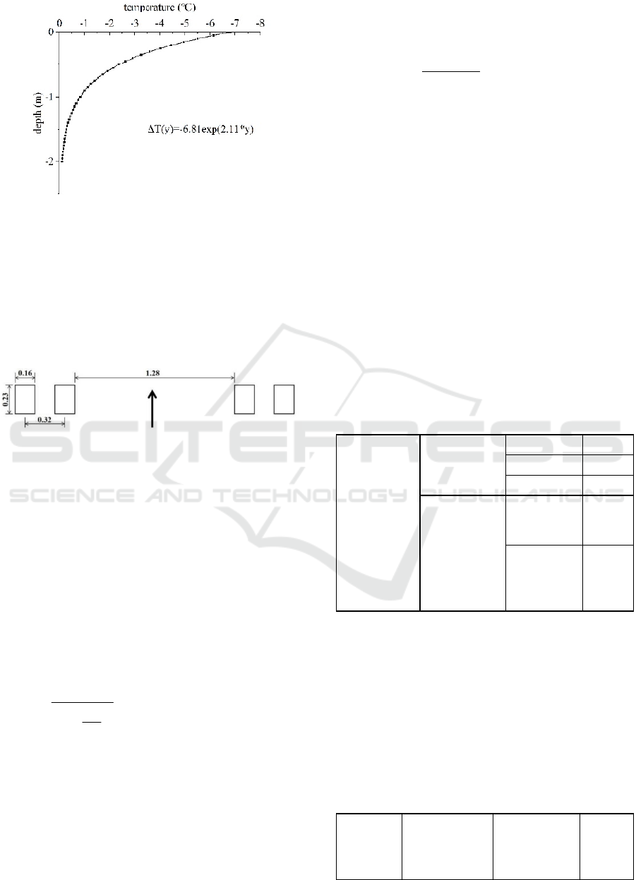
Figure 4: Minimum temperature at various depths in Xi’an.
In this study, a single-axle dual-wheel assembly
load was applied, with axle loads of 100kN, 150kN,
and 180kN, respectively. These axle loads were
converted into rectangular uniformly distributed
loads as shown in Figure 5. There were two wheels
on each side, with a center-to-center spacing of
0.32m. The contact area of the wheel load was
simplified as 0.23m × 0.16m.
Figure 5: Distribution of vehicle load on the pavement
(unit: m).
3.2 Stress Responses in JPCP
Based on the pavement structure and material
parameters in Section 2, the load stress and
temperature stress of ordinary Portland cement
concrete pavement are calculated. First, the stress in
the pavement slab under different axle loads was
calculated. Since the lower layer is made of cement-
stabilized gravel, there is no need to calculate its load
stress. Only the load stress of the upper cement slab
under the design load is calculated, which is obtained
from Equation 1:
3
0.65 2 0.94
pgc
b
c
1.45 10
rhP
D
1
D
−
−
×
σ=
+
(1)
where
p
σ is the stress due to load,
b
D
is the flexural
rigidity of the lower plate,
c
D
is the flexural rigidity
of the upper plate,
g
r
is the total relative stiffness
radius of the two-layer plate,
c
h
is the flexural
thickness of the upper plate, and
P
is the design
load.
The maximum temperature stress in the concrete
pavement slab under the maximum temperature
gradient is calculated as shown in Equation 2:
cccg
t,max L
EhT
B
2
α
σ=
(2)
where
c
α
is the coefficient of linear thermal
expansion of concrete,
c
E
is the modulus of
elasticity of the upper plate,
g
T is the maximum
temperature gradient, and
L
B
is the temperature
stress coefficient considering both temperature
warping stress and internal stress.
Equation 3 gives the calculated temperature
fatigue stress at the critical load position of the
surface layer.
tr t t,max
kσ= σ
(3)
where
t
k
is defined as the temperature fatigue stress
coefficient.
The theoretical calculation results of load stress
and temperature stress for JPCP are presented in
Table 2.
Table 2: Theoretical calculation results of JPCP stress
response (Unit: MPa).
Theoretical
Calculation
Results of
JPCP Stress
Response
load stress
100kN 1.501
150kN 2.198
180kN 2.609
temperature
stress
thermal
fatigue
stress
0.306
maximum
thermal
warping
stress
1.101
3.3 Finite Element Model Verification
A comparison between the finite element simulation
results and theoretical calculation results of JPCP
under load stress is presented in Table 3. The
maximum error between the two is 6.48%. Therefore,
the finite element model established in this paper is
reasonable and feasible.
Table 3: Comparison of finite element simulation and
theoretical calculation results for JPCP.
Axle
load
Theoretical
calculated
value (MPa)
Finite
element
simulation
value (MPa)
Error
(%)
Structure Design of Jointless Cement Concrete Pavement
105

100kN 1.501 1.490 0.73
150kN 2.198 2.122 3.46
180kN 2.609 2.440 6.48
4 INFLUENCE OF STRUCTURAL
DESIGN PARAMETERS OF
ECC JOINTS ON
MECHANICAL RESPONSE
4.1 Determination of Critical Load
Position
The critical load position for JPCP is at the mid-span
of the longitudinal joint, according to the design
code. However, as a novel pavement structure, the
critical load position of JCCP needs to be determined.
In this study, a JCCP structure with an ECC joint
width of 50 cm and thickness of 14 cm is taken as an
example to analyze the stress response of JCCP under
loads applied at five different positions. The five load
positions are as follows: (a) load at the mid-span of
the long side of the concrete slab, as shown in Figure
6(a); (b) load at the corner of the concrete slab, as
shown in Figure 6(b); (c) load directly above the
induced crack, as shown in Figure 6(c); (d) load at the
mid-span of the ECC joint, as shown in Figure 6(d);
(e) load on both sides directly above the induced
crack, as shown in Figure 6(e).
(a) At mid-span of the
lon
g
side
(b) At the corner
(c) Directly above the
induced
j
oin
t
(d) At the mid-span of
the ECC
j
oin
t
(e) Both sides directl
y
above the induced crac
k
Figure 6: Different load positions.
The influence of different load positions on the
maximum tensile stress in each structural layer is
shown in Table 4 based on finite element simulation
results.
Table 4: Maximum tensile stress values in different load
positions. (unit: MPa).
Load
positions
Cement
concret
e slab
Base
course
EC
C
join
t
Re
bar
(a) At the
mid-span of
the long side
of the
concrete
slab
0.757 0.057
0.45
6
8.0
23
(b) At the
corner of the
concrete
slab
0.764 0.060
0.46
5
8.6
38
(c) Load
directly
above the
induced
crac
k
0.767 0.063
0.59
1
14.
811
(d) Load at
the mid-
span of the
ECC
j
oin
t
0.725 0.056
0.51
6
18.
210
(e) Load on
both sides
directly
above the
induced
crac
k
0.725 0.045
0.21
7
7.1
15
The maximum tensile stress at the bottom of the
JCCP surface layer is only about 50% of that of the
JPCP. Tensile stresses at the bottom of each layer
reach their maximum when the load is applied
directly above the center of the induced crack. The
maximum tensile stress at the bottom of the surface
ICESCE 2024 - The International Conference on Environmental Science and Civil Engineering
106

layer under this condition is 0.767MPa. Conversely,
the minimum tensile stresses in each layer occur
when the load is applied on both sides directly above
the induced crack. Therefore, the critical load
position of the JCCP is determined to be directly
above the center of the induced crack.
4.2 Determination of Width of ECC
Joint
To investigate the influence of ECC joint width on
the stress response of JCCP, the ECC joint widths
were varied as 5cm, 10cm, 15cm, 20cm, 30cm, 40cm,
50cm, and 60cm. The upper width of the ordinary
concrete section varied accordingly, while the lower
part remained constant at 5m×4m. The thickness of
the ECC joint was still half of the surface slab. Figure
7 shows the variation of maximum tensile stress at
the bottom of the slab for different ECC joint widths.
Figure 7: Influence of ECC joint width on maximum tensile
stress at the slab bottom.
As shown in Figure 7, the maximum tensile stress
at the bottom of the slab initially decreases and then
increases with the increase of ECC joint width. The
minimum value of 0.737MPa is obtained when the
width is 15cm. When the ECC joint width is 40cm,
the maximum tensile stress at the bottom of the slab
increases abnormally, which is because the first
wheel on the left side of the single-axle dual-wheel
load in the driving direction acts entirely on the ECC
joint at this time, but its stress is 0.825MPa, which is
still less than that of JPCP.
In addition, concrete slabs are subjected to
temperature and shrinkage deformations. To prevent
cracking, joints are usually required in JPCP. For
JCCP, ECC has excellent ductility and deformability.
It is required that the ECC joint at the joint position
can absorb the tensile strain caused by temperature
and shrinkage deformation of the slab. Therefore,
when determining the width of the ECC joint, it is
necessary to ensure that the ultimate tensile strain of
ECC is not less than the required value of the overall
tensile strain of the slab. The required value of the
overall tensile strain of the slab can be calculated
theoretically and is related to temperature and
concrete shrinkage deformation, as shown in
Equation 4.
RT sh
Tε=αΔ+ε
(4)
where
R
ε
is the required tensile strain of the entire
pavement slab,
T
α
is the thermal expansion
coefficient of concrete, typically taken as 0.001%/°C,
TΔ
is the annual temperature difference (about 40°C
in Xi'an), and
sh
ε
is the concrete shrinkage strain,
typically 0.06%. The calculated value of
R
ε
is
0.10%.
The overall strain capacity of the pavement slab
in the longitudinal direction under uniaxial tension is
given by Equation 5.
c
LL
LL
ε=ε +ε
ⅠⅡ
ⅠⅡ
(5)
where
ε
Ⅰ
is the ultimate tensile strain of ECC,
ε
Ⅱ
is
the strain of concrete under the corresponding axial
tensile load,
L
is the length of the pavement slab,
and
LandL
ⅠⅡ
are the lengths of the ECC and
concrete sections, respectively.
Both the ultimate tensile strain and width of the
ECC joint can enhance the overall deformation
capacity of the slab. For a 5m long slab, a
conservative value of 1.5% is adopted for the ultimate
tensile strain of the ECC joint, while the strain of
concrete under corresponding axial tensile load is
obtained from experiments and is taken as 0.01% in
this case. Substituting the required strain value
obtained from the above equation into the overall
deformation capacity, we finally obtain:
L 268.46mm L 4731.54mm==
ⅠⅡ
、
.Considering
the calculation results and a certain safety factor, as
well as construction convenience, the width of the
ECC joint for a 5.0m long slab is determined to be
300mm.
4.3 Determination of Thickness of
ECC Joint
To investigate the influence of ECC joint thickness
on the stress response of JCCP, the ECC joint
thickness was varied as 25%, 40%, 50%, 60%, and
75% of the pavement slab thickness. Figure 8
illustrates the variation of maximum tensile stress at
Structure Design of Jointless Cement Concrete Pavement
107

the bottom of the slab for different ECC joint
thicknesses.
Figure 8: Influence of ECC joint thickness on maximum
tensile stress at the slab bottom.
As shown in the Figure 8, the maximum tensile
stress at the bottom of the slab decreases with the
increase in the thickness ratio of the ECC joint. After
the thickness ratio reaches 50%, the change in the
maximum tensile stress at the bottom of the slab
becomes insignificant. The selection of ECC joint
thickness should also consider the diameter of the
anchor bars, force transfer bars, and tension bars, as
well as the concrete cover thickness. For the JCCP
structure proposed in this paper, it is recommended to
select an ECC joint thickness ratio of 50%.
5 CONCLUSIONS
In this study, a jointless concrete pavement with an
engineered cementitious composite (JCCP) was
designed, and a finite element model of the JCCP
structure was established. Considering the effects of
load stress and temperature stress, the influence of
vehicle load, ECC joint width, and thickness on the
mechanical response of JCCP was investigated and
analyzed, and the JCCP structure was optimized.
(1) Compared with JPCP, the maximum tensile
stress at the bottom of the JCCP surface layer is
only about 50% of that of JPCP, indicating that
JCCP can effectively reduce the stress in the
concrete slab.
(2) By comparing the stress responses of JCCP
under different load positions, it was
determined that the critical load position of
JCCP is the middle of the slab directly above the
induced crack.
(3) For the JCCP structure proposed in this paper, it
is recommended that the width of the ECC joint
be 30 cm, and the thickness be 50% of the
pavement slab thickness.
ACKNOWLEDGMENTS
This research was funded by Scientific Research
Program Funded by Education Department of
Shaanxi Provincial Government (Program
No.23JC046)
REFERENCES
Plati, C., 2019. Sustainability factors in pavement
materials, design, and preservation strategies: A
literature review. Construction and Building Materials
211, 539-555.
Das, A., Bhuyan, M.R., Khattak, M.J., Zhang, Q., 2020.
Mitigating reflective cracking in composite
pavements through the use of a ductile concrete
interlayer. Construction and Building Materials, 259,
120383.
Li, V.C., Stang, H., Krenchel, H., 1993. Micromechanics
of crack bridging in fibre-reinforced concrete.
Materials and Structures, 26, 486-494.
Arce, G.A., Noorvand, H., Hassan, M.M., Rupnow, T.,
Dhakal, N., 2021. Feasibility of low fiber content PVA-
ECC for jointless pavement application. Composites:
Part B, 50, 224-231.
Shi, T., Leung, C.K.Y., 2017. An effective discrete model
for strain hardening cementitious composites: Model
and concept. Computers and Structures, 185, 27-46.
Singh, M., Saini, B., Chalak, H.D., 2019. Performance and
composition analysis of engineered cementitious
composite (ECC) – A review. Journal of Building
Engineering, 26, 100851.
Ismail, M.K., Hassan, A.A.A., Lachemi, M., 2018. Effect
of Fiber Type on Impact and Abrasion Resistance of
Engineered Cementitious Composite. Aci Materials
Journal, 115(6), 957-968.
Zhang, J., Chen, Q., Wang, Z., Chen, C., Guo, Z., Fu, Y.,
2017. Design and construction of jointless concrete
pavement. Journal of Harbin Institute of Technology,
49(3), 68-73.
Zhang, J., Wang, Z., Ju, X., 2013. Application of ductile
fiber reinforced cementitious composite in jointless
concrete pavements. Composites: Part B, 50, 224-231.
Cao, W., 2021. Application of ECC Materials in Rigid-
flexible Composite Long-life Pavement. Journal of
Municipal Technology, 39(9), 180-183.
Wu, G., 1992. The Analysis of Pavement Temperature
Field of Multi-layer System. China Journal of Highway
and Transport, 5(5), 17-25.
ICESCE 2024 - The International Conference on Environmental Science and Civil Engineering
108
