
Application of Comprehensive Construction Technology for Steel
Sheet Piles in High Water Level Highway Foundation Pit Engineering
with Saline Soil in Confined Space
Xiyuan Liu and Shanzhi Fan
*,† a
Gansu Provincial Transportation Research Institute Group Co., Ltd., Lanzhou 730000, China
*
Keywords: Restricted Space, High Water Level Foundation Pit, Highway Engineering with Saline Soil, Steel Sheet Pile,
Comprehensive Construction Technology.
Abstract: This paper takes the foundation pit project of a highway reconstruction and expansion project in saline soil
areas in western China as an example. In the process of dealing with foundation pits in highway engineering
projects with high water levels and high salt content, the comprehensive construction technology of steel sheet
piles has been successfully applied to address the impact of uneven distribution of soil pressure and salt
expansion force on foundation pit excavation and support. Compared with the diaphragm wall and row - pile
support schemes, the steel sheet pile support scheme applied in this project has obvious advantages. Steel
sheet pile construction features high efficiency, good safety performance, and relatively low costs. Steel sheet
piles can better meet the requirements of noise reduction, green energy conservation in highway engineering
projects around urban areas. They are characterized by high utilization rate of urban space, good economy,
safety, and stability, as well as convenient operation. They are suitable for comprehensive operations in space
- restricted foundation pit construction around urban areas. At the same time, they can isolate salt migration
and counteract salt expansion force in highway engineering projects. They are particularly suitable for
foundation pit projects of highway projects around urban areas with high groundwater levels, high salt content,
high construction risks, and limited space, providing valuable experience for similar engineering construction
in the future.
1 INTRODUCTION
The term "large deformation" first originated from the
concept of mechanics and emerged in contrast to the
small deformation in the field of elasticity mechanics.
In the study of elasticity mechanics, (Xu, 2016)
assumed that after an object is subjected to force, the
displacements of all points in the entire object are far
smaller than the original dimensions of the object,
resulting in both the strain and the rotation angle
being much smaller than 1. This is the small-
deformation assumption, while large deformation
does not meet the above conditions. With the
development of geotechnical engineering, large
deformation has been introduced from the field of
mechanics into the engineering field to describe the
a
https://orcid.org/0009-0003-4904-7125
†
These authors contributed equally to this work and should
be considered co-first authors.
deformation with a large amount of deformation, a
long convergence time, and the potential to cause
damage to conventional support structures. In tunnel
engineering, there is still no unified description of
large deformation. Many scholars often have different
emphases on the definition of large deformation
according to the problems they study; (Jiang, 2004)
defined the large deformation of tunnel surrounding
rock as a progressive and time-effect-obvious plastic
deformation failure of the surrounding rock of tunnels
and underground engineering. It is different from the
brittle failure of rock burst movement and also
different from the collapse, sliding and other failures
restricted by certain structural planes in the loose
circle of the surrounding rock; (Yu, 1998) made the
following regulations on the large deformation of the
surrounding rock of squeezing tunnels based on the
Liu, X., Fan and S.
Application of Comprehensive Construction Technology for Steel Sheet Piles in High Water Level Highway Foundation Pit Engineering with Saline Soil in Confined Space.
DOI: 10.5220/0013574000004671
In Proceedings of the 7th International Conference on Environmental Science and Civil Engineering (ICESCE 2024), pages 91-96
ISBN: 978-989-758-764-1; ISSN: 3051-701X
Copyright © 2025 by Paper published under CC license (CC BY-NC-ND 4.0)
91

deformation of the early support of squeezing
surrounding rock: during tunnel construction, if the
displacement of the initial support exceeds 25 cm (for
single-track tunnels) and 50 cm (for double-track
tunnels), it is considered that large deformation has
occurred; (Zhang 2003) suggested taking the
displacement value of the initial support and the
damage phenomenon of the support as indicators and
defined large deformation as follows: when the initial
support of a tunnel with conventional support suffers
different degrees of damage due to high ground stress
and the ratio of the displacement value Ua to the
radius a of the tunnel wall is greater than 3%, it is
considered that large deformation has occurred.
China's current relevant highway code, the code
(Ding et al.,
2023) set this limit ratio as 0.013 and
divides large deformation into four grades according
to the magnitude: slight, moderate, severe, and
extremely severe. (Liu et al., 2008; Fei et al., 2012;
He et al., 1994; Kang et al., 2022; He, 2014), etc.
believed that the large deformation of the surrounding
rock is closely related to the actual engineering
phenomena, and thus proposed a definition of large
deformation based on the influence effect of rock
mass deformation and its engineering significance,
that is, the surrounding rock deformation that is
significantly greater than the normal level and may
cause adverse consequences. (He, 2014; The Second
Survey and Design Institute of the Ministry of
Railways, 1997; Wang, 2003; Wei et al., 2017; Wang,
2022; Liu et al., 2005; Chen et al., 2017; Li, 2014;
Wang et al., 2017; Fu and Ming, 2007; Yuan, 2016;
Yang and Kang, 2002), etc. the domestic and foreign
scholars have conducted a lot of research on the
excavation and support of foundation pits in restricted
spaces, but there is less research on foundation pit
excavations with a small space and high groundwater
levels in soft strata.
It is not difficult to see from the above numerous
elaborations that the definition of large deformation
is mainly expressed from two aspects. One is the
external manifestation of large deformation. Most
definitions of this type take the absolute or relative
value of the displacement of the surrounding rock and
the degree of damage to the support structure caused
by it as the criteria for judgment. They are intuitive,
quantitative, and easy to understand, but they fail to
reveal the essence of the large deformation of the
surrounding rock and have no guiding significance
for the further prevention and control of large -
deformation surrounding rock. The other is the
inducing mechanism of large deformation. Most
definitions of this type start from the mechanical
properties that cause large deformation and take the
internal causes and laws as the criteria for judgment.
They have reference value for the same type of
surrounding rock, but due to the complexity of the
geological environment, most of them are too one -
sided and cannot cover the many characteristics of
large - deformation surrounding.
2 PROJECT OVERVIEW
2.1 Engineering Background
This reconstruction and expansion project is located
in a western city with saline soil, and it has a length
of 14.543 km. The highway is expanded to a two -
lane dual - carriageway, classified as an urban arterial
road. The project includes the Nanqiao Bridge, which
is 51.5 m long and 18.6 m wide and requires widening
and renovation. This bridge poses the greatest
construction difficulty and is a key control project.
Therefore, the construction of the Nanqiao section
needs to be strengthened. The auxiliary pipe gallery
beside the Nanqiao Bridge renovation on the main
road needs to have its pipelines widened to a position
close to the river on the original basis. During the
construction, the relocation of pipelines across the
river is involved. The green belts on both sides of the
river, the artificial slopes, and the original pipe
gallery foundation are built in the silt area of the
riverbed. The silt has a high water content and is in a
fluid - plastic state. The slope during construction is
an earth slope. Moreover, the excavation and
backfilling of saline soil need to be given due
attention during the construction process. To ensure
the smooth progress of the relocation project and the
safe and effective earthwork excavation, steel sheet
piles are used for temporary protection, with a design
life within the construction period. The construction
area is located in the northwest region, and attention
should be paid to winter construction., as shown in
Figure 1.
ICESCE 2024 - The International Conference on Environmental Science and Civil Engineering
92
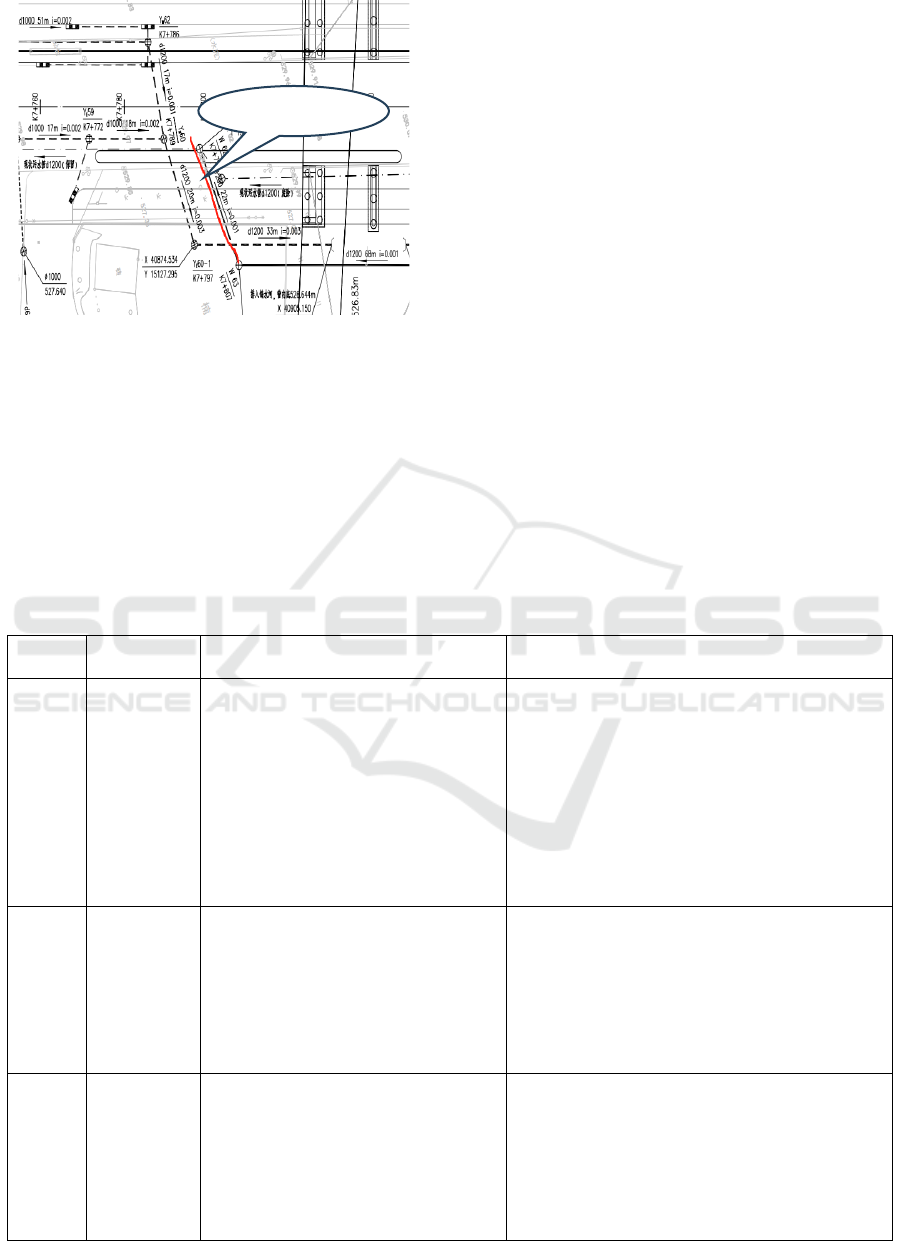
Figure 1: Location of the project.
2.2 Scheme Comparison and Selection
We have compared three construction methods,
namely the diaphragm wall excavation scheme, the
row - pile support method, and the steel sheet pile
construction method. On the basis of considering
various factors such as the specific characteristics of
the project, construction period, and cost, the steel
sheet pile construction method has been selected. A
comparative analysis of the three construction
schemes has been carried out in terms of construction
difficulty, project cost, applicability, etc., as shown in
Table 1.
2.3 Overall Project Layout Deployment
T Nanqiao Bridge spans a local natural river. The
river flows from the northwest to the southeast. The
width of the river section at Nanqiao ranges from 10.0
to 30.0 meters, and the depth is approximately 4.5 to
5.0 meters. Both banks are protected by mortar - laid
strip - stone slopes. During the survey, there was a
small amount of flowing water in the river, with a
water depth of 0.5 to 1.5 meters. The excavation of
the pipe gallery is close to the river. Soft muddy soil,
as well as layers of eggs and gravel, are distributed on
the surface. Surface water is well - developed.
According to the comparison of the schemes in Table
1, it can be concluded that from the perspectives of
construction safety, investment, and dewatering, the
steel sheet pile method is preferentially selected for
foundation pit support.
Table 1: Comparison Table of Excavation Support Plans.
Serial
Numbe
r
plans applicability Feasibility analysis based on on-site conditions
1
Underground
continuous
wall
(1) For deep foundation pit engineering
projects, the excavation depth generally
exceeds 10m.
(2) There are safety - protected
buildings or structures in the vicinity.
(3) The space within the deep
foundation pit is relatively limited.
(4) The top - down construction method
is adopted.
The disposal of waste slurry is highly inconvenient.
As a temporary retaining structure, the diaphragm
wall incurs higher costs compared to other
methods. In case of an inappropriate construction
method or special construction geological
conditions, misalignment and seepage may occur at
the ends of adjacent wall segments. In this project,
there are soft muddy soils and alluvial layers
containing boulders. The soft muddy soils are fluid,
which increases the construction difficulty and
p
oses si
g
nificant construction risks.
2 Row pile
(1) Foundation pits are classified into
three safety levels: level - one, level -
two, and level - three foundation pits.
(2) It is mostly applied to the support of
basements with poor - quality soil for
excavation, complex surroundings
around the foundation pit, and relatively
dee
p
excavation.
In this project, the row - pile support generally
comes with a relatively high cost. Additionally, the
excavation site has limited space, the groundwater
level is high, and there are stringent requirements
for construction personnel and equipment.
3
Steel sheet
pile
(1) It is applicable to construction sites
where the amount of earthwork for
foundation pit excavation is small,
mechanized construction operations can
be carried out smoothly, and drainage is
unobstructed.
From the perspectives of cost - saving, construction
convenience and the characteristics of the
construction site itself in this project, steel sheet
piles can be reused. They can be easily driven into
soft muddy soil and clay. Steel sheet piles have
excellent water - retaining performance, high
adaptability, reliable quality, and can bring high
economic benefits.
the
p
ro
j
ect
Application of Comprehensive Construction Technology for Steel Sheet Piles in High Water Level Highway Foundation Pit Engineering
with Saline Soil in Confined Space
93
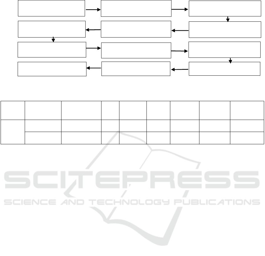
Figure 2: Schematic diagram of steel sheet pile process flow.
Table 2: Standardize slope ratio.
name slope height
Saline filled
soil
silt
Medium
sand
Loose
pebbles
Slightly
dense
p
ebbles
Medium
density
p
ebbles
Dense
pebbles
Slope
rate
H<5m 1:2 1:2.5 1:1.5 1:1.25 1:1 1:0.75 1:0.5
H=5~10m 1:2 1:3.0 1:1.5 1:1.5 1:1.25 1:1 1:0.75
H represents the height of slope or foundation pit excavation, measured in meters.
2.4 Construction Scheme
The depth of the foundation pit in this project is
approximately 4.7 - 7.7m. The backfill, silt, and sand
layers on the foundation trench walls have a loose
structure, classifying this as a "high - risk project".
Appropriate measures should be taken to ensure the
safe construction of the foundation trench. It is
recommended to adopt an excavation plan combining
slope-setting with temporary support. There are a
large number of underground pipelines distributed on
both sides of the original municipal roads near the
project site. These mainly include water supply,
sewage, rainwater, gas, power, and communication
pipelines, with a burial depth of around 0.7m-7.7m.
Therefore, it is proposed to conduct surveys and
marking of underground pipelines before
construction, formulate key protection plans, and
move or remove pipelines that may affect
construction when necessary to ensure construction
safety. In practice, protection measures should be
implemented according to the actual situation at the
construction site, such as using reinforcement
treatment. Based on the characteristics of this project
and the survey data, the technological process is
shown in Figure 2. The slope ratios of various soils
for the building slope are specified as shown in Table
2.
2.5 Construction Plan
Before connecting the new pipeline to the old sewage
pipeline, a confined - space operation plan should be
formulated. After it is approved, the operation must
be carried out strictly in accordance with the
requirements of the plan. Provide safety and technical
training to the operating personnel, distribute labor
protection supplies, and ensure an adequate supply of
emergency response items. Before the operation,
conduct gas detection and ventilation of the old
pipeline. The operation can only commence once the
conditions meet the requirements. During the
operation, assign dedicated personnel to monitor and
conduct continuous gas detection in the working area.
For the personnel involved in pipeline connection
work, arrange for two or more workers to carry out
the construction simultaneously.
3 SAFETY CALCULATION OF
STEEL SHEET PILE
ENCLOSURE STRUCTURE
According to the excavation specifications for steel
sheet piles, it is necessary to convert the uniformly
distributed load within a certain range on the outer
Measurement, laying out, and
positioning of steel sheet piles
Construction of surrounding
intercepting ditches
Dig trenches
Install guide beam
Construction of steel sheet piles
Dismantle the guide beam
earth excavation
Supporting construction
Pipeline construction
Backfilling construction
Remove the steel sheet pile
Gap treatment after steel sheet
p
ile removal
ICESCE 2024 - The International Conference on Environmental Science and Civil Engineering
94

side of the steel sheet pile into a certain height of the
soil column,
ℎ
= 𝑞/𝛾 = 20𝑘𝑃a/20kN/m
=1.0𝑚, ℎ
—
𝑐𝑜𝑛𝑣𝑒𝑟𝑡 𝑡ℎ𝑒 ℎ𝑒𝑖𝑔ℎ𝑡 𝑜𝑓 𝑡ℎ𝑒 𝑠𝑜𝑖𝑙 𝑐𝑜𝑙𝑢𝑚𝑛 , q — the
load around the foundation pit,
𝛾— 𝑐𝑜𝑛𝑣𝑒𝑟𝑡 𝑡ℎ𝑒 𝑤𝑒𝑖𝑔ℎ𝑡 𝑜𝑓 𝑡ℎ𝑒 𝑠𝑜𝑖𝑙, the design
adopts 12 m Larson steel sheet piles, Minimum depth
of steel sheet pile into soil: H
min
=1.2 ×
(0.53+1.53)=2.5 m, Length of steel column:
L=2.5+5.0=7.5 m, Compliant with regulatory
requirements.
3.1 Construction Process of Steel Sheet
Piles
(1) Prepare the pile driving machine.
(2) During concrete pouring, first use machinery
to lift the sheet piles to the pile - insertion point for
pile insertion. Align them manually and precisely aim
at the pile - insertion port. Then, construct the steel
sheet piles one by one using the driving method. To
ensure the vertical angle, two levels are used for
control. Set up a fastening plate at the lock - mouth of
the steel sheet piles in the correct direction of the piles.
Once the piles are inserted in place, immediately weld
and fix them to the steel purlins with steel bars or steel
plates.
(3) When driving the steel sheet piles, if there are
gaps at the joints due to tilting, special - shaped sheets
with a wider upper part and a narrower lower part, or
with a width exceeding or less than the standard
distance are generally used for adjustment. If
processing is difficult, the center - line modification
method can also be adopted for correction.
(4) When vibrating and driving into the soil layer,
if there are crushed stones thrown into the foundation,
the vibrating pile - driving construction can be used
to pull out the piles first, and then drive them again.
Vibrate up and down and drive several times until the
piles are successfully driven in.
(5) Drive each pile into the soil layer in turn. At
the same time, pay attention to the accurate
positioning and alignment of the lock - mouths to
ensure the construction quality. Measure and
determine the position of the sheet piles according to
the construction drawings and install the guide frame
(the guide frame consists of guide beams and purlin
piles).
3.2 Common Issues in Steel Sheet Pile
Construction
Accurately measure and determine the position of the
sheet piles according to the construction drawings and
install the guide frame. The guide frame is composed
of guide beams and steel purlins.
(1) Use a level and a leveling instrument to control
and adjust the position of the guide light.
(2) The height of the beam should be appropriate,
reserving a certain height space for steel sheet pile
construction and improving work efficiency.
(3) As the steel sheet piles are poured, the guide
beam should not sink or deform.
(4) The position of the slide rail should be as
vertical as possible and should not collide with the
steel sheet piles.
4 CONCLUSION
This paper takes the high-water-level foundation pit
project of the pipe gallery in the Chengdu-Pengzhou
Road Reconstruction and Expansion Project as an
example to study the practical application effect of
the comprehensive construction technology of steel
sheet piles in dealing with high - water - level
foundation pits.
(1) Steel sheet piles can better meet the
requirements of urban noise reduction, green energy
conservation. They have advantages such as high
utilization rate of urban space, good economy, safety,
and stability, as well as convenient operation. They
are suitable for comprehensive operations in urban
foundation pit construction spaces with limitations (in
terms of height). They are particularly applicable to
urban foundation pit projects with high groundwater
levels, high construction risks, and limited space.
AUTHOR CONTRIBUTION
Xiyuan Liu: conceptualization, methodology, data
curation, writing-original draft preparation. Shanzhi
Fan: review & editing.
FUNDING INFORMATION
This paper is supported by Key R&D Program of
Gansu Provincial Department of Science and
Technology - Industrial Category (23YFGA0018).
DATA AVAILABILITY
The data used to support the findings of this study are
Application of Comprehensive Construction Technology for Steel Sheet Piles in High Water Level Highway Foundation Pit Engineering
with Saline Soil in Confined Space
95

available from the corresponding author upon request.
CONFLICTS OF INTEREST
We declare that we do not have any commercial or
associative interest that represents a conflict of
interest in connection with the work submitted.
REFERENCES
Xu, Z. L. 2016. Elasticity. Higher Education Press, Beijing.
Vol. 58, Issue 11, pages 76-80.
Jiang, Y. 2004. Research on Prediction, Forecasting and
Countermeasures of Large Deformation of Surrounding
Rock in Highway Tunnels. Chengdu University of
Technology, Chengdu.
Yu, Y. 1998. The mechanism and determination method of
large deformation in compressive rock support. World
Tunnel, (01): 46-51.
Zhang, Z. D. 2003. Exploration and Research on Large
Deformation of Squeezing Surrounding Rock Tunnels.
Modern Tunnel Technology, (02): 5-12+40.
Ding, X. L., Zhang, Y. T., Huang, S. L., et al. 2023,
Mechanism of Large Deformation of Tunnel
Surrounding Rock, Prediction and Application of
Squeezing Large Deformation. Journal of Rock
Mechanics and Engineering, 1-24.
Liu, Z. C., Zhu, Y. Q., Li, W. J., Liu, P. X., et al. 2008.
Research on the Mechanism and Grading Standards of
Large Deformation in Squeezing Surrounding Rock
Tunnels. Journal of Geotechnical Engineering, (05):
690-697.
Fei, W. P., Zhang, J. M., Cui, H. L., et al. 2012. Analysis of
Large Deformation Mechanism of Surrounding Rock
during Construction of Deep Underground Caverns.
Journal of Rock Mechanics and Engineering, 31 (S1):
2783-2787.
He, M. C., Peng, T., Chen, Y. J. 1994. Large deformation
problems and research methods in soft rock engineering.
Hydrogeology and Engineering Geology, (05): 5-8.
Kang, Y. S., Geng, Z., Liu, Q. S., et al. 2022. Research
progress on control technology and methods for large
deformation disasters in soft rock in China. Rock and
Soil Mechanics, 43 (08): 2035-2059.
He, M. C. 2014. Research progress and challenges in deep
soft rock engineering. Coal Journal, 39 (08): 1409-
1417.
The Second Survey and Design Institute of the Ministry of
Railways. 1997. Stability and Support Technology of
High Stress Ratio Coal bearing Strata Roadways
(Research Report). The Second Survey and Design
Institute of the Ministry of Railways, Chengdu.
Wang, R. 2003. Research on the Mechanism and Prevention
Measures of Large Deformation of Surrounding Rock in
Zhegushan Tunnel of National Highway 317. Chengdu
University of Technology, Chengdu.
Wei, L., Liu, Q., Huang, P. 2017. A review of research on
the mechanism and control measures of large
deformation in high stress soft rock tunnels. Highway,
62 (07): 297-306.
Wang, Y. 2022. Research on Large Deformation Control
Technology of Soft Surrounding Rock in Qingyunshan
Tunnel. Value Engineering, 41 (29): 106-108.
Liu, G., Zhang, F. Y., Li, X. Z., et al. 2005. Characteristics
and Mechanism Analysis of Large Deformation in
Muzhailing Tunnel. Journal of Rock Mechanics and
Engineering, (S2): 5521-5526.
Chen, S. H., Li, Z. P., Ma D. 2017. Xinguanjiao Tunnel on
Qinghai Tibet Railway. Tunnel Construction, 37 (07):
907-911.
Li, J. L. 2014. Rock Mechanics. Chongqing University
Press: A Series of Textbooks for Undergraduate
Guidance Professional Standards in Civil Engineering
for Higher Education Institutions, 318.
Wang, W. J., Dong, E. Y., Yuan, C., et al. 2017. Research
Progress on Anchor Rod Support Theory and
Technology for Deep and Large Deformation Tunnels.
Mining Engineering Research, 32 (02): 1-10.
Fu, Q., Ming, A. X. 2007. Mechanism of anchor rod (cable)
span reduction and its application in deep buried large-
span tunnels. China Mining, (05): 64-65+68.
Yuan, Y. 2016. Research on High Ground Stress Soft Rock
Large Deformation Control Technology for Lanxin
Second Line Daliang Tunnel. Southwest Jiaotong
University, Chengdu.
Yang, S. S., Kang, L. X. 2002. Summary and Prospect of
Research on Anchor Rod Support in Coal Mine
Roadways. Journal of Taiyuan University of
Technology, (04): 376-381.
ICESCE 2024 - The International Conference on Environmental Science and Civil Engineering
96
