
Hydraulic Fracturing Test of Clay Core in Earth-Rock Fill Dam with
the Potential Weak Links
Qimeng Chen
a
, Jianming Xu
b
, Bin Huang
*c
, Boyang Chen
d
, Lei Ye
e
and Xi Zhao
f
School of Architecture and Civil Engineering, Huizhou University, China
*
Keywords: Hydraulic Fracturing, Triaxial Hydraulic Fracture Test, Clay Core.
Abstract: Hydraulic fracturing is of great concern in earth-rock dam engineering and is also one of the hot research
issues in earth core dams. Hydraulic fracturing can cause the destruction of the dam's anti-seepage body and
cause catastrophic consequences. This paper uses a triaxial hydraulic splitting test to quantitatively describe
the shape of hydraulic fractures in clay core, and further demonstrates the occurrence mechanism of hydraulic
fracturing from a microscopic perspective. Hydraulic fracturing is ultimately a deformation problem. Due to
the compressive deformation of the soil, the initial fracture takes an elliptical shape in the two-dimensional
space, thus producing a wedge splitting effect on the fracture tip.
1 INTRODUCTION
In earth-rock fill dam engineering, accidents caused
by hydraulic fracturing often lead to the destruction
of the dam's anti-seepage body, thus causing
catastrophic consequences. (Seed et al., 1976) and
(Wilson et al., 1984) both pointed out that hydraulic
fracturing is the occurrence and development of
cracks in soil.
There are many reasons for hydraulic fracturing
of the clay core in earth-rock fill dam. (Lowe et al.,
1970) classified cracks in dams into vertical cracks
caused by uneven settlement, horizontal cracks
caused by arching effects, shrinkage cracks caused by
water loss in the dam body, etc. (Sherard et al., 1973)
pointed out that cracks are a common problem in
earth-rock dams, which can occur during the
construction of the dam or after it is built. Based on
the assumption that there is a splitting failure zone in
the core wall, Lo and (Kaniaru et al., 1990)
analysed
the hydraulic fracturing characteristics of five earth-
rock dams including Balderhead, Hyttejuvet,
Viddalsuatu, Teton and Yard’s Creek. (Alfaro et al.,
a
https://orcid.org/0009-0005-9978-1453
b
https://orcid.org/0009-0006-5601-1616
c
https://orcid.org/0000-0002-1344-5733
d
https://orcid.org/0009-0001-7410-4318
e
https://orcid.org/0009-0003-7526-0798
f
https://orcid.org/0009-0003-1819-6638
2001; Wong et al., 2001) pointed out that hydraulic
fracturing pressure is not only related to the overlying
pressure at the location where hydraulic fracturing
cracks occur, but also related to the strength of the
soil and inherent cracks or defects. (Murdoch et al.,
2002) pointed out that the characteristics of shallow
hydraulic fractures obtained through excavation and
drilling cannot meet the needs of predicting the
development of hydraulic fractures. (Au et al.,
2003) used a modified consolidation instrument
to conduct hydraulic fracturing tests on kaolin
samples. Hydraulic fracturing tests were
conducted with liquids of different viscosities
under different consolidation states was analysed.
The influence of factors such as ratio and
boundary conditions on hydraulic fracturing.
These scholars have studied the quantitative
relationship between hydraulic pressure and
various influencing factors during hydraulic
fracture failure, but most of them focused on
drilled cylinders or square specimens.
In view of the potential weak links in the clay core
of earth-rock fill dam, this paper conducts
60
Chen, Q., Xu, J., Huang, B., Chen, B., Ye, L., Zhao and X.
Hydraulic Fracturing Test of Clay Core in Earth-Rock Fill Dam with the Potential Weak Links.
DOI: 10.5220/0013573400004671
In Proceedings of the 7th International Conference on Environmental Science and Civil Engineering (ICESCE 2024), pages 60-65
ISBN: 978-989-758-764-1; ISSN: 3051-701X
Copyright © 2025 by Paper published under CC license (CC BY-NC-ND 4.0)
experimental simulations through pre-existing cracks
to study the hydraulic fracture of the clay core, and
establishes the influence of various physical,
mechanical and other factors on the hydraulic
fracturing characteristics, including hydraulic
pressure, various factors and fracture dimensions.
2 TRIAXIAL HYDRAULIC
FRACTURING TEST
2.1 The Properties of Clay
The material used in this paper is low plastic clay,
with the liquid limit of 36% and the plastic index of
21%. The maximum dry density of light compaction
is 1.78 g/cm
3
and the optimum moisture content is
16.6%. The specimen was prepared with the
compaction degree of 98%, and the permeability
coefficient is 1.1×10
-6
cm/s. Particle-size distribution
and constitutive parameters are shown in Figure 1
and Table 1.
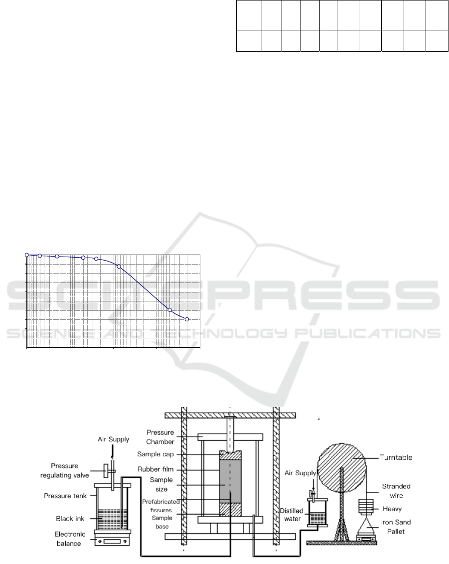
Figure 1: Particle-size distribution curve of clay.
Table 1: The parameters of Duncan-Chang model for clay.
c
CD
(kPa)
φ
CD
(
o
)
K n K
b
m F G R
f
D
60.7 19.6
139.
9
0.33
8
52.3 0.185 0.126 0.296 0.836 3.513
2.2 Triaxial Hydraulic Fracturing Test
The aim of triaxial hydraulic fracturing test is to study
the law of hydraulic fracturing of soil under confining
pressure and to obtain the failure mode of hydraulic
fracturing. The effects of saturation, compactness,
consolidation ratio, confining pressure, dimension of
pre-existing fracture and loading rate of hydraulic
pressure are studied.
As shown in Figure 2, the test device consists of
three parts: a triaxial apparatus in the middle, a water
intake measuring device for fracturing pressure on
the left and an external variable measuring device for
confining pressure on the right. The specimen with
fracture is installed in the triaxial apparatus, the
specimen is wrapped in rubber membrane, the
pressure chamber is linked with the confining
pressure device, and the base of the specimen is
linked with the pressure water inlet device.
The triaxial hydraulic fracturing test can simulate the
stress state such as confining pressure and
consolidation ratio of the specimen, and it is an ideal
research method. The triaxial fracturing tests are
carried out in the aspects of saturation, compactness,
consolidation ratio, confining pressure, dimension of
pre-existing fracture and hydraulic pressure loading
rate. The test program is shown in Table 2, with a
compaction degree of 98%; the dimensions of pre-
existing fracture are shown in Figure 3.
Figure 2: Diagram of triaxial hydraulic fracturing test device.
0
10
20
30
40
50
60
70
80
90
100
0.0010.010.1110
Percent finer (%)
Particle size (mm)
Hydraulic Fracturing Test of Clay Core in Earth-Rock Fill Dam with the Potential Weak Links
61
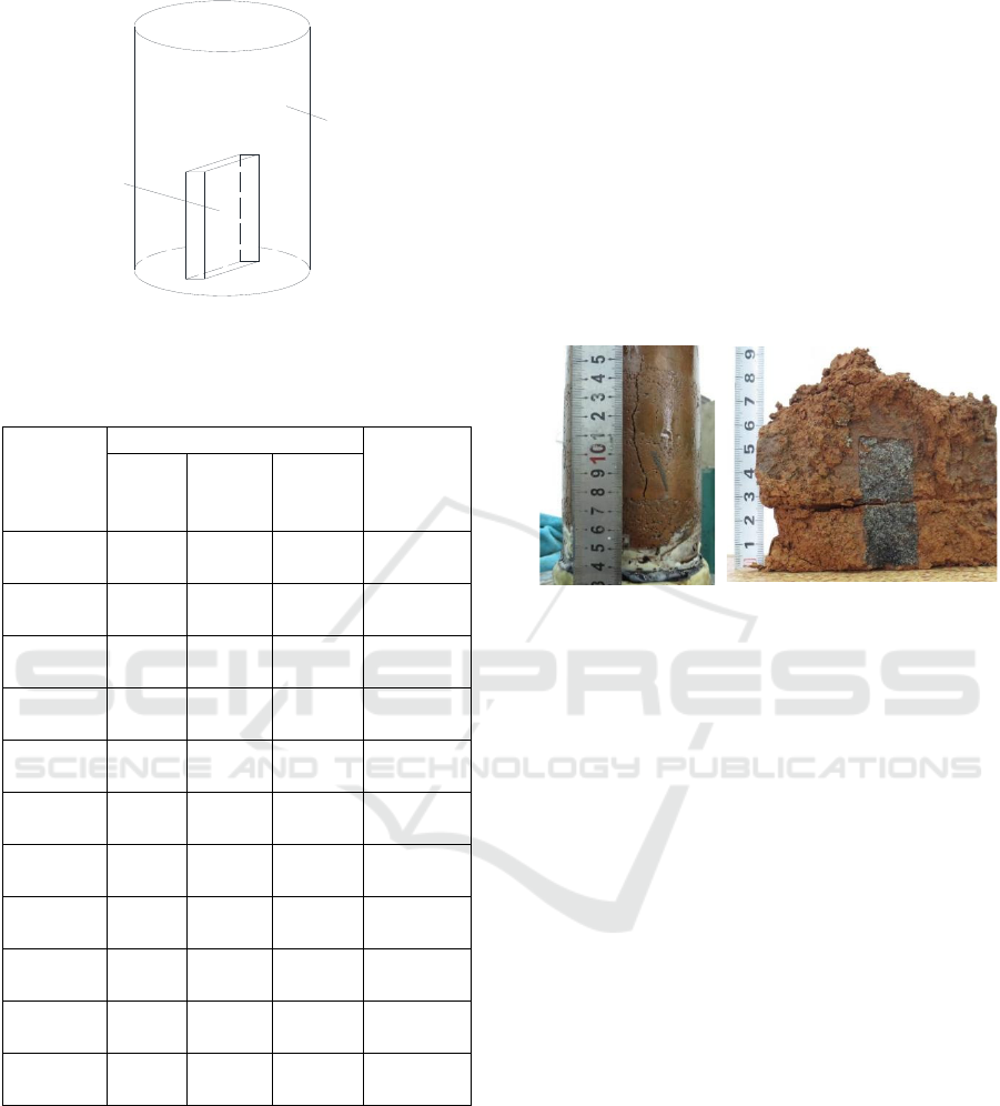
Figure 3: Dimensions of pre-existing fracture in specimens.
Table 2: Testing program of triaxial hydraulic fracturing for
clay with pre-existing fracture.
No. of
sample
Dimension of fracture
Confinin
g
Pressure
(kPa)
Depth
(mm)
Lengt
h
(m
m
)
Openin
g (mm)
SLPL-
11
50 20 2 50
SLPL-
12
50 20 2 200
SLPL-
13
50 20 2 350
SLPL-
14
50 20 2 100
SLPL-
15
50 20 2 350
SLPL-
16
50 20 2 200
SLPL-
17
100 20 2 200
SLPL-
18
150 20 2 200
SLPL-
19
50 35 2 200
SLPL-
20
50 50 2 200
SLPL-
21
50 20 4 200
2.3 Results Analysis
The development of hydraulic fracture in SLPL-15
specimen is shown in Figure 4. The sample size is
φ101 mm × H200 mm, and the pre-existing fracture
dimension is 50mm in depth × 20mm in length ×
20mm in opening. Consolidate for 48 hours under a
confining pressure of 350kPa. After starting the test,
the pore pressures are 50, 80, 120, 160, 200, 230, 270,
310, 350, and 390kPa. Each level of pressure lasts for
10 to 15 minutes until the change rate of the balance.
At 430 kPa pore pressure for 4 min, the specimen was
destroyed, ink gushed from the splitting crack, the
valve was closed, and the test was stopped. There are
three distinct long fractures and several small
fractures around the specimen. The apparent fracture
length of the sample is about 11 cm, which is larger
than the ink length inside the sample, and greater than
the depth of the pre-existing cracks by 5 cm. And the
depth of ink staining directly above the pre-existing
fracture is about 2 cm, which is shown that hydraulic
fracturing occurred to some extent along the fracture
depth.
(a) Sample surface
fracture
(b) Development of internal
fracture
Figure 4: Development of hydraulic fracture.
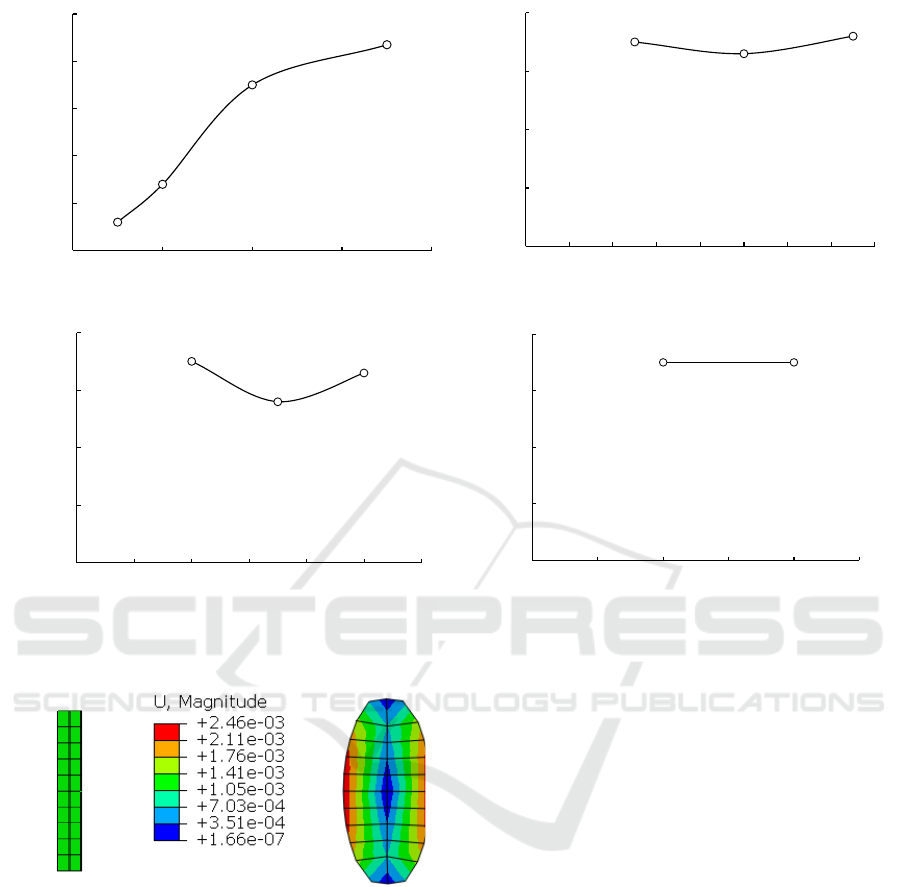
The results of hydraulic fracturing tests are shown
in Table 3, and the curves of fracturing pressure
versus confining pressure, fracture depth, fracture
length and fracture opening are shown in Figure 5. It
can be obtained as follows:
(1) the law of failure pressure and confining
pressure of hydraulic fracturing is the most
obvious. The bigger confining pressure is, the
bigger fracturing pressure is, but the increasing
trend of fracturing pressure is gradually slowing
down. When the confining pressure is below
200 kPa, the fracture pressure and confining
pressure increase linearly, and when the
confining pressure is over 400 kPa, the fracture
pressure shows an asymptotical trend and does
not increase linearly.
(2) the fracture pressure has little relation with
fracture depth, the fracture depth varies from
50mm to 150mm, and the fracture pressure
fluctuates very little, which is due to the fact that
the triaxial hydraulic fracturing test is basically
a failure mode of fracture propagation in the
direction of fracture length, although there is
fracture propagation along the depth of the
fracture, the fracture in the length direction
penetrates before the fracture in the depth
Opening
Depth
Length
Clay sample
Fracture
ICESCE 2024 - The International Conference on Environmental Science and Civil Engineering
62

direction, so it shows that the fracture depth has
little effect on the fracture pressure.
(3) the relationship between fracture pressure and
fracture length is not significant. The
deformation characteristics of the pre-placed
fracture after fracturing pressure is elliptic (as
shown in Figure 6) , and the two ends are the tip
of the fracture, which are subjected to the tensile
force caused by the fracturing pressure, and the
two sides of the fracture are subjected to the
total splitting tensile force, this tension is borne
by a fracture-free soil.
(4) The longer the fracture, the lower the tension at
the tip of the fracture, but the greater the total
splitting tension on both sides of the fracture.
For this test, the longer the precast joint is, the
smaller the effective range of the soil which can
bear the total splitting tension is, but the test
result does not reflect the rule that the longer the
joint is, the smaller the splitting failure pressure
is, it should not belong to the simple tensile
failure mode of soil. Therefore, it is proposed
that the failure mode of the fracture tip is
gradually tensile fracturing. Although the stress
at the fracture tip is greater under the condition
of the shorter fracture, the stress at the fracture
tip decreases gradually with the extension of the
fracture length, when the fracture is extended to
a certain extent, it is close to the condition of the
fracture length, and the stress at the fracture tip
should be close to it.
(5) It is assumed that the equivalent fracture length
after fracture propagation is the sum of the
initial fracture length and the fracture length
after fracture propagation, according to the
Irwin equivalent fracture correction method in
fracture mechanics, the displacements in this
region will be released after the fracture appears,
and there may be relative displacements on the
upper and lower surfaces of the yield region,
resulting in displacements, free water is allowed
to transmit pressure inside, so the equivalent
fracture length is also assumed for hydraulic
fracturing of clay materials.
(6) the failure pressure of hydraulic fracturing has
little relation with the fracture opening,
provided that the pressure water can move
freely in the pre-existing fracture. This is
reflected in the clay core, no matter how big or
how small the opening of the fractures, as long
as the reservoir water can move freely and
transmit pressure in the weak links, there is a
possibility of hydraulic fracturing.
(7) when confining pressure is greater than 350 kPa,
hydraulic fracturing occurs to some extent along
the depth of the fracture, and the corresponding
fracturing pressure is 430 ~ 440 kPa, if the
deformation without restraint is large at the
middle and small at the two ends, thus causing
the tensile force at the fracture tip, the fracture
propagation will occur not only in the direction
of the precast fracture length under the larger
fracture pressure, but also in the direction of the
precast fracture length, in the depth direction of
the fracture also appears to expand, but the
length direction of the fracture first through,
resulting in hydraulic fracturing did not
continue to expand to the depth direction. In the
core-wall Dam project, the fracture depth
direction of the expansion of greater harm, more
attention should be paid.
Table 3: Results of triaxial hydraulic fracturing test on clay with potential fracture.
No. of sample
Dimensions of fracture Confining
pressure
(kPa)
Fracture
pressure (kPa)
Depth (mm) Length (mm) Opening (mm)
SLPL-11 50 20 2 50 60
SLPL-12 50 20 2 200 360
SLPL-13 50 20 2 350 440
SLPL-14 50 20 2 100 140
SLPL-15 50 20 2 350 430
SLPL-16 50 20 2 200 340
SLPL-17 100 20 2 200 330
SLPL-18 150 20 2 200 360
SLPL-19 50 35 2 200 280
SLPL-20 50 50 2 200 330
SLPL-21 50 20 4 200 350
Hydraulic Fracturing Test of Clay Core in Earth-Rock Fill Dam with the Potential Weak Links
63
(a) (b)
(c) (d)
Figure 5: The curves of hydraulic fracturing pressure vs. fracture size.
(a) Before
deformation
(b) After deformation
Figure 6: Deformation characteristics of fractures before
and after fracturing pressure is applied.
3 CONCLUSIONS
Hydraulic splitting is ultimately a deformation
problem. Due to the compressive deformation of the
soil, the initial fracture takes an elliptical shape in the
two-dimensional space, thus producing a wedge
splitting effect on the fracture tip. The damage
pressure of hydraulic fracturing has little relationship
with the fracture opening. In the core wall, no matter
how big or small the thickness of the fracture is, as
long as the reservoir water can move freely and
transmit pressure in the fracture, there is a possibility
of hydraulic splitting. Define the ratio of fracture
opening to equivalent fracture length as the
discriminant factor of hydraulic splitting. By
comparing the relationship between this factor and
the critical value, you can make a process judgment
on whether hydraulic splitting occurs.
ACKNOWLEDGMENTS
This study was supported by Guangdong Province
Undergraduate Innovation and Entrepreneurship
Project (Grant No. S202310577066 &
S202210577064), Undergraduate Online Courses
Committee of University in Guangdong Province
(Grant No. 2022ZXKC437), and Guangdong
Provincial Education and Scientific Research Project
-Higher Education Scientific Research Special Topic
(Grant No. 2023GXIK504).
0
100
200
300
400
500
0 100 200 300 400
Fracuring pressure(kPa)
Confining pressure(kPa)
0
100
200
300
400
0 20 40 60 80 100 120 140 160
Fracuring pressure(kPa)
Depth of fracture(mm)
0
100
200
300
400
0 102030405060
Fracuring pressure(kPa)
Length of fracture(mm)
0
100
200
300
400
012345
Fracuring pressure(kPa)
Opening of fracture(mm)
ICESCE 2024 - The International Conference on Environmental Science and Civil Engineering
64

REFERENCES
Seed, H. B., 1976. Hydraulic fracturing and its possible role
in the Teton Dam failure[R]. Appendix D of Report to
U.S. Dept. of the Interior and State of Idaho on Failure
of Teton Dam by Independent Panel to Review Cause
of Teton Dam Failure, 1-39.
Wilson, C., 1984. Hydraulic fracturing in embankment
dams and available defensive measures[C]//
Proceedings of the eighth Regional Conference for
Africa on SMFE, Harare, 491-500.
Lowe, J., 1970. Recent development in the design and
construction of earth and rockfill dams[C]//
Proceedings of 10th International Congress on Large
Dams, Montreal, Canada, 11-23.
Sherard, J. L., 1973. Embankment dam cracking. In :
Embankment dam Engineering, Casagrande
Volume[M]. Edited by Hirschfeld R C and Poulos S J,
New York: John Wiley and Sons, 271-353.
Lo, K. Y., Kaniaru, K., 1990. Hydraulic fracture in earth
and rockfill dam[J]. Canadian Geotechnical Journal,
27(4): 496-506.
Alfaro, M. C.,Wong, R. C. K., 2001. Laboratory studies on
fracturing of low permeability soils[J]. Canadian
Geotechnical Journal, 38(2), 303-315.
Wong, R. C. K., Alfaro, M. C., 2001. Fracturing in low-
permeability soils for remediation of contaminated
ground[J]. Canadian Geotechnical Journal, 38(2),
316-327.
Murdoch, L. C., 2002. Mechanical analysis of idealized
shallow hydraulic fracture[J]. Journal of Geotechnical
and Geoenvironmental Engineering, ASCE, 128(6):
488-495.
Au, S. K. A., Soga, K., Jafari, M. R., Bolton, M. D. and
Komiya, K., 2003. Factors affecting long-term
efficiency of compensation grouting in clays[J].
Journal of Geotechnical and Geoenvironmental
Engineering, ASCE, 129(3): 254-262.
Hydraulic Fracturing Test of Clay Core in Earth-Rock Fill Dam with the Potential Weak Links
65
