
Research on Vibration Characteristics of Powerhouse Structure of
Variable Speed Unit Section in Fengning Pumped Storage Power
Station
Guoqing Liu
1,* a
, Lianghua Xu
1
, Xin Jia
2
and Chunlei Wei
3
1
State Key Laboratory of Simulation and Regulation of Water Cycle in River Basin, China Institute of Water Resources and
Hydropower Research, Beijing 100048, China
2
Hebei Fengning Pumped Storage Co., Ltd., Chengde 068350, China
3
State Grid Xinyuan Group Co., Ltd., Beijing 100032, China
Keywords: Pumped Storage Power Station, Powerhouse Structure, Vibration Characteristics, Natural Frequency,
Vibration Control Standard.
Abstract: Taking the powerhouse of 12# variable speed unit section in Fengning pumped storage power station as a
research object, a three-dimensional finite element model of the powerhouse structure was established.
Firstly, the modal analysis method was used to calculate and research the natural vibration characteristics of
whole and local structures of the powerhouse. Then, based on the field measured pressure pulsation data, the
vibration responses of the powerhouse structure were simulated under the action of hydraulic vibration
source. And referring to the relevant vibration control standard of powerhouse, the vibration responses of
the powerhouse were analyzed and evaluated. The results show that the top 20 natural frequencies of the
whole structure of the powerhouse range from 13.71 to 34.00 Hz, and the top 3 vibration modes are mainly
the whole vibration of the structure above the volute layer. The calculation values of natural frequencies of
the busbar floor and pillars are not significantly different from the measured values, indicating that the
establishment of the calculation model and the setting of the boundary conditions are reasonable and
effective. The maximum vibration responses of local structures of the powerhouse meet the vibration
control standard of powerhouse under pumping and generating conditions.
a
https://orcid.org/0009-0005-8512-4049
1 INTRODUCTION
Pumped storage power station is a green, low-
carbon, clean and flexible regulated power supply
with the most mature technology, the best economy
and the greatest potential for large-scale
development (Zhou et al., 2023). With the
development and needs of pumped storage power
station construction, pump turbine unit is developing
towards the direction of ultra-high head, large
capacity, high speed and variable speed. As the
supporting structure of unit, the powerhouse of
hydropower station may experience whole or local
vibration when subjected to exciting forces such as
mechanical force, electromagnetic force and
hydraulic force generated during the operation of
unit (Gao et al., 2023). At present, vibration
problems have been occurred on powerhouse
structures of many pumped storage power stations in
China when they are operating (Wang et al., 2023).
Therefore, in-depth research on vibration
characteristics of powerhouse is of great significance
to effectively avoid the harmful vibration that may
occur on the structure.
This paper took the powerhouse structure of 12#
variable speed unit section in Fengning pumped
storage power station as a research object. After
completing the analysis of natural vibration
characteristics of whole and local structures of the
powerhouse, the vibration responses of the
powerhouse structure under pressure pulsation were
calculated, and the vibration safety of the
powerhouse was analyzed and evaluated according
to the vibration control standard of powerhouse. It is
Liu, G., Xu, L., Jia, X., Wei and C.
Research on Vibration Characteristics of Powerhouse Structure of Variable Speed Unit Section in Fengning Pumped Storage Power Station.
DOI: 10.5220/0013573000004671
In Proceedings of the 7th International Conference on Environmental Science and Civil Engineering (ICESCE 2024), pages 31-36
ISBN: 978-989-758-764-1; ISSN: 3051-701X
Copyright © 2025 by Paper published under CC license (CC BY-NC-ND 4.0)
31

expected that the research results can provide a
scientific basis for the design and safe operation of
pumped storage power station.
2 CALCULATION MODEL AND
PARAMETERS
2.1 Project Overview
Fengning pumped storage power station is located in
the west of Chengde, Hebei Province, China. A total
of 12 units with a capacity of 300 MW are installed
in the main powerhouse, of which 11# and 12# units
are variable speed units. Below the generator layer is
an integral cast concrete structure, which is divided
into six layers, including draft tube layer, volute
layer, volute interlayer, turbine layer, busbar layer
and generator layer from bottom to top. The power
station adopts a structural type of one unit and one
joint, and structural joints are set between the
installation site and main powerhouse, and between
the auxiliary powerhouse and main powerhouse.
2.2 Finite Element Model
The powerhouse structure of 12# variable speed unit
section is taken as a research object. X direction is
bounded by the left and right structural joints, Y
direction is taken to the upstream and downstream
side walls connected with the surrounding rock, and
Z direction is taken from the bottom of concrete
around the draft tube to the generator floor. Concrete
structures such as floors, side walls, pillars, wind
hood, turbine pier, concrete around volute and draft
tube, as well as flow channel metal structures such
as volute and draft tube are simulated in a finite
element model. All concrete structures are
segmented by three-dimensional solid elements, and
all flow channel structures are simulated by shell
elements. The finite element model of the
powerhouse structure is divided into 231100
elements and 249727 nodes, as shown in Figure 1.
The powerhouse structure is simulated by elastic
constitutive relationship, and the concrete grade is
C30. The material parameters are shown in Table 1.
Table 1: Material parameters.
Material
Elastic
modulus (GPa)
Poisson ratio
Density
(kg/m
3
)
C30 30 0.167 2500
Steel 200 0.300 7850
Figure 1: Three-dimensional finite element model of
powerhouse structure.
2.3 Boundary Conditions
The left, right and top sides of the finite element
model are set as free surfaces, and the other
boundaries (the connection parts between the
powerhouse and surrounding rock) are set as
viscoelastic artificial boundaries.
3 ANALYSIS OF NATURAL
VIBRATION
CHARACTERISTICS OF
POWERHOUSE STRUCTURE
3.1 Natural Vibration Characteristics
of Whole Structure
The calculation results of the top 20 natural
frequencies of the whole structure of the powerhouse
are shown in Table 2, and the top 3 vibration modes
are shown in Figure 2. The top 20 natural
frequencies of the whole structure of the powerhouse
range from 13.71 to 34.00 Hz. The first vibration
mode of the powerhouse is mainly X-direction
vibration of the whole structure above the volute
layer. The second vibration mode is mainly Y-
direction vibration of the whole structure above the
volute layer. The third vibration mode is mainly
torsional vibration of the whole structure above the
volute layer around Z axis. The other vibration
modes are mainly the vertical vibration in local areas
of the floors and the normal vibration in local areas
of the side walls.
ICESCE 2024 - The International Conference on Environmental Science and Civil Engineering
32
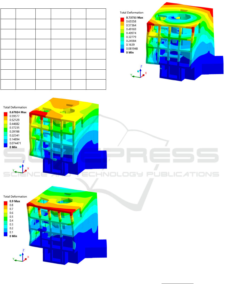
Table 2: Natural frequencies of whole structure
No.
Frequency
(Hz)
No.
Frequency
(Hz)
No.
Frequency
(Hz)
1 13.71 8 27.40 15 31.38
2 15.06 9 27.84 16 32.14
3 18.73 10 28.34 17 32.54
4 21.79 11 29.06 18 32.93
5 22.46 12 29.61 19 33.42
6 25.30 13 30.16 20 34.00
7 26.30 14 30.78
(a) First vibration mode
(b) Second vibration mode
(c) Third vibration mode
Figure 2: Top 3 vibration modes of whole structure.
3.2 Natural Vibration Characteristics
of Local Structures
Due to the complex space structure of the
powerhouse, the same vibration mode often shows
simultaneous vibration of different parts. Therefore,
it is very difficult to accurately calculate the natural
frequencies of local structures we are concerned
about by using the calculation method of natural
frequencies of whole structure. Here, the massless
foundation method is adopted, that is, the density of
all the other structures except the local structure
calculated is assigned as 0, and only their constraints
on the local structure studied are considered.
Limited by the paper length, this paper mainly
analyzes the natural vibration characteristics of the
busbar floor and pillars. For the floor, because its
horizontal vibration is relatively small, its vertical
vibration should be the focus of attention. Similarly,
for the pillars, their horizontal vibration should be
emphatically analyzed. The number of peak points
of the vertical first vibration mode of each area on
the busbar floor and the number of pillars are shown
in Figure 3, and the corresponding calculation
results of natural frequencies are shown in Tables 3
and 4. As a comparison, the field test results of
natural frequencies of the floor and pillars are also
listed in Tables 3 and 4, in which the relative error
expression between the calculation and test values of
natural frequency is
𝑅𝑒𝑙𝑎𝑡𝑖𝑣𝑒 𝑒𝑟𝑟𝑜𝑟
|
|
100% (1)
Research on Vibration Characteristics of Powerhouse Structure of Variable Speed Unit Section in Fengning Pumped Storage Power Station
33
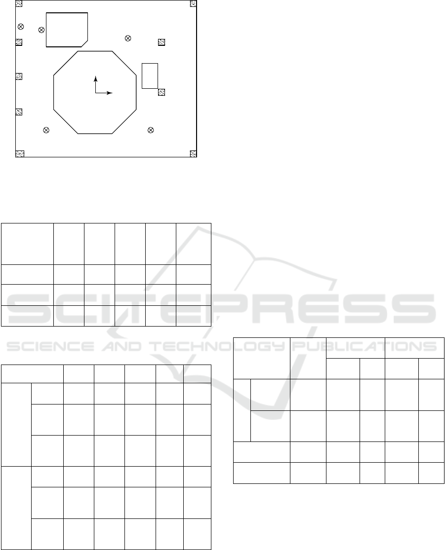
Figure 3: Numbers of peak points of vibration mode of
busbar floor and pillars.
Table 3: Vertical first natural frequency of each area on
busbar floor.
Peak point
of
vibration
mode
FB_1 FB_2 FB_3 FB_4 FB_5
Test (Hz) 46.88 32.32 43.07 76.60 111.90
Calculation
(Hz)
45.33 32.28 41.13 72.72 119.27
Relative
error
(
%
)
3.31 0.12 4.50 5.07 6.59
Table 4: Horizontal first natural frequency of each pillar
on busbar layer.
Pillar PB_1 PB_2 PB_3 PB_4 PB_5
X
directi
on
Test
(
Hz
)
— — 77.98 79.98 71.48
Calcul
ation
(Hz)
68.66 68.01 72.89 76.88 74.34
Relativ
e error
(%)
— — 6.53 3.88 4.00
Y
directi
on
Test
(Hz)
— — 71.09 79.10 81.93
Calcul
ation
(Hz)
68.27 69.30 69.66 76.20 76.71
Relativ
e error
(%)
— — 2.01 3.67 6.37
The maximum relative error between the
calculation and test values of the vertical first natural
frequencies of local areas of the busbar floor is
6.59%, and the maximum relative error between the
calculation and test values of the horizontal first
natural frequencies of the busbar pillars is 6.53%. In
general, the difference between the calculation and
test values of natural frequency of each structure is
small, indicating that the calculation model
established and the boundary conditions set in this
paper are reasonable, and the calculation method is
feasible.
4 ANALYSIS OF VIBRATION
RESPONSES OF
POWERHOUSE STRUCTURE
4.1 Vibration Control Standard of
Powerhouse
As the support system of unit, the powerhouse is
also a daily office space for the staff, so its structural
design is very important to ensure the safety and
comfort of the staff. At present, there is no unified
evaluation standard for the vibration control of
pumped storage power station powerhouse. In this
paper, the vibration control standard of powerhouse
is listed in Table 5 according to reference (Ma et al.,
2013), which can be used as a quantitative basis for
the prediction and control of powerhouse vibration.
Table 5: Vibration control standard of powerhouse.
Structure
Displace
ment
(mm)
Velocity
(mm/s)
Acceleration
(m/s
2
)
Horizont
al
Vertic
al
Horizont
al
Vertic
al
Floo
r
As
building
structure
0.2 5.0 5.0 1.0 1.0
Human
health
evaluation
0.2 5.0 3.2 1.0 0.4
Wind hood,
Turbine pie
r
0.2 5.0 5.0 1.0 1.0
Other building
structures
0.2 10.0 10.0 1.0 1.0
4.2 Analysis and Evaluation of
Vibration Responses of Powerhouse
Because the hydraulic vibration source occupies a
dominant position, this paper mainly analyzes the
vibration responses of the powerhouse structure
under the action of hydraulic vibration source. In
order to make the simulation results more accurate
and reliable, the dynamic load comes from the
measured pressure pulsation data in the flow channel,
X
Y
Z
Hanging ball
valve hole
Hanging
hole
FB_4
FB_5
FB_3
FB_2
PB_1
PB_2
PB_3 PB_4
PB_5
FB_1
ICESCE 2024 - The International Conference on Environmental Science and Civil Engineering
34

Table 6: Maximum vibration responses of local structures under pumping condition.
Structure
Displacement (μm) RMS velocity (mm/s) RMS acceleration (m/s
2
)
X Y Z X Y Z X Y Z
Generator floor 1.884 3.180 3.755 0.082 0.131 0.215 0.031 0.029 0.099
Busbar floor 1.413 2.664 3.838 0.077 0.107 0.215 0.035 0.039 0.086
Turbine floor 2.031 2.406 3.078 0.193 0.199 0.281 0.129 0.166 0.213
Wind hood 1.570 2.337 2.962 0.133 0.108 0.230 0.071 0.057 0.103
Turbine pier 1.874 2.184 2.479 0.163 0.146 0.417 0.124 0.097 0.363
Busbar pillar 1.755 3.177 1.896 0.139 0.125 0.120 0.060 0.049 0.038
Turbine pillar 1.984 2.945 1.695 0.272 0.168 0.118 0.132 0.074 0.066
Table 7: Maximum vibration responses of local structures under generating condition.
Structure
Displacement (μm) RMS velocity (mm/s) RMS acceleration (m/s
2
)
X Y Z X Y Z X Y Z
Generator floor 1.722 2.379 4.148 0.105 0.125 0.308 0.035 0.037 0.153
Busbar floor 1.075 2.031 3.977 0.113 0.140 0.229 0.057 0.056 0.098
Turbine floor 1.839 2.425 3.327 0.206 0.225 0.417 0.134 0.183 0.261
Wind hood 1.379 1.749 2.367 0.131 0.118 0.259 0.069 0.058 0.111
Turbine pier 1.629 1.719 1.987 0.182 0.148 0.445 0.133 0.101 0.388
Busbar pillar 2.181 2.051 1.735 0.178 0.148 0.159 0.077 0.058 0.052
Turbine pillar 2.126 2.673 1.991 0.312 0.221 0.138 0.147 0.102 0.069
and the calculation method adopts the time history
method. The time history calculation is divided into
two working conditions: pumping and generating
(full load). The selected representative load duration
is 2 s, and the structural damping ratio is 0.02. The
maximum vibration responses of typical local
structures of the powerhouse under pumping and
generating conditions are shown in Tables 6 and 7,
respectively.
Compared with Table 5, the maximum
displacement, root mean square (RMS) velocity and
root mean square (RMS) acceleration of local
structures of the powerhouse such as floors, wind
hood, turbine pier and pillars are small under the
two working conditions, which meet the vibration
control standard of powerhouse, indicating that the
risk of vibration damage of the powerhouse
structure is very low under steady-state operating
conditions.
5 CONCLUSIONS
The following conclusions are obtained:
(1) The top 20 natural frequencies of the whole
structure of the powerhouse range from 13.71
to 34.00 Hz. The top 3 vibration modes are
mainly the whole vibration of the structure
above the volute layer, and the other vibration
modes are mainly the vertical vibration in local
areas of the floors and the normal vibration in
local areas of the side walls.
(2) By comparing the calculation and test values
of the vertical first natural frequencies of local
Research on Vibration Characteristics of Powerhouse Structure of Variable Speed Unit Section in Fengning Pumped Storage Power Station
35

areas of the busbar floor and the horizontal
first natural frequencies of the busbar pillars, it
can be seen that there is little difference
between the two values, indicating that the
calculation model established and the boundary
conditions set in this paper are reasonable end
effective.
(3) The maximum vibration responses of local
structures of the powerhouse such as floors,
wind hood, turbine pier and pillars are small
under pumping and generating conditions,
which meet the vibration control standard of
powerhouse, indicating that the risk of
vibration damage of the powerhouse structure
is very low under steady-state operating
conditions.
ACKNOWLEDGMENTS
The authors are grateful for the financial support
from the Headquarters Management Technology
Project of State Grid Corporation of China (No.
5419-202243054A-1-1-ZN).
REFERENCES
Zhou, X.B., Zhou, J.P., Du, X.H., 2023. Thoughts on the
high-quality development of pumped storage industry
in the new era[J]. Hydropower and Pumped Storage,
9(3): 20-24, 36.
Gao, M.W., Fang, C.Y., 2017. Vibration responses
analysis of hydro-plant powerhouse structure due to
endogenic vibration[J]. Water Power, 43(2): 44-46,
103.
Wang, L.P., Ma, Y.F., Kong, Z.Y., et al., 2022. Analysis
of static and dynamic characteristics of underground
powerhouse in Fengning pumped storage power
station[J]. Engineering and Technological Research,
7(18): 7-10.
Ma, Z.Y., Zhang, Y.L., CHEN, J., et al., 2013.
Powerhouse and units coupling dynamics theory of
hydropower station and its application[M]. Beijing:
China Water and Power Press.
ICESCE 2024 - The International Conference on Environmental Science and Civil Engineering
36
