
Drainage and Distribution of Heavy Liquids by Mixing Fluid Phases
with Inert Gas in Bubble Extractor
Ikromali Karimov, Rasulion Toljev, Akmaljon Xakimov, Xamidullo Sadulaev, Nasimbek Ergashev,
Ismolijon Xalilov, Ilxomjon Mamarizaev and Ilxomjon Majidov
Technical Sciences, Fergana Polytechnic Institute, Republic of Uzbekistan
Keywords: Distribution, Liquids, Glass, Fluid.
Abstract: Using an experimental bubble extractor, the article investigates the process of pulverizing heavy liquids into
droplets by combining fluid phases with inert gas. Glass makes up the majority of the apparatus's functioning
components, making it simple to see heavy liquid droplets and to see film and photographs. The device's
dispersion phase to total phase ratio is set at 3/1. Gas velocities were provided at various values based on the
mixing duration at constant phase velocity values, and experiments were conducted to ascertain the droplet
distribution and size distribution. The computer was used to process the regression equations. The total surface
diameters of the droplets were calculated using the experimental study data. Theoretical and experimental
values are compared with a formula for determining the total surface diameter of droplets, which is crucial
for estimating mass transfer processes and depends on the physical and chemical characteristics of liquids.
The suggested formula has been fully validated by the computations. One of the key elements influencing the
efficacy of the suggested bubble extractor is the surface diameter and the inter-phase comparison surfaces of
the dispersion phase drop, which could be found as a consequence of the study.
1 INTRODUCTION
The disperse systems used in scientific and
production practice are heterogeneous and contain at
least two phases. One of them is the universal phase,
called the dispersion phase (Frolov, 1982). The
second phase, called dispersion phase, is divided into
particles, which are broken down and distributed in
the first. Fluid - as a result of studying the
hydrodynamics of droplet formation and crushing
process in the fluid system, it is important to develop
scientifically sound methods for the extraction of
fluids. For this purpose, we have been investigating
experimental dispersion of the dispersion phase by
drop and size distribution in the mixing zones of the
bubble extractor created by us (Alimato, Sokolov,
Sadullaev, and Karimov, 1990).
2 MATERIALS AND METHODS
As an object of research, we used an experimental
device created by the Department of Technological
Machines and Equipment to study the hydrodynamic
processes of an extruded bubble extractor (Figure 1-
2).
The principle of operation of the experimental
equipment is as follows. Liquid container 15 is
supplied from the mixing device of the apparatus by
means of pump 16 from the 4-speaker gas distribution
unit. The required amount of fluid consumption is fed
using a RS-5 rotameter and limited to valve17.
Along with the light fluid, the patrol 4 gainert gas
is also supplied through pores 6. A gas cushion is
created to ensure that the gas supplied to the mixers
of the unit is smooth and evenly distributed. The
required value of the gas cushion is provided by the
RS-3 rotameter 21 via the valve 20 with the gas
consumption supplied by compressor 19. Part of the
gas from the gas pipe is fed to the ring channel
through 7 dagiteshik 8. The height of the gas cushion
is monitored using a scale on a paper sheet attached
to the glass turbine 1a.
Once the fluid and inert gas are supplied to the
unit properly, the condenser 4 will begin to flow
through hole 14 of pipe 9. The amount of heavy fluid
supplied from vessel 22 is limited by valve23 and is
measured using RS-3a rotameter 25.
Karimov, I., Toljev, R., Xakimov, A., Sadulaev, X., Ergashev, N., Xalilov, I., Mamarizaev, I. and Majidov, I.
Drainage and Distribution of Heavy Liquids by Mixing Fluid Phases with Inert Gas in Bubble Extractor.
DOI: 10.5220/0013451300004654
In Proceedings of the 4th International Conference on Humanities Education, Law, and Social Science (ICHELS 2024), pages 791-798
ISBN: 978-989-758-752-8
Copyright © 2025 by Paper published under CC license (CC BY-NC-ND 4.0)
791
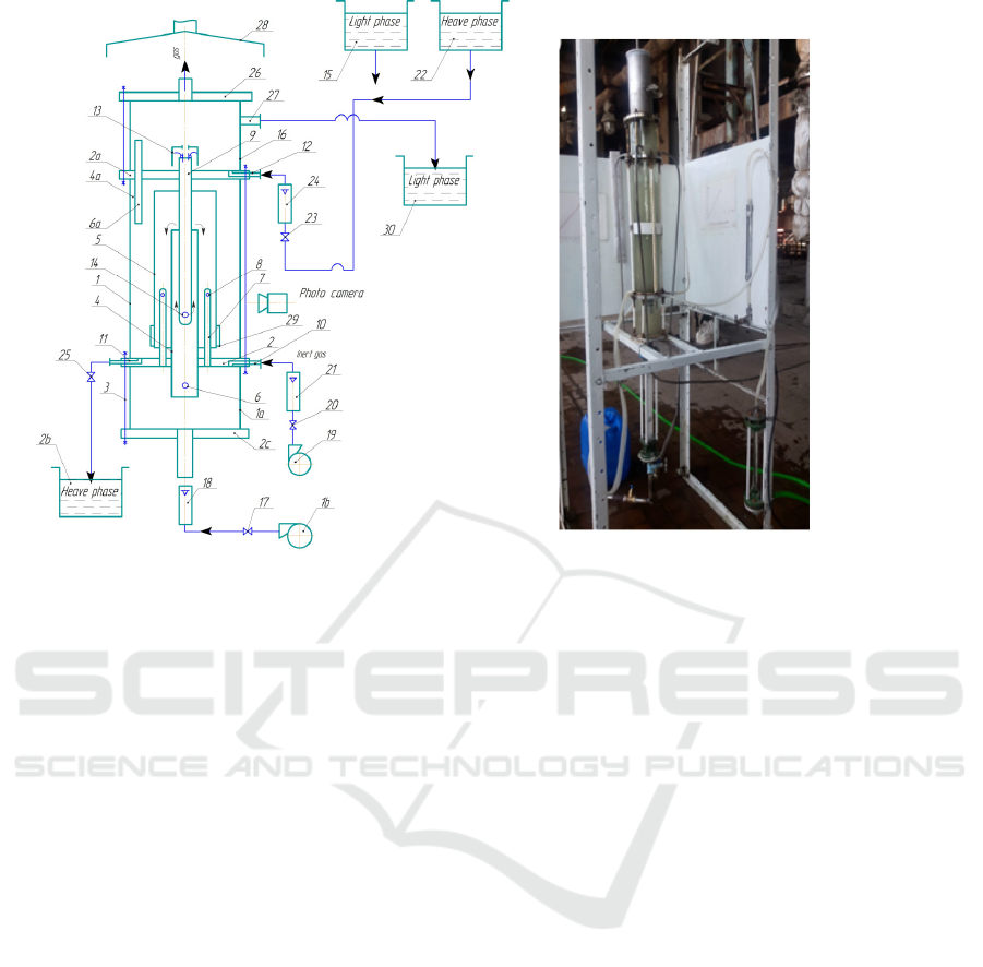
Fi
g
ure 1: Ex
p
erimental device scheme
Fi
g
ure 2: General view of the ex
p
erimental device
The entry of heavy fluid into the apparatus is
controlled by the glass pipe 1b. The hood 13 is
mounted on the top end of pipe 9 so that heavy fluid
can enter the mixing zones only in full. As the light
fluid phase moves from bottom to bottom in the
drilling rig 4, pipe 9 drops the heavy fluid flowing
through hole 14 and drives upward in the direction of
the shaft. Heavy and light fluid phases are rapidly
interspersed with gas entering the hole 6 on the drip
rig.
Mixed fluids flow through the ring to the ring
between 4 and 5 pipes, where the pipe 7 is further
mixed with the gas coming out of the hole 8. The
bottom of the pipe 5 is mounted below the pipe 7 of
the pipe 7, which ensures that the gas is supplied only
to the circular duct. Mixed fluid phases go from the
ring channel to the deposition zone of the apparatus.
This zone is formed between the glass turbine 1 and
the mixer pad 4. The video camera 28 is used to
determine the diameter of the drilling heavy phase
drops. Fiberglass 29 is mounted on Patrol 5 to prevent
leakage of heavy phase drops with light phase. The
filter holds heavy phase drops of small particles that
are difficult to sink.
As a result of heavy phase drops, homogeneous
layers are formed on the surface of the flannel 2 of the
section. The recycled heavy fluid is pumped out to
vessel 26 using valve 25 through channel 11. The
boundary separating fluid phases is maintained by the
valve 25. Light fluid and gas are released into the
upper section through hole 6a in hole 4a. There, the
gas is released from the liquefied liquid, and the light
fluid is transferred through Channel 27 to the
container 15.
Investigations into the apparatus's hydrodynamic
processes the department of acetic acid regeneration
at JSC "Ferganaazot" conducted a study on the mass
exchange and hydrodynamic processes of the
equipment used in the water extraction of butyl and
ethyl acetate liquids. The process of dissolving heavy
liquids in the apparatus's mixing zones was
investigated using model fluids.
Several experimental investigations have
established the mechanism of pneumatic grinding of
heavy fluid into droplets in heterogeneous L-L-G-
system settings (Alimatov, Sokolov, Salimov, and
Khursanov, 2001; Ermakov, 1986; Ivanenk, 1982;
Sokolov, Metkin, and Domansky, 1968; Shinar and
Charch, 1960).
Unlike other mixing techniques, pneumatic
mixing of unstable liquids results in the formation of
a multi-dispersed system of granular droplets. The
size of the inter-phase contact surfaces determines the
size of the droplets in this multi-disperse system. The
size of the entire phase determines how these droplets
are scattered. The value of drop sizes influences the
extraction process's rate of mass transfer inside the
phase separation phase and, second, the phase
separation of the droplets in the deposition zones at
each stage of the apparatus.
ICHELS 2024 - The International Conference on Humanities Education, Law, and Social Science
792

The mass transfer mechanism is difficult to
theoretically justify in a multi-dispersed system of
drops. A single-dispersive particle size calculation
has replaced a multi-disperse system as a result of
multiple studies to streamline the computation. This
allows the mass transfer coefficient to be calculated
in comparison to a single drop (Moryakov, Nikolaev,
and Nikolaev, 1973).
Gal-or proposes a theory that can theoretically
determine the mean inter-phase contact surfaces of
droplets in a multi-disperse system by calculating
droplet-to-mass mass transfer coefficients based on
the transition from a multi-disperse system to a
single-disperse system.
Comparative phase surfaces F_(v.s) are defined as
follows, depending on the droplet diameter [3,9,10].
φ = V
d
/ (V
g
+V
d
)
(1)
Where V-mixing zone volume, m
3
. φ-the fraction
of the dispersion phase in the total phase, V
g
and V
d
-
Consumption of gross and dispersion phases m
3
/h,
d
v.s
-аverage volume of drop - surface diameter, m
The particular surface area of the droplet created
in the columns of periodic drilling rigs can be
computed using the following formula (Sokolov and
Reshanov, 1960).
(2)
where γ
d
- is the kinematic viscosity of the
dispersion phase,
According to Metkin's experimental research, the
surface of the relative phase interconnectivity of
droplets dispersed throughout a multi-step pipe
extractor's mixing zone looks like this [11].
(3)
Where l- length of the pipe, m
d
tube
-diameter of the pipe, m
An optimal mixer extractor near these devices can
use equation (3) derived from research in the tubular
circulation mixing extractor (Alimatov, Sadullaev,
Karimov, and Khursanov, 2019). Professor B.A.
Alimatov looks into the fact that the extracted fluids
in the multistage bubble extractor's mixing zones are
in direct flow (Sokolov and Yablokova, 1986;
Sokolov and Domansky, 1976; Metkin, 1968;
Alimatov, 2003; Alimatov, 1980).
The multistage bubble extractor, an
experimental apparatus created by B.A. Alimatov,
was used for the investigation (Sokolov and
Yablokova, 1986; Sokolov and Domansky, 1976;
Metkin, 1968; Alimatov, 2003; Alimatov, 1980).
The goal of the study was to determine the
average volume-surface diameter of droplets'
computational equation, which would be utilized to
compute the mass transfer processes in the barbed
extractor. The following formula can be used to
calculate a drop's average volume-surface diameter:
(4)
Where d
max
-is the maximum diameter of the drop
in emulsion, m
а and β - constant
According to recommendation [7], β = 0.725, and
"a" can be found in the following equation:
(5)
where d
50
–drop diameter to 50% relative volume.
In turn;
(6)
Where d
90
and d
10
- drop diameter of 90% and
10%.
It is advised to use the following empirical
formula to determine the surface diameter of droplets
in experimental studies: fluid surface tension, volume
fraction dispersion φ, gas velocity wγ, average
stirring time tav., and mass phase viscosity μg.
(7)
The structural design of the bubble extractor
studied by B.A. Alimatov is based on the mixing of
fluid phases in the drilling rig only. The bubble
extractor we investigate [2] has an additional mixing
zone, with additional phase mixing in the fluid
phases, such as in the bubble seal and the outer ring
channel. The advantage of this extractor is that it
operates in an intensive mode due to the high mixing
time. This, in turn, requires research into the
distribution and size distribution of drops in mixing
zones.
Therefore, the experimental design of the new
bubble extractor unit was investigated and the
distribution and dispersion of dispersion phase
droplets by the size of the apparatus dispersed from
the mixing zones (Sokolov and Yablokova, 1986;
Sokolov and Domansky, 1976; Metkin, 1968;
Alimatov, 2003; Alimatov, 1980).
Drainage and Distribution of Heavy Liquids by Mixing Fluid Phases with Inert Gas in Bubble Extractor
793
Experimental researches were carried out on the
experimental device of the bubble extractor installed
in the shop of SA and SKR of JSC "Ferganaazot".
Video cameras were filmed and filmed during the
extrusion washing of butyl acetate and ethyl acetate
fluids in the experimental device. However, due to the
same color of water and butyl acetate and ethyl
acetate liquids, it was difficult to determine the size
of the droplets using photographs. Therefore, model
fluids were used. A mixture of carbon dioxide +
benzene was obtained as a heavy liquid. Mixture
density was calculated at rd=1120kg/m
3
. Density was
determined using aisometer under laboratory
conditions. The physical and chemical properties of
industrial and model fluids are shown in Table 1. The
selected mixture was colored with a coloring powder
"Ditizon" (1,5-diphenylthiocorbazone S12N2N4S) to
give a clear picture in video and pictures.
Dimensions of the mixing zones of the dredge
extruder unit are as follows: 1. Dimensions of internal
mixing zones: internal diameter d = 0.032m, outer
diameter d
o
= 0.036m, height H
0
= 0.5m. Exterior
mixing zone sizes: inner diameter of glass tube D
i
=
0056m, outer diameter D
o
= 0064m, height H =
0.335m. Experimental device glass pipe internal
diameter - 104 mm;
The experiments were conducted in the following
order. In the first phase of the experiment, inert gas
was supplied to the internal and external mixing
zones of the apparatus by means of the gas supply
holes. The size of the hole for gas injection into the
internal mixing zone is d
0
= 1.5mm, and the hole
extending to the outside mixing zone is d
1
= 1mm.The
apparatus was transferred to the unit at a constant
cost, with Q
h
= 0.23 m
3
/h. In this fluid flow, the fluid
velocity in the internal mixing zone was w
l
и
= 0.051
m/s, and in the external mixing zone, w
с
o
= 0.026 m/s.
Gas was transferred to the mixing zones at constant
fluid rates at values Q
g
=0.55; 0.65; 0.75m
3
/h.
According to these gas consumption, the gas
velocities in the internal mixing zone w
g
i
=0.03; 0.06;
0.09 m/s and in the external mixing zone w
g
o
= 0.08;
0.0803; 0.805; are converted The mixing time was
t
av
= 22 seconds. The cost of the gas cushion in the gas
distribution unit of the unit, according to the gas
consumption, was h=15; 20; 37 mm. The ratio of light
and heavy fluids supplied to the apparatus was chosen
at a constant rate of 3/1 for each experiment. The
process of mixing liquid phases with gas and
dissolving heavy liquid into droplets was filmed and
filmed using a Canon EOS 700 D camera. A 0.8 mm
diameter wire was fitted to the outside mixing zone
for comparison of droplet sizes. Five photographs
were taken to determine the droplet size at each gas
velocity. In the second phase of the experiment, the
total phase consumption was changed to a constant
value Q
с
= 0.31 m
3
/h. The fluid velocities in the
internal and external mixing zones were w
с
i
= 0.11m /
sec and w
с
т
= 0.035m / sec. At these constant fluid
velocities, the gas flow to the mixing zones was
repeated in the first phase of the experiments.
Gas was supplied at Q
g
=0.55; 0.65; 0.75m
3
/hour.
In accordance with this gas consumption, the
velocities in the internal mixing zone w
г
и
= 0.03; 0.06;
0.09 m/s and in the external mixing zone w
г
т
= 0.08;
0.0803; 0.805; are converted. The mixing time was t
av
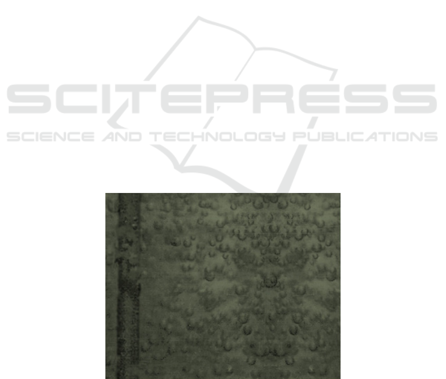
= 14 seconds. In both experiments, the droplet size for
the selected profiles was determined by photographs.
An example of the photographs is shown in Figure 3.
Figure 3: Method for determining the dispersion phase droplet size.
ICHELS 2024 - The International Conference on Humanities Education, Law, and Social Science
794
For each stage of the experiments, the size of 400
÷ 600 drops was determined from the photographs,
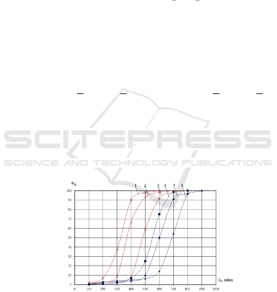
and the percentage values were found at intervals.
The regression equations were processed using the
ECM, and the droplet distribution diagrams were
constructed (Figure 3). The physical and chemical
properties of liquids are shown in Table 1.
The next task is to produce an equation that
calculates the average volume-surface diameter of
droplets used to calculate the mass transfer processes
in the proposed biodegradable extractor based on the
results obtained.
The results of the experiments determine the
average volume-surface diameter of the main
constituents by equations 4,5,6 (Sokolov and
Yablokova, 1986; Sokolov and Domansky, 1976;
Metkin, 1968; Alimatov, 2003; Alimatov, 1980).
.
Where d
90
and d
10
,90% and 10% for 1 line in
Figure 4
d
90
= 400 mkm , d
5о
=330mkm , d
10
=
240mkm.
When these values are presented in equation
(6), we get:
And d
max
= 491mkm the distribution parameter is
defined
Based on this, d
v.s
is defined;
All calculations based on the results of the
experiments are shown in Table 2.
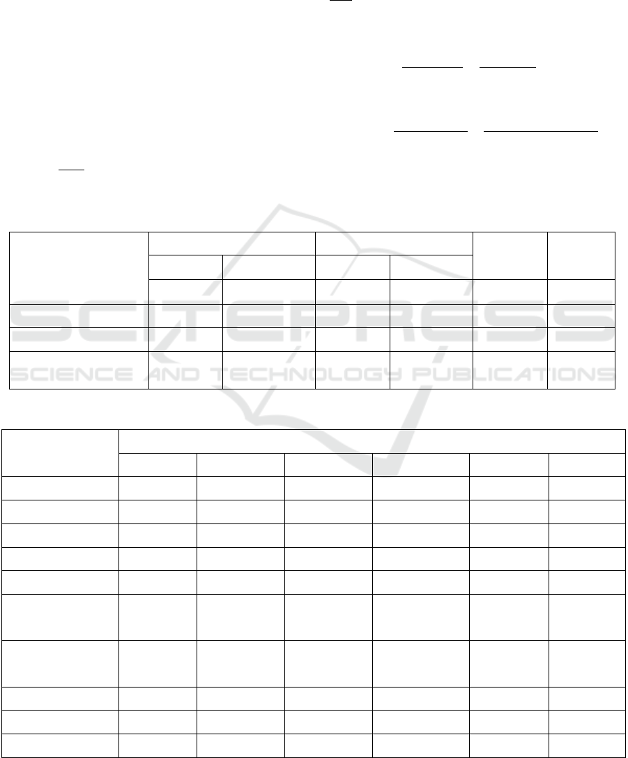
Table 1: Physic and chemical properties of substances
Fluids
Continuous phase Dispersion phase
σ
ϕ
ρ
с
μ
с
ρ
д
μ
д
kg / m
3
⋅ 10
-3
Pa⋅s
kg / m
3
⋅ 10
-3
Pa⋅s
N/m -
Butyl acetate -water 880 0,685 1000 1,00 0,0248 0,25
Ethyl acetate-water 888 0,423 1000 1,00 0,024 0,25
Water-four-chlorine
carbon + benzene
1000 1,00 1120 0,72 0,073 0,25
Table 2: the results of the experiments
Parameters
Line numberin Figure 5
1 2 3 4 5 6
d
90
, mkm 400 450 575 635 690 784
d
50
, mkm 330 380 490 575 600 685
d
10
, mkm 240 300 410 480 510 580
d
max
, mkm 491 600 735 702 840 1175
А 0,48 0,59 0,68 0,22 0,4 0,49
D
v.s
,mkm
(exper)
317 362 413 561 576 603
d
v.s
,mkm
(theore)
357 375 396 486 523 545
d
v.s
error on % 10 2 4 13,3 9,2 9,6
F
vol
(exper), м
2
473 414 363 267 260 248
F
vol
(theore),м
2
420 400 378 308 286 275
Drainage and Distribution of Heavy Liquids by Mixing Fluid Phases with Inert Gas in Bubble Extractor
795
3 RESULTS AND DISCUSSION
The theoretical study on application of the
recommended formula for calculating the total
surface diameter of crushed drops in the bubble
extractor, created by Professor B.A. Alimatov [13], to
the bubble extractor we investigate. In the apparatus
examined, the gas is distributed inside and outside the
mixing zones. The liquids are mixed in the internal
mixing zone with the gas velocity
and then flow
into the external mixing zone, further mixing with the
gas velocity
. As a result, the time of mixing and
stopping of fluid phases in these zones increases and
the size of heavy phase drops decreases. Experiments
confirmed this.
Therefore, formula 7 includes the arithmetic mean
and constant multiplier of gas velocities in the
internal and external mixing zones.
The formula is as follows.
(8)
Using this formula, the total surface diameter of
the droplets was determined.
For line 1.
σ=0,073n/m, t
av
=22sec,
μ
g
=0,001Pac, φ=0,25.
=3,3·10
-
5
(0,132)/(0,00122)=357mkm.
For the other lines, the surface surface diameters
of droplets were determined. The results of the
calculations are shown in Table 2. As can be seen
from the table, the percentage of error between the
drops and the experimental values of the droplets
calculated using the proposed formula is 2 ÷ 13.5%.
t
av
=22sec
t
av
=14sec
The resulting regression equations are as follows.
1.y = 0,0002x
2
+ 0,3619x - 43,1 R² = 0,9915
2.y = 0,0002x
2
+ 0,2699x - 38,486 R² = 0,9985
3.y = 0,0001x
2
+ 0,0834x - 18,627 R² = 0,9812
4. y = 0,0002x
2
- 0,0514x - 0,6393 R² = 0,9751
5. y = 0,0002x
2
- 0,0272x - 2,2381 R² = 0,9961
6. y = 0,0003x
2
- 0,1474x + 15,838 R² =
0,9842
A graph was constructed to compare the
experimental and theoretical values of the surface
diameters of the drops (Figure 5).
Figure 4: Distribution chart of dimensions.
ICHELS 2024 - The International Conference on Humanities Education, Law, and Social Science
796
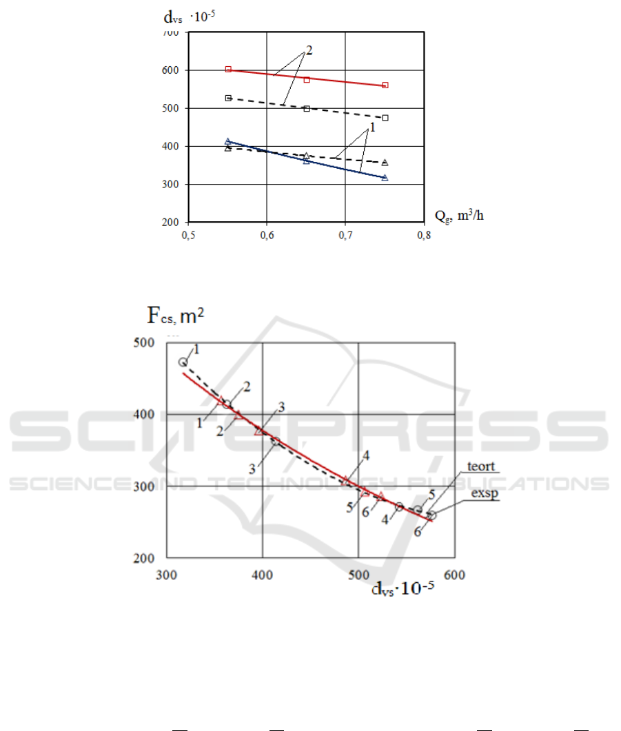
t
av
=22s; 2. t
av
=14s.
Figure 5: Graph of changes in volume of surface drops depending on gas consumption (comparative graph).
Figure 6: Graph of change of inter-phase relative surface depending on the surface surface diameter of the droplet
(comparative graph)
Using the aforementioned formula 1, the
experimental and theoretical drops of the droplets
were determined and the values of the comparative
phase surfaces depending on the volume surface
diameters shown in Table 2 and a comparative graph
were constructed.
t
av
=22sec
t
av
=14sec
The regression equations of the experimental and theoretical values were obtained.
Experimental: y = 0,0018x
2
- 2,4665x + 1067,7 R² = 0,9994
Theoretical: y = 0,0018x
2
- 2,3598x + 1036,4 R² = 0,9999
Drainage and Distribution of Heavy Liquids by Mixing Fluid Phases with Inert Gas in Bubble Extractor
797

4 CONCLUSION
The process of dissipating heavy liquid into droplets
by mixing fluid phases with inert gas was performed
on the experimental device of the dredge extractor.
Depending on the mixing time at the constant phase
velocity values, the distribution of the droplets on
different gas velocity values by grinding and size was
determined by experiments. The regression equations
were processed using the computer.
Based on the results of the experimental studies,
the total surface diameters of the droplets were
determined. A formula for calculating the total
surface diameter of droplets, which is important for
the calculation of mass transfer processes, depending
on the physical and chemical properties of liquids,
was proposed, and theoretical and experimental
values were compared.The calculations carried out
completely confirmed the proposed formula. As a
result of the research, it was possible to determine the
surface surface diameter of the dispersion phase drop
and the relative phase contact surfaces, which is one
of the key determinants of the efficiency of the
proposed bubble extractor.
REFERENCES
Alimato, B. A., Sokolov, V. N., Sadullaev, H. M., &
Karimov, I. T. (1990). Multistage bubbling extractor.
A.S. No. 1607859 (USSR), BI No. 43.
Alimatov, B. A. (1980). Multistage bubbling extractor. No.
751409 (USSR), BI No. 28.
Alimatov, B. A. (2003). Development of scientific and
technical foundations for the design of liquid extractors
with pneumatic mixing. Diss ... Ph.D. Toshkent:
Tashkent State Technical University.-270s.
Alimatov, B. A., Sokolov, V. N., Salimov, Z. C., &
Khursanov, B. Zh. (2001). Investigation of the
distribution of droplets by size in a multistage bubbling
extractor. Scientific-technical. Zhurn. FerPI. Ferghana,
70-73.
Alimatov, B. A., Sadullaev, Kh. M., Karimov, I. T., &
Khursanov, B. Zh. (2019). Methods and design and
design of equipment for processing complex
heterogeneous liquid-gas-liquid systems. Monograph.
Belgorod: BSTU.-191s.
Ermakov, S. B. (1986). Multistage gas-lifting apparatus for
washing polymers. Diss ... Ph.D. Leningrad:
im.Lensoviet.
Frolov, Y. G. (1982). Course of colloid chemistry (Surface
phenomena and dispersed systems). M.: Chemistry.
Ivanenk, A. Yu. (1982). Hydrodynamics and mass transfer
by bubbling mixing - slop extractor. Diss ... Ph.D.
Leningrad: LTI named after Lensovet.
Metkin, V.P. (1968). The study of pneumodispersion and
mass transfer by a bubble tubular extractor. Diss ...
Ph.D. Lensoviet.-182s.
Moryakov, V. S., Nikolaev, N. A., & Nikolaev, A. M.
(1973). The effect of droplet size distribution on mass
transfer in polydisperse systems. Izv. Universities.
Chemical technology, 16(10), 1580-1583.
Shinar, R., & Charch, J. M. (1960). Statistical theory of
turbulence in predicting particle size in agitated
dispersions. Ind. Eng. Chem., 52(3), 253-256.
Sokolov, V. N., & Domansky, I. V. (1976). Gas-liquid
reactors, L.: Engineering.-216.
Sokolov, V. N., Metkin, V. P., & Domansky, I. V. (1968).
Pneumodispersion of immiscible liquids in a tubular
bubble extractor. Housing and communal services, 41,
1029-1036.
Sokolov, V. N., & Reshanov, A. S. (1960). On the effect of
time on the fragmentation of droplets in a stream
turbulized by bubbling gas. ZhPKh, 33, 1068-1075.
Sokolov, V. N., & Yablokova, M. A. (1986). Devices for
dispersing immiscible liquids. A.S. No. 1258465
(USSR), BI No. 35.
ICHELS 2024 - The International Conference on Humanities Education, Law, and Social Science
798
