
Expectation-Based Integration Testing of Unidirectional Interactions in
Component-Based Software Systems
Nils Wild
a
, Horst Lichter
b
and Constantin Mensendiek
c
Research Group Software Construction, RWTH Aachen University, Ahornstraße 55, Aachen, Germany
Keywords:
Software Testing, Test Automation, Software Quality Assurance, Integration Testing, Component-Based
Software Engineering.
Abstract:
Effective and efficient testing of complex component-based software systems is difficult. Unit test cases that
test isolated components are focused and efficient but ineffective in detecting integration faults. Integration
test cases, on the other hand, are hard to develop and maintain. With the UTBI meta-model and InterACt,
a concept and tool implementation was developed to extract expectations towards other components from
unit test cases and reuse unit tests to automate the verification of those expectations. However, the approach
is limited to request-response interactions implicitly defined by mock interactions. This paper presents an
extension to specify and verify expectations toward unidirectional interactions not encoded in the unit test
cases. For example, if the recipient of the reaction to an interaction stimulus is not the same component that
sent the stimulus in the first place.
1 INTRODUCTION
Component-based software architectures emphasize
the separation of concerns with respect to the wide-
ranging functionality available throughout a given
software system. Such architectures have proven ben-
eficial to cope with team organization and rapidly
changing requirements (Vitharana, 2003). They also
allow for the composition of components to create tai-
lored systems for the needs of individual customers
(Atkinson et al., 2000). Customer requirements are
usually fulfilled by multiple services that interact with
each other through a well-defined API (Crnkovic and
Larsson, 2002). While unit testing focuses on testing
the functionality of single components, integration
testing focuses on these interactions. Testing these
interactions is challenging and requires additional ef-
fort (Jaffar-ur Rehman et al., 2007). This is because
certain faults can only be detected on the integration
level, such as interface faults, interpretation faults,
and miscoded call faults, resulting from misconcep-
tions about an interface (Leung and White, 1990). To
minimize the effort required to achieve a decent test
coverage on the integration level, we propose an inte-
a
https://orcid.org/0009-0003-6077-8535
b
https://orcid.org/0000-0002-3440-1238
c
https://orcid.org/0000-0002-7081-8065
gration testing approach that reuses test data and data
flow information that can be observed during unit test
execution and property-based specifications of the ex-
pectations towards the system under test. The thereby
generated test cases are sensitive to integration faults
and automatically adapt to behavioral and architec-
tural changes of the system under test.
2 PROBLEM STATEMENT AND
OUTLINE
Integrating large component-based systems is still
challenging, especially if the integration should start
as early as possible (Jaffar-ur Rehman et al., 2007;
Shashank et al., 2010). Special integration tests are
required to check the integration of a system.
According to ISO 24765, integration testing eval-
uates the interactions between the components of a
software system (IEEE, 2017). If we transfer this
statement to component-based systems that interact
using messages, such a system is correctly integrated
if, for every interaction stimulus message received by
a system component, there are correct reaction mes-
sages triggered.
A reaction message can either be perceived by the
component that initiated the interaction or by another
202
Wild, N., Lichter, H. and Mensendiek, C.
Expectation-Based Integration Testing of Unidirectional Interactions in Component-Based Software Systems.
DOI: 10.5220/0012725900003687
Paper published under CC license (CC BY-NC-ND 4.0)
In Proceedings of the 19th International Conference on Evaluation of Novel Approaches to Software Engineering (ENASE 2024), pages 202-213
ISBN: 978-989-758-696-5; ISSN: 2184-4895
Proceedings Copyright © 2024 by SCITEPRESS – Science and Technology Publications, Lda.

component of the system or by an external system.
The former reaction message is thus considered a re-
sponse message as it is expected as a response to the
interaction stimulus message. We consider the latter
an event message, notifying other components about
the interaction and, eventually, its effects. Other com-
ponents’ expectations towards this message determine
whether or not a reaction message is correct.
Our former work presents a new integration test
approach for component-based systems that reuses
the existing unit test suites to derive interaction ex-
pectations for each component (Wild and Lichter,
2023b). These are used to evaluate the response mes-
sages that are triggered within the system. With an
application-specific meta-model (UTBI-MM), we set
the conceptual foundation to derive such interaction
expectations, to retrieve indicators for the integrata-
bility of component-based systems and derive test
cases that verify those interaction expectations. The
application-specific tool (InterACt) implements that
concept as a proof-of-concept prototype (Wild and
Lichter, 2023a).
However, expectations towards event messages
that are not perceived by the component that received
the stimulus message are not considered and included
in the generated integration tests. Thus, in this paper,
we will answer the following research questions:
Q1. How can expectations towards event messages
be expressed and formalized?
Q2. Can such expectations be verified given the in-
formation that can be captured during unit test
execution?
The paper is structured as follows: Section 3 de-
scribes a simple component-based system that will be
used as an example throughout the paper. Section 4
briefly presents our approach to test component inter-
actions based on unit tests. In Section 5, we introduce
the conceptual foundations, namely system properties
and system property expectations, needed to specify
and verify expectations toward unidirectional interac-
tions not encoded in the unit test cases. Section 6 de-
scribes how the extended concepts were implemented
in InterACt. Section 7 discusses the results obtained
and describes the presented testing approach’s advan-
tages and limitations. Section8 contains the related
work. The planned next steps and future work con-
clude this paper in Section 9.
3 AN EXEMPLARY SYSTEM
The exemplary component-based system described in
this section will be used to explain the concepts in-
troduced in this paper
1
. The system consists of the
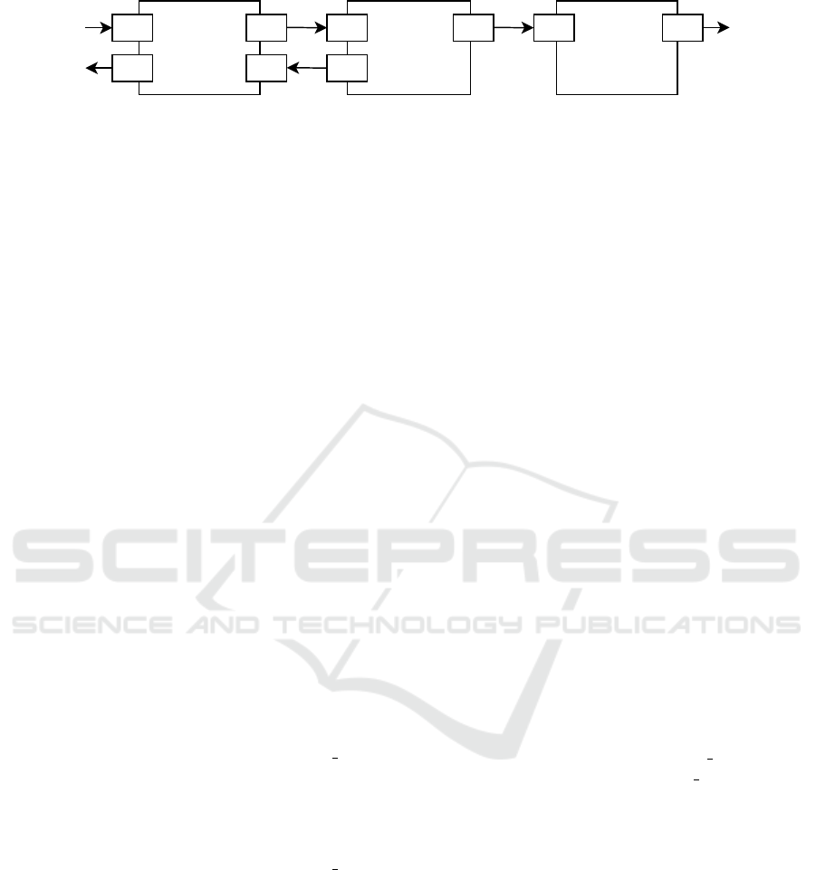
following three components (see Figure 1):
• The Authoring component supports authors to
manage articles and publish them to the News
component.
• The News component stores all published articles
and serves them to the readers. It also informs
the Notification component whenever there are
new articles or updates to existing ones.
• The Notification component generates notifi-
cations for any changes that it is informed about
and publishes them to a public interface that third-
party clients can subscribe to.
A unit test suite exists to test each component in
isolation using the needed mock components. Each
unit test case represents one scenario of how other
components are expected to interact with the compo-
nent under test. One unit test case (UTC) for each
component is explained in more detail:
• UTC1: The Authoring component is stimulated
with a message M1 on its interface I1 to publish
an article. The component reacts with a message
M2 on its interface I2 that is sent to a mock repre-
senting the News component. This mock responds
with a success message M3 that is received by the
interface I3 of the Authoring component. The
article is marked as published and the Authoring
component responds with a success message M4
on its interface I4.
• UTC2: The News component is stimulated with a
message M5 on its interface I5 to publish a new
article. The component reacts with a message M6
on an interface I6 that is sent to a mock repre-
senting the Notification component. The arti-
cle gets stored and the component responds with
a success message M7 on its interface I7.
• UTC3: The Notification component is stimu-
lated with a message M8 on its interface I8. The
component reacts with a message M9 that is sent
by its interface I9.
4 TESTING COMPONENT
INTERACTIONS BASED ON
UNIT TESTS
In our former work, we presented a new approach to
integration testing of component-based systems that
1
The code of this system is available on GitHub https:
//github.com/NilsWild/InterACt
Expectation-Based Integration Testing of Unidirectional Interactions in Component-Based Software Systems
203
Authoring News Notification
I1
I4
I2
I3
I5
I7
I6 I8 I9
Figure 1: Architecture of the exemplary system.
reuses the existing unit tests to derive so-called inter-
action expectations and check the integration of all
components by verifying that a subset of the other
components can fulfill those expectations. In the fol-
lowing, we recapitulate the most central concepts of
this approach. A detailed description can be found in
(Wild and Lichter, 2023b).
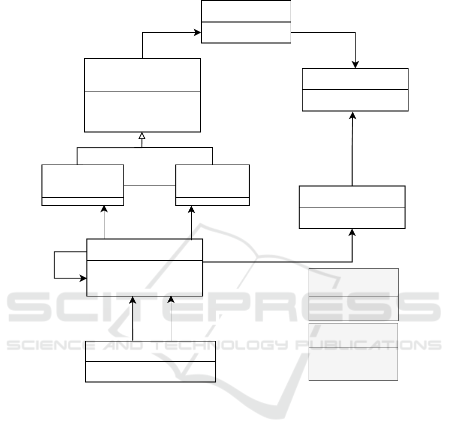
4.1 The UTBI Meta-Model
The UTBI meta-model (see Figure 2) defines all en-
tities and relationships to model architectural and in-
teraction information needed to test the integration of
components based on information gathered by exist-
ing unit test suites.
Components are the core elements. They com-
municate using Messages (Msg) through Incoming-
Interfaces (InIF) and OutgoingInterfaces (OutIF). An
incoming interface is bound to (boundTo) an arbi-
trary number of outgoing interfaces and vice versa.
For each component, the respective unit test cases are
modeled as well.
Once a test case of a component under test (CUT)
gets executed, a sequence of messages (linked to-
gether by the next relationship) is triggered by the test
case. We distinguish three types of messages:
• A stimulus message (STIMULUS) is a message
received by the CUT from the test case.
• A component response message (COMP RESP)
is a message sent by the CUT back to the test
case or to other components (those components
are called the CUTs environment and are usually
represented by mocks).
• An environment response message (ENV RESP)
is a message sent by a component of the CUTs
environment back to the CUT as a reaction to a
received component response message.
This information can be extracted by the tool In-
terACt (Wild and Lichter, 2023a) during the execu-
tion of the unit test suite of one component to create
an instance of the UTBI meta-model, also referred to
as UTBI-MM component model. By binding the inter-
faces in all UTBI-MM component models, the Inter-
ACt creates the UTBI-MM system model.
4.2 Interaction Expectations
An interaction expectation describes an expectation of
a component towards an interaction with other com-
ponents. Interaction expectations are derived based
on the information captured in the UTBI-MM com-
ponent models. This can be explained best by an ex-
ample.
Let us look at the test case UTC1 of our exem-
plary system. The Authoring component sends a
component response message M2 to the mock repre-
senting the component’s environment. This mock re-
sponds with the environment response message M3.
This yields the following interaction expectation of
the Authoring component: there must be one or mul-
tiple interacting components to react to the message
M2 with a message that can replace M3 in the test
case UTC1.
In general, a message M
r
can replace a mocked
message M
m
if message M
m
can be exchanged with
M
r
in the unit test case UTC such that UTC still suc-
ceeds.
In our example, the Authoring component
expects to receive an environment response message
(a success message) on interface I3 when it publishes
an article via interface I2. Formally spoken, an inter-
action expectation ie is an ordered pair of messages:
ie = (m
s
, m
r
) | m
s
, m
r
∈ Msg ∧
type(m
s
) = COMP RESP ∧
type(m
r
) = ENV RESP
stimulus(ie) = π
1
(ie)
reaction(ie) = π
2
(ie)
Please note that the first message of an interac-
tion expectation is called expectation stimulus, and
the second is called expectation reaction. In our ex-
ample, (M2, M3) is one of the interaction expecta-
tions of the Authoring component.
4.3 Interaction Paths
To check if the system could fulfill an interaction
expectation, interaction paths from the expectation
stimulus message to the corresponding reaction mes-
sage must be found in the UTBI-MM system model.
Each path represents one interaction scenario given
ENASE 2024 - 19th International Conference on Evaluation of Novel Approaches to Software Engineering
204
Component
+ name: String
provided by
<<abstract>>
Interface
+ visibility: AccessType
+ protocolName: String
+ protocolData: String
AbstractTestCase
+ name: String
derived from
TestCase
+ values: String
Message
+ payload: String
+ type: MsgType
next
Incoming
Interface
bound to Outgoing
Interface
<<enumeration>>
MsgType
STIMULUS
COMP_RESP
ENV_RESP
<<enumeration>>
AccessType
PRIVATE
PUBLIC
0..*
1
tested by
1
0..*
0..*
0..*
0..*
1
triggered by
0..*
1
0..*
11
interaction
stimulus
interaction
reaction
Interaction Expectation
+ verified: Boolean
1
1
1
received by
0..*
send by
0..*
Figure 2: Elements of the UTBI Meta-Model.
by the set of scenarios represented by the individual
unit tests along that path. In our example, at least one
interaction path between M2 and M3 must be found.
To this end, all messages and interfaces and their
relations must be considered. These elements can
be extracted from the property graph representation
(UT BI-MM-PG) of the UTBI-MM system model,
which we already introduced in (Wild and Lichter,
2023b) and which is defined as follows:
Given finite sets of labels L - corresponding to
the meta-model’s entities and relations - and property
keys K - the attribute names of the meta-models el-
ements - and an infinite set of property values V , a
UTBI-MM system model can be defined by a prop-
erty graph UT BI-MM-PG over (L,K , V ), which is a
structure (N , E, ρ, λ, ν), such that
• N and E are finite sets of node and edge identi-
fiers,
• ρ : E −→ N × N is a total function that associates
a pair of node identifiers to each edge identifier,
• λ : N ∪ E −→ L is a total function that associates
each node and edge with a label from L and
• ν : (N ∪ E)×K −→ V is a partial function that as-
sociates nodes and edges a value for each property
key.
Based on the UTBI-MM-PG graph, we de-
fine a much simpler directed interaction graph
UTBI-MM-IG = (N
′
, E
′
) as such:
N
′
= {n ∈ N |λ(n) ∈ {Msg, OutIF, InIF}}
E
′
= {(n, m)|(m, n) ∈ E ∧ λ((m, n)) = recBy ∨
(n, m) ∈ E ∧λ((n, m)) ∈ {sentBy, boundTo, next}}
The graph UTBI-MM-IG contains only message
and interface nodes and all edges between those
Expectation-Based Integration Testing of Unidirectional Interactions in Component-Based Software Systems
205

nodes. However, the direction of the received by
edges is inverted to represent the message flow direc-
tion in the system. Finding interaction paths in UTBI-
MM-IG is a path-finding problem from the inter-
action stimulus message to the interaction response
message over UTBI-IG, in the given example from
M2 to M3. If one or multiple paths can be found,
they are used to verify the interaction expectation. If
none is found, the interaction expectation can not be
verified.
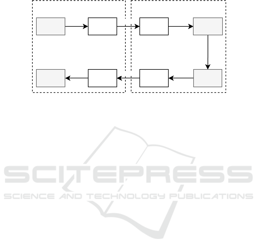
An excerpt of the resulting UTBI-MM-IG for our
exemplary system, including the unit test cases UTC1
and UTC2, is shown in Figure 3. M2 is sent by I2 in
UTC1, I2 is bound to I5. In UTC2, M5 was received
by I5. The receiving component reacted to M5 with
M7. M7 was sent by I7, which is bound to I3. Via I3,
the message M3 was received in UTC1 as the mocked
response to M2.
An interaction path for an interaction expectation
ip
ie
is an ordered list of message-interface pairs. The
message of the first pair is the interaction stimulus
message; the one of the last pair is the environment
response message received in the unit test as a reac-
tion to the interaction stimulus. As the interface of
the first pair must be an outgoing one and the one of
the last pair an incoming interface, the size of the list
must be even. Further, the ordered list represents a
chain of connected messages representing a possible
system data flow. An interaction expectation is
defined as follows:
ip
ie
= ((m
1
, i
1
)..(m
n
, i
n
)) with
n%2 = 0
m
1
= stimulus(ie) ∧
∀(m
j
, i
j
) ∈ ip
ie
|
isBoundTo(i
j
, i
j+1
)∨
isNext(m
j
, m
j+1
) if j < n
isSentBy(m
j
, i
j
) if j%2 = 1
isReceivedBy(m
j
, i
j
) if j%2 = 0
In our example, the list ((M2, I2), (M5, I5), (M7,
I7), (M3, I3)) of message-interface pairs is an interac-
tion path for the interaction expectation (M2, M3) of
the Authoring component.
4.4 Verification of Interaction
Expectations
To verify an interaction expectation, so-called inter-
action test cases are generated. An interaction test
case is a variant of an existing unit test case where the
stimulus and environment response messages are ex-
changed with component response messages of com-
ponents along an interaction path, ultimately simulat-
ing and testing the integration along that path.
Based on our example interaction path ip
(M2,M3)
=
((M2, I2), (M5, I5), (M7, I7), (M3, I3)), two interac-
tion test cases (ITC) are generated:
• ITC2 is a variant of UTC2 of the News compo-
nent, where the original stimulus message M5 re-
ceived by interface I5 is replaced by message M2.
This is permitted because interface I2 is bound to
interface I5. The News component will respond to
M2 with a new message M7’ sent by interface I7.
• ITC1 is a variant of UTC1 of the Authoring
component. There, the environment response
message M3, originally sent by the mock of the
News component, is replaced by M7’. So, the
mocked environment response message in UTC1
is replaced with the actual response message of
the News component.
If all interaction test cases generated for at least
one interaction path associated with an interaction ex-
pectation are successful, the interaction expectation is
verified, as all tests with exchanged messages do not
fail, thus simulating the integration. In our example,
the mocked message M3 can be replaced by M7’, thus
verifying the interaction expectation (M2, M3).
5 TESTING SYSTEM
PROPERTIES BASED ON UNIT
TESTS
However, expectations towards reaction messages in
unidirectional interactions that are not perceived by
the component that sends the interaction stimulus are
not part of the unit tests as these reactions are irrel-
evant to the component that initiated the interaction.
Nevertheless, the system is expected to react accord-
ing to the specification. Thus, a way to express those
expectations and verify that the system fulfills them
is needed. To this end, in the following, we introduce
the concepts of system property and property expec-
tation.
5.1 System Properties and System
Property Expectations
Usually, requirements specify system properties
independent of implementation details. In the context
of our example, such a system property could be
described as follows:
News feed consumers should get notified when an
article is published. [SP]
ENASE 2024 - 19th International Conference on Evaluation of Novel Approaches to Software Engineering
206
sentBy
M2
boundTo
I2
recieved
I5
next
M5
sentBy
M7
boundTo
I7
received
I3M3
UTC1 UTC2
Figure 3: Excerpt of the interaction graph of the exemplary system.
According to Fink and Bishop (Fink and
Bishop, 1997), the specification of system proper-
ties drives the testing process, which assures that
the implemented system meets the stated prop-
erties. To test a system property, a concrete
system property expectation (in short, property ex-
pectation) must be formulated on the basis of a given
property specification and the design decisions made.
In the case of component-based systems that
interact using messages, a property expectation
should define messages that comply with the system
property stimulus message. For our example system,
one property expectation (PE) could be the following:
When the article specified by message M1 is pub-
lished by receiving M1 on interface I1 of the Au-
thoring component, a notification message M9’
should be sent by the interface I9 of the Notifica-
tion component that contains the same title as the
article specified in M1 [PE]
To bridge the gap between the high-level descrip-
tion of a system property and its respective explicit
property expectation that can be used to test the sys-
tem property, we propose that the description of sys-
tem properties contains the following information:
• Interface expectations that define on which inter-
faces the property stimulus message and the prop-
erty reaction messages are expected
• A predicate to filter the property stimulus mes-
sages the property should hold for
• Assertions to verify the property by checking the
correctness of the reaction messages
For our exemplary system property (SP), a de-
scription that conforms to this could be the following:
When a publish-article message is sent to an in-
terface IE
x
(interface expectation regarding the
property stimulus message)
And this message contains a valid article to pub-
lish (predicate)
Then, a notification message should be received
via interface IE
y
(interface expectation regard-
ing the property reaction message) containing the
same article title as the one published (assertion)
Notice that the publish-article message in this de-
scription is expected to be sent to an interface instead
of being received by an interface and vice versa for
the notification message. This way, a system prop-
erty describes how the system should be used without
knowing the internal structure of the system. Thus,
the definitions of the system’s internal interfaces can
change without breaking the contract given by the
system properties as long as the interface expectations
still match with existing interfaces.
To derive the property expectation from this sys-
tem property specification, matching interfaces in the
system that would be bound to those interfaces de-
scribed by the interface expectations IE
x
and IE
y
must
be found. Next, messages received by those matched
interfaces are to be searched.
For our exemplary system, we expect a definition
for IE
x
to be given such that IE
x
matches I1 and IE
y
matches I9. Thus, M1 is a property stimulus message,
resulting in the derived property expectation PE.
5.2 Verification of System Properties
System properties are verified based on the property
expectations derived from them. The following steps
must be carried out for each system property:
Expectation-Based Integration Testing of Unidirectional Interactions in Component-Based Software Systems
207
Component
+ name: String
Interface Expectation
provided by
<<abstract>>
Interface
+ visibility: AccessType
+ protocolName: String
+ protocolData: String
AbstractTestCase
+ name: String
derived from
TestCase
+ values: String
Message
+ payload: String
+ type: MsgType
next
Incoming
Interface
bound to Outgoing
Interface
0..*
1
tested by
1
0..*
0..*
0..*
0..*
1
triggered by
0..*
1
0..*
11
interaction
stimulus
interaction
reaction
Interaction
Expectation
+ verified: Boolean
1
1
1
received by
0..*
send by
0..*
property
stimulus
property
reaction
Property
Expectation
+ verified: Boolean
1
1
1
0..*
System Property
+ predicate: String
+ assertions: String
matches0..*
0..*
derived from
1
0..*
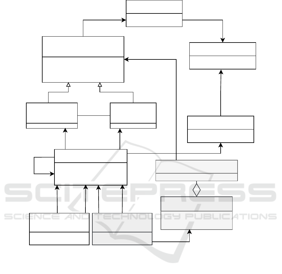
Figure 4: UTBI Meta-Model extension (added elements are highlighted in gray).
1. Resolve Interface Expectations: Interfaces match-
ing all interface expectations defined by the sys-
tem property must be found. Interfaces can match
exactly or be bound to the interfaces defined by
the interface expectations. If no matching inter-
face can be found, either the system does not pro-
vide the required functionality, or the interface ex-
ists but is not included in the UTBI-MM system
model. This case has detected a test gap or miss-
ing functionality, as the interface is not used in at
least one unit test.
2. Filter candidate messages: Based on the inter-
faces matching the interface expectation for the
property stimulus message, all messages received
by those interfaces are selected as candidates to
derive property expectations. These candidate
messages are filtered using the predicate defined
by the system property. Each resulting message
is used as a property stimulus message to a new
property expectation. If no messages remain after
the filtering, either a test gap exists as no represen-
tative of the equivalence class covering the inter-
action scenario was recorded during unit testing or
the predicate of the system property is too strong.
3. Generate and Run Interaction Tests: Interaction
tests based on the possible interaction paths are
generated and executed for each property expec-
tation.
4. Verify the System Property: For each property ex-
pectation, at least one interaction path must be
tested successfully to verify the system property.
If this holds for all derived property expectations,
the system property holds.
ENASE 2024 - 19th International Conference on Evaluation of Novel Approaches to Software Engineering
208

In our exemplary system property SP, the message
M1 is chosen as a candidate message. Assuming that
M1 passes the predicate-based filtering (it contains a
valid article to publish), M1 is used as the property
stimulus message of the derived property expectation
PE. Next, the interaction test cases are generated ac-
cordingly. Once the interaction test cases are exe-
cuted, the thereby triggered message M9’ in conjunc-
tion with M1 is evaluated to hold the system prop-
erty’s assertion (message M9’ has to contain the same
article title as message M1).
5.3 Extension of the UTBI Meta-Model
We extend the UTBI meta-model to use all new mod-
eling elements in our approach, as shown in Figure
4. A system property contains interface expectations
for the property stimulus and reaction messages. Fur-
ther, a system property defines the predicate for filter-
ing and the assertions. An interface expectation can
match with specific interfaces within the UTBI-MM
system model. A property expectation is derived from
a system property. Property expectations are modeled
similarly to interaction expectations. The only differ-
ence is that the same component might not send the
message that triggers the reaction as the one that re-
ceives the reaction message.
6 INTEGRATION INTO InterACt
InterACt implements the unit test based integration
testing concept as a JUNIT extension. It requires writ-
ing the unit test cases as parameterized tests. The pa-
rameters are the messages the CUT receives during
the test: the stimulus and the environment responses.
In addition, expected values can be provided to be
used in assertions for unit testing. For interaction test-
ing, the parameter values are exchanged, according
to the aforementioned interaction test generation pro-
cess, to simulate the integration of the CUT into the
system. The expected values are set to null, and as-
sertions relying on them are not evaluated. The CUT
must provide its state according to the tested scenario
considering the provided messages. For example, if
the unit test describes the interaction scenario: ”When
an article draft exists, it can be published,” the test
has to provision an article with the id contained in the
publishing request the CUT will receive during test
execution. We adapted some mechanisms of Inter-
ACt to implement system properties. The annotation
@SystemProperty marks those methods that provide
system properties. These methods must be parame-
terized. The parameters represent the property stimu-
lus and the property response messages. However, no
values for these parameters are defined.
The method body defines the system property and
corresponding interface expectations for the interac-
tion stimulus and reaction messages using a KOTLIN
DSL. It defines the following elements:
whenAMessage(message: Any)
with(predicate: ((message: Any)−→ Boolean))
isSentBy(interface: OutIFDefinition)
thenAMessage(message: Any)
isReceivedBy(interface: InIFDefinition)
suchThat(assertions:
((stimulus: Any, reaction: Any)−→ Unit))
The property expectation PE could thus be imple-
mented like this:
@SystemProperty
fun ‘when News Is Published News
Feed Consumers Should Get Notified‘(
Stimulus stimulus,
Reaction reaction)
{
whenAMessage(stimulus)
.with{m -> m.title != null}
.isSentBy(
PostToUrl(
"/articles/{articleId}/publish"
)
)
.theAMessage(reaction)
.isReceivedBy(AmqpQueue("news"))
.suchThat{stimulus,reaction ->
stimulus.title == reaction.title}
}
Each such system property method is executed for
three purposes:
1. System Property Discovery: For system property
discovery, each system property method is pro-
vided with null values for its parameters. The de-
fined interface expectations for the property stim-
ulus and reaction messages are created and stored
in the UTBI-MM system model, as well as a ref-
erence to the system property method. Next, In-
terACt looks for matching interfaces and selects
messages received by those interfaces for stimu-
lus filtering.
2. Stimulus Filtering: When the system property
method is executed for stimulus filtering, Inter-
ACt provides the found messages as values for
the property stimulus. Since the message param-
eter in whenAMessage(message: Any) is not
null, the predicate is evaluated. If the predi-
cate matches the message, the message is marked
for further evaluation in the UTBI-MM system
Expectation-Based Integration Testing of Unidirectional Interactions in Component-Based Software Systems
209

model. InterACt will now look for interaction
paths and generate interaction test cases to sim-
ulate the integration.
3. Property Expectation Verification: Finally, the
property expectation is verified. The re-
action messages that are obtained from the
interaction tests are provided as values for
the interaction reaction parameter of the sys-
tem property method. The assertions given
by the suchThat(assertions: ((stimulus:
Any, reaction: Any)−→ Unit)) method are
evaluated. If they succeed, the system property
expectation is verified. When each property ex-
pectation derived from the system property is ver-
ified, the property is also verified.
The results are published to InterACt so that the
current integration status of the system can be in-
spected at anytime.
7 DISCUSSION
In this section, we discuss how the interaction test re-
sults in the context of system property expectations
can be interpreted and used to detect faults. We
also discuss the advantages and limitations of our ap-
proach.
7.1 Interpretation of Interaction Test
Results
With the presented approach, the expectations to-
wards a system can be expressed as system properties.
Based on these system properties, concrete property
expectations can be derived and verified using the in-
formation extracted from executing all unit test cases.
The following applies:
• A property expectation is verified if all generated
interaction test cases have been successful for at
least one suitable interaction path.
• A property expectation is not verified if one gen-
erated interaction test case fails on each suitable
interaction path.
• A system property is verified if and only if each
derived property expectation is verified.
In other words, if all interaction paths that satisfy the
property expectation can not be successfully tested,
either the components contain defects, the unit tests
are too strict, or the unit tests do not cover the inter-
actions required to derive the correct path. Assuming
the unit test cases cover the correct path, but the sys-
tem property can not be verified, at least one of the
components contains a defect. This does not mean
that the component whose test failed contains a de-
fect, but requires further investigation by a developer
as this is an undecidable problem (AbouTrab et al.,
2012). The result of the interaction test cases is equiv-
alent to a corresponding integration test case. How-
ever, in contrast to standard integration testing, the
interaction test cases will automatically adapt to be-
havioral or architectural changes, and side effects as-
serted in the unit test cases are considered. Addition-
ally, the approach identifies unit-level test gaps, thus
encouraging early testing. These advantages and the
limitations of the approach are discussed in detail in
the next section.
7.2 Advantages and Limitations
Integration testing of complex component-based sys-
tems is challenging and requires additional effort. The
proposed approach tries to deal with some of these
challenges. It has certain advantages over traditional
integration testing but also has some limitations as it
poses some prerequisites to the components and their
unit test cases.
• Most of the advantages discussed for the original
UTBI meta-model and the unit test based integra-
tion testing process also apply to the extended ver-
sion we presented in this paper (Wild and Lichter,
2023b). By reusing the unit test information to
identify interaction paths and driving the interac-
tion tests with the test data obtained during unit
and interaction test execution, the manual effort
to do integration testing is reduced. Since the sys-
tem properties and derived property expectations
are not directly related to specific components, the
generated interaction tests adapt to system behav-
ior and architecture changes. However, the spec-
ification of the system properties requires manual
effort that is not needed for those expectations that
can be derived from mock interactions in the unit
tests.
• Each interaction test case can be executed indi-
vidually and independently of components further
down the interaction path and requires resources
similar to the original unit test cases. If no inter-
action path can be executed successfully by the
tests, either at least one component along the path
contains a fault or a test gap exists, as the unit test
cases do not cover the required scenario. Thus,
the approach relies on the quality of the compo-
nents’ unit test suits. Ideally, the unit test suites of
the components cover all input and output equiv-
alence classes.
ENASE 2024 - 19th International Conference on Evaluation of Novel Approaches to Software Engineering
210

• The specification of the system properties docu-
ments the intentions of how the system is expected
to be used and does not contain any information
about the implementation of the system. This al-
lows the tests to adapt to internal changes in the
system and can also be used to check the expec-
tations of previously unknown components if the
system or a selection of components are reused
in another context and need to be integrated into
a larger system. Those expectations can just be
added as additional system properties.
• The system property expectations can be grouped
for different features. The developers could create
different InterACt instances to test different com-
positions of components and their versions to rep-
resent tailored systems for different customers and
include system property expectations as needed to
test a variety of compositions.
However, the approach also has its limitations:
• As the original unit test based integration testing
approach, the extended version relies on the qual-
ity of the component’s unit test suites. If the unit
test suites do not cover the scenario needed to ful-
fill the system property’s expectations, the system
property can not be verified. This is even more
important for the extended version presented in
this paper as it also relies on messages existing
in the UTBI-MM system model that comply with
the system properties’ expectations.
• Finding and specifying system properties and cor-
responding test oracles might be as difficult as
other property-based testing techniques test ora-
cles (Fink and Bishop, 1997). Whether or not this
applies a higher burden than other integration test-
ing techniques must be investigated further.
We believe that the presented approach can drive
the development and testing process by making test
gaps transparent to the developers and decreasing the
integration testing effort.
8 RELATED WORK
Different approaches to identifying integration faults
or mitigating them in the first place have been de-
veloped throughout the years. Some adopted long-
known unit testing techniques and applied them to
the integration level. Jorgensen used the concept of
decision-to-decision paths from unit testing for inte-
gration testing. He defined module-to-module paths
that were defined as combinations of the decision-to-
decision paths (Jorgensen, 1984). Leung and White
applied extremal values testing concepts to integra-
tion testing (Leung and White, 1990). Linenkugel
and Mullerburg also relied on control flow and data
flow techniques to select test data (Linnenkugel and
Mullerburg, 1990). Our approach relies on the test
data that is provided by the unit test cases and
searches for possible data flows in the resulting mod-
els but does not try to match any coverage criteria.
The coverage is predetermined by the unit tests that
are used as the input.
Instead of testing the implementation,
specification-based approaches like PROTOBUFF
ensure the structural consistency of APIs by gen-
erating the actual implementation from specified
documents. – But these approaches lack behavioral
information (Google, 2008). Thus, only interface
faults can be prevented.
On the other hand, approaches like consumer-
driven contracts were proposed to test early by de-
coupling parts of the integration test from the de-
velopment of the interacting services through con-
tracts that all interacting parties can execute. Sim-
ilar to our approach, the consumer specifies the ex-
pectation of a service and is verified accordingly.
However, these can not replace integration tests and
the interacting components need to be known in ad-
vance (Wu et al., 2022). – This contrasts our ap-
proach, where the interacting components are derived
based on the observations during unit test execution.
In addition, consumer-driven contracts can not be
used to check pass-through APIs, which are com-
mon in choreography-based architectures (Rudrab-
hatla, 2018).
Xu et al. propose a contract-based approach that
allows the generation of integration tests from declar-
ative contract-based test models that can be trans-
formed into function nets. Those test models specify
the order in which interactions must happen to pro-
vide the correct state for the next interaction. Given
the model, the approach is used to derive transition se-
quences to stimulate the system under test (Xu et al.,
2016). It is focused on state-based integration.
Medhat et al. use a machine learning approach
using active learning to infer formal finite-state be-
havioral models of individual software components.
The method involves disassembling a complex inte-
grated system into its constituent components, ex-
tracting approximated models as Mealy machines,
and constructing a product model to identify and test
for compositional issues like deadlocks and live-locks
(Medhat et al., 2020).
Haley and Zweben proposed a white-box ap-
proach to integration testing. They argue that certain
integration faults can only be detected when white
Expectation-Based Integration Testing of Unidirectional Interactions in Component-Based Software Systems
211

box information guides the testing process (Haley and
Zweben, 1984). For our approach, this fact is taken
into account by including the unit test cases to derive
the interaction paths and their assertions to determine
if the integration is successful or not.
9 CONCLUSION & FUTURE
WORK
The approach presented in this paper aims to extend
the current capabilities of our integration testing ap-
proach to support the verification of expectations to-
wards reactions to interactions that are not perceived
by the unit that initiated the interaction.
To answer Q1, we introduced the concepts of sys-
tem properties, property expectations and interface
expectations. To answer Q2, we extended the UTBI
meta-model and presented an approach to use the
model to verify such expectations similarly to the in-
teraction expectations derived from the components’
unit tests. Furthermore, test gaps can be identified.
The proposed test approach is demonstrated in a
small example project but needs further evaluation. It
is planned to evaluate the approach regarding three
aspects:
1. Building and analysis of the UTBI models
2. Usability of the test approach in practice
3. Fault Sensitivity of the test approach
Different empirical strategies can be applied to
evaluate an approach (Robson and McCartan, 2016).
For each of the aforementioned aspects, an evaluation
strategy is chosen.
9.1 Creating and Analyzing the UTBI
Models
An experiment will be conducted to evaluate the ca-
pabilities to create and analyze the UTBI models. The
current demonstration system will be extended to con-
tain different kinds of fault and test gap scenarios in
combination with request-response as well as unidi-
rectional communication. The following list contains
initial ideas as to what should be included in the ex-
tended demonstration system but doesn’t claim to be
complete:
1. Interfaces with no candidate to bind to (interface
fault)
2. Interactions with one component and at least two
components along an interaction path (interaction
paths of various lengths)
3. Missing test case in an interaction path (test gap)
4. One interaction expectation with at least two inter-
action path candidates (correct and incorrect inter-
action scenarios)
Some of those are already partially fulfilled by the
current demonstration system. While scenarios 2 and
3 are already contained partially they do not represent
request-response and unidirectional communication
equally. However REST as well as message driven
communication over RabbitMQ and a mix of both is
already represented.
9.2 Usefulness and Usability
Usability is a critical quality of any testing approach,
directly influencing its usefulness (efficiency and ef-
fectiveness). To evaluate the usefulness and usability
of the proposed testing approach, we will conduct an
industrial case study with a company that develops
and maintains large component-based software sys-
tems. In this case study, the developers will apply the
new testing approach to already existing components.
We have chosen this format, as case studies are suit-
able to evaluate software engineering approaches in
their natural context (Runeson et al., 2012).
A mixed-methods approach will be employed to
gain quantitative and qualitative insights, incorporat-
ing quantitative data from a questionnaire and qualita-
tive data gathered through semi-structured interviews.
This approach is expected to ensure a comprehen-
sive understanding of the testing approach’s useful-
ness and usability, allowing for a nuanced interpreta-
tion of the results. The Technology Acceptance Model
(TAM) will form the basis for this study. If focuses on
the perceived usefulness and ease of use of new tech-
nologies in a work context (Davis and Davis, 1989).
The findings of this study aim to provide valuable in-
sights into the strengths and weaknesses of the pro-
posed testing approach, offering practical recommen-
dations for improvement.
9.3 Fault Sensitivity
One of the most important features of a new testing
approach is fault sensitivity. Two approaches can be
embraced to evaluate the approach’s fault sensitivity:
Specification Mutation (Budd and Gopal, 1985) and
Mutation Testing (DeMillo et al., 1978). For the for-
mer, we plan to incorporate positive and negative test-
ing. Positive testing is testing properties that we know
to be true. The goal is to confirm that no false posi-
tives are introduced, i.e., that no error is reported if
there is none to report. Negative testing is the act
of testing properties that we know to be false. The
ENASE 2024 - 19th International Conference on Evaluation of Novel Approaches to Software Engineering
212

approach presented in this paper needs to identify at
least one counterexample to be considered sensitive
regarding that property. Mutation testing could be
done either by seeding faults with mutation frame-
works or using former faulty versions of components
that are also utilized in the usability case study. In any
case, mutant validation must be done manually as this
is an undecidable problem (AbouTrab et al., 2012).
This is also why the proposed testing approach can
not decide whether a test gap exists, whether the im-
plementation of one component or multiple compo-
nents contains faults, or whether the expectation to-
wards an interaction is faulty.
REFERENCES
AbouTrab, M. S., Counsell, S., and Hierons, R. M. (2012).
Specification mutation analysis for validating timed
testing approaches based on timed automata. In 2012
IEEE 36th Annual Computer Software and Applica-
tions Conference, pages 660–669.
Atkinson, C., Bayer, J., and Muthig, D. (2000).
Component-based product line development: The ko-
bra approach. Software Product Lines: Experience
and Research Directions, pages 289–309.
Budd, T. A. and Gopal, A. S. (1985). Program test-
ing by specification mutation. Computer Languages,
10(1):63–73.
Crnkovic, I. and Larsson, M. P. H. (2002). Building reliable
component-based software systems. Artech House.
Davis, F. and Davis, F. (1989). Perceived usefulness, per-
ceived ease of use, and user acceptance of information
technology. MIS Quarterly, 13:319–.
DeMillo, R., Lipton, R., and Sayward, F. (1978). Hints on
test data selection: Help for the practicing program-
mer. Computer, 11(4):34–41.
Fink, G. and Bishop, M. (1997). Property-based testing:
A new approach to testing for assurance. SIGSOFT
Softw. Eng. Notes, 22(4):74–80.
Google (2008). Protocol buffers. http://code.google.com/
apis/protocolbuffers/. (Accessed on 14/10/2023).
Haley, A. and Zweben, S. (1984). Development and appli-
cation of a white box approach to integration testing.
Journal of Systems and Software, 4(4):309–315.
IEEE (2017). Iso/iec/ieee international standard - systems
and software engineering–vocabulary. ISO/IEC/IEEE
24765:2017(E), pages 1–541.
Jaffar-ur Rehman, M., Jabeen, F., Bertolino, A., and Polini,
A. (2007). Testing software components for integra-
tion: a survey of issues and techniques. Software Test-
ing, Verification and Reliability, 17(2):95–133.
Jorgensen, P. C. (1984). Mm-paths: A white-box ap-
proach to software integration testing. In Third Annual
Phoenix Conference on Computers and Communica-
tions, pages 181–185.
Leung, H. K. N. and White, L. J. (1990). A study of integra-
tion testing and software regression at the integration
level. Proceedings. Conference on Software Mainte-
nance 1990, pages 290–301.
Linnenkugel, U. and Mullerburg, M. (1990). Test data se-
lection criteria for (software) integration testing. In
Systems Integration ’90. Proceedings of the First In-
ternational Conference on Systems Integration, pages
709–717.
Medhat, N., Moussa, S. M., Badr, N. L., and Tolba,
M. F. (2020). A framework for continuous regression
and integration testing in iot systems based on deep
learning and search-based techniques. IEEE Access,
8:215716–215726.
Robson, C. and McCartan, K. (2016). Real World Research.
Wiley.
Rudrabhatla, C. K. (2018). Comparison of event choreogra-
phy and orchestration techniques in microservice ar-
chitecture. International Journal of Advanced Com-
puter Science and Applications, 9(8):18–22.
Runeson, P., Host, M., Rainer, A., and Regnell, B. (2012).
Case Study Research in Software Engineering: Guide-
lines and Examples. Wiley Publishing, 1st edition.
Shashank, S. P., Chakka, P., and Kumar, D. V. (2010). A
systematic literature survey of integration testing in
component-based software engineering. In 2010 In-
ternational Conference on Computer and Communi-
cation Technology (ICCCT), pages 562–568. IEEE.
Vitharana, P. (2003). Risks and challenges of component-
based software development. Commun. ACM,
46(8):67–72.
Wild, N. and Lichter, H. (2023a). Interact: a tool for unit
test based integration of component-based software
systems. In 18th International Conference on Soft-
ware Engineering Advances, ICSEA 2023, Valencia,
Spain, November 13-17, 2023. IARIA.
Wild, N. and Lichter, H. (2023b). Unit test based compo-
nent integration testing. In 30th Asia-Pacific Software
Engineering Conference, APSEC 2023, Seoul, Korea,
December 4-7, 2023. IEEE.
Wu, C.-F., Ma, S.-P., Shau, A.-C., and Yeh, H.-W.
(2022). Testing for event-driven microservices based
on consumer-driven contracts and state models. In
2022 29th Asia-Pacific Software Engineering Confer-
ence (APSEC), pages 467–471.
Xu, D., Xu, W., Tu, M., Shen, N., Chu, W., and Chang,
C.-H. (2016). Automated integration testing using
logical contracts. IEEE Transactions on Reliability,
65(3):1205–1222.
Expectation-Based Integration Testing of Unidirectional Interactions in Component-Based Software Systems
213
