
Designing Stemie, the Evolution of the Kid Grígora Educational
Robot
Rolando Barradas
1,2,5 a
, José Alberto Lencastre
3b
, Salviano Soares
1,2,5 c
and António Valente
1,4 d
1
School of Sciences and Technology-Engineering Department (UTAD), Portugal
2
Institute of Electronics and Informatics Engineering of Aveiro (IEETA), University of Aveiro, 3810-193 Aveiro, Portugal
3
CIEd - Research Centre on Education, Institute of Education, University of Minho, Campus de Gualtar, Braga, Portugal
4
INESC TEC, Porto, Portugal
5
Intelligent Systems Associate Laboratory (LASI), Portugal
Keywords: Robotics, Usability, STEM, Technology-Enhanced_Learning, Scratch, Mblock.
Abstract: STEM education advances at the same rate as the need for new and more evolved tools. This article introduces
the latest version of the Kid Grígora educational robot, based on the work of Barradas et al. (2019). Targeted
for students aged 8 to 18, the robot serves as an interdisciplinary teaching tool, integrated into STEM curricula.
The upgraded version corrects what we’ve learned from a real test with 177 students from a Portuguese school
and adds other features that allow this new robot to be used in even more educational STEM and problem-
solving scenarios. We focused on the creation of a second beta version of the prototype, named Stemie, and
its heuristic evaluation by three experts. After all the issues and suggestions from the experts have been
resolved and implemented, the new version is ready for usability evaluation.
1 INTRODUCTION
As STEM (science, technology, engineering, and
mathematics) education evolves, also the tools that
teachers use need to evolve. This article introduces
the next iteration of the development of the Kid
Grígora educational robot by Barradas et al. (2019).
Designed to be used by students aged from 8 to
18, this robot was meant to act as an interdisciplinary
teaching tool integrated into the curriculum of STEM
areas. Due to the importance of adaptability to
different STEM subjects, we decided to make it even
more functional pushing even further the students’
technical competencies. Together with the set of
STEM-related exercises, currently under
development, to be published in two books, aimed at
students and teachers, this new version will provide
an easier way for students to develop several skills
such as Computational Thinking and Problem
Solving and for teachers to more easily support them
in this task.
a
https://orcid.org/0000-0001-9399-9981
b
https://orcid.org/0000-0002-7884-5957
c
https://orcid.org/0000-0001-5862-5706
d
https://orcid.org/0000-0002-5798-1298
2 BACKGROUND
Based on the same concepts as previously, we revisit
the concepts of computational thinking, problem-
solving skills, and Visual Programming Languages.
2.1 Computational Thinking and
Problem-Solving Skills
It’s possible to define computational thinking as a set
of processes involved in formulating a problem and
its solutions in a way that a human or machine can
effectively solve it (Wing, 2017), and it is more
closely linked to conceptualization than to the coding
process itself (Wing, 2007).
In the 21st century, children must have a range of
functional and critical thinking skills related to
information, media, and technology, and creativity,
computational thinking and problem-solving are
some of them.
Barradas, R., Lencastre, J., Soares, S. and Valente, A.
Designing Stemie, the Evolution of the Kid Grígora Educational Robot.
DOI: 10.5220/0012683500003693
Paper published under CC license (CC BY-NC-ND 4.0)
In Proceedings of the 16th International Conference on Computer Supported Education (CSEDU 2024) - Volume 1, pages 159-169
ISBN: 978-989-758-697-2; ISSN: 2184-5026
Proceedings Copyright © 2024 by SCITEPRESS – Science and Technology Publications, Lda.
159
Barradas et al. (2021) studies on computational
thinking showed some effective ways of developing
those skills and consolidated the idea that if students
must solve different types of unfamiliar problems in
creative ways it makes them think creatively and get
to better solutions. Also noted is the fact that students
were developing their problem-solving skills,
learning computer science concepts and having fun at
the same time. This type of activity makes the
knowledge constructed better comprehended and
retained (Jonassen, 2011).
2.2 Visual Programming Languages
Visual programming languages, as noticed by Silva et
al. (2015), provide higher levels of abstraction that
turn out to be very useful when a project tries to reach
a younger public. Typically with no previous
programming experience, these users/students tend to
start programming with Scratch at levels that go from
elementary school to college, and subjects as diverse
as math, computer science, language arts and social
studies (Scratch Foundation, n.d.a).
Students can use Scratch to code with blocks and
create interactive stories, animations, and even games
(Resnick et al., 2009) learning to think creatively,
reason systematically, and work collaboratively
(Scratch Foundation, n.d.b).
Designed especially for ages 8 to 16, Scratch was
made with simple grammar, and blocks with
connectors that suggest where they can be connected
(Resnick, 2012).
However, the real challenge of using Scratch for
such a project is the Blocks themselves. Every piece of
code needed to make a real robot work needs to be
implemented. Data structures in Scratch are limited to
simple variables and stacks which makes programming
a complex algorithm and interaction with external and
autonomous hardware may be a challenge.
On the other hand, the fact that in 2014, the source
code for Scratch was officially released and set
available at https://github.com/scratchfoundation,
allowed the creation of several forks and add-ons.
Some of these forks, such as mBlock, simplified the
task of communication with external hardware and it
allowed to reduce the complexity of code needed to
program a robot (Mblock.cc., 2023).
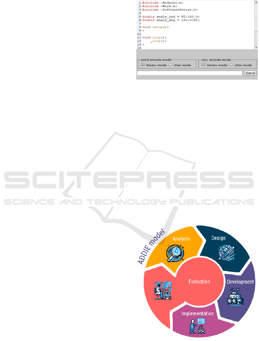
This was achieved by adding a code translator
module to the original Scratch code, that allows to
code in blocks and translate them to languages such
as C++ that the Arduino boards can be programmed
with (Figure 1). Also, the functionality to create and
add extensions to mBlock provides a higher degree of
integration with external hardware.
Figure 1: Arduino code generated by mBlock.
3 METHOD
Since the beginning, the development of the
prototype was done following an Instructional
System Design model (Clark, 2000), referred to as
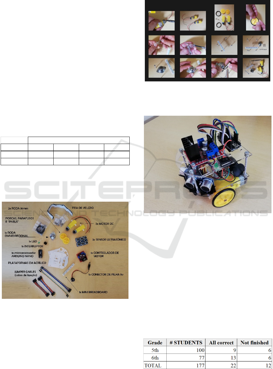
ADDIE, an acronym for Analysis, Design,
Development, Implementation and Evaluation
(Figure 2). In this article, we will describe another
cycle of development namely the phases of
Implementation, Evaluation, Analysis, and Design.
The Evaluation phase is fundamental and has been
a part of the process since the beginning. It supplies
information that feeds all the cyclic processes of
design and development. It’s very useful as a part of
the spiral of analysis, design, development, and
implementation as it contributes to the continuous
improvement of the prototype (Lencastre, 2012).
Figure 2: The ADDIE Model.
CSEDU 2024 - 16th International Conference on Computer Supported Education
160
3.1 Implementation
In the school year of 2018/2019, we implemented a
controlled test, in a real user scenario that involved
177 students, 100 from the 5
th
grade and 77 from the
6
th
grade of a Portuguese school. In that year, 6
lessons of the ICT and programming classes of those
students were dedicated to assembling Kid Grígora
and 6 more to use it, programming with mBlock.
The students in the study belonged to 8 different
classes, 4 from each of the 5
th
and 6
th
grades of
schooling. Classes had different durations for each
year of schooling, being 150 minutes for the 5th year
and 90 minutes for the 6th year. The distribution of
the students per class is seen in Table 1. Each class
had independent lessons and the students didn’t mix
while assembling the robot.
Table 1: Distribution of students per class.
At the beginning of the test, the students were
randomly distributed in the classroom and were given
a Kid Grígora kit with all the components they
needed to assemble the robot (Figure 3).
Figure 3: Parts on the Kid Grígora kit.
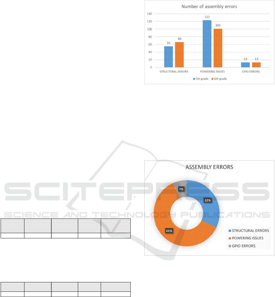
The assembly instructions consisted of a set of 194
detailed photographs and 5 videos, available online,
that allowed the students to build the robot step by
step (Figure 4).
Figure 4: Sample of the assembly instructions.
At the end of the test, all students were supposed to
have built a Kid Grígora robot (Figure 5).
Figure 5: Assembled Kid Grígora.
After the assembly test, all 177 robots were collected
by the responsible teacher and carefully reviewed,
with all assembly problems noted for later analysis.
3.2 Evaluation
From the 177 students, we registered 22
(approximately 12%) that finished the assembly
without any error. Also to take note is that 12 students
(approximately 7%) were not able to finish the robot
within the determined time (Table 2).
In total, we registered 330 errors distributed by 14
different types.
Table 2: Maximum and minimum results.
School year A B C D
5th26252425
6th17162321
Number of students per class
Designing Stemie, the Evolution of the Kid Grígora Educational Robot
161
To organize the collected data, we chose to
categorize it into meaningful categories, by assigning
a label to each one of the errors found.
Using categorization, allowed us to reduce our
results from 14 types of errors to 3 different
categories, more measurable and comparable:
• Structural Errors: issues related to the design
and physical structure of the robot. In this
category, we included all problems related to
mechanical aspects, such as the lack of
components in the final assembly, the fixing
points, missing wiring, or the assembly of the
robot;
• Powering Issues: related to the power supply to
all the components of the robot. In this category,
we included problems like missing power lines
for certain components and mixing GND and
Vcc or creating any sort of short-circuit;
• GPIO (General-Purpose Input/Output) errors:
errors that are related to the connections
between the Arduino microcontroller and the
rest of the components. We included all
incorrect wiring that may cause the input or the
control signals from working.
In both grades of schooling, as shown in Tables 3 and
4, most of the detected errors fell into the Powering
Issues category.
Table 3: Summary of detected errors for 5
th
-grade students.
As expected, the older students assembled the robots
with a lower average of errors per student, although
not much different.
Table 4: Summary of detected errors for 6
th
-grade students.
To better compare the results of both grades of
schooling, we normalized the data. The results of the
normalization can be analysed in Figure 6 and show
that older students ended up making more mistakes in
terms of structural errors than the younger ones.
However, in terms of wiring the components, the 6
th
graders had a better performance than the 5
th
graders,
with fewer errors in the Powering Issues category.
Figure 6: Normalized data comparison of assembly errors
between 5
th
and 6
th
graders.
In terms of percentage, the distribution of errors is
shown in Figure 7, with the category Powering Issues
being the one in which the most errors were detected
(61%). This very relevant information showed us that,
at least for this age range, the information present in
the assembly instructions needs to be more detailed in
terms of powering all the components of the robot.
Figure 7: Pie chart of assembly errors.
Overall the results were very good, especially
considering the age range of the students, with a
global average of errors per student of 1,86.
In the second part of the testing, during 6 lessons,
the same students used a simple framework,
developed in mBlock (Figure 8) to program their
robots in simple forward, backwards and turn
movements, while reasoning to make their robots
move and turn as straight as possible. In this part of
the test, only the students who completed the robot in
the previous task were involved.
# STUDENTS
STRUCTURAL
ERRORS
POWERING
ISSUES
GPIO
ERRORS
AVG/STUDENT
100 55 123 13 1,91
# STUDENTS
STRUCTURAL
ERRORS
POWERING
ISSUES
GPIO
ERRORS
AVG/STUDENT
77 51 78 10 1,81
CSEDU 2024 - 16th International Conference on Computer Supported Education
162
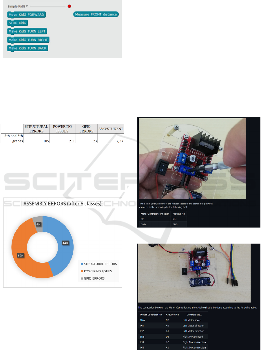
Figure 8: Extension developed for mBlock
After the 6 lessons, that functioned as a small stress
test for the hardware, all the robots were rechecked,
and the new problems were added to the initial results
table and shown in Table 5.
Table 5: Summary of detected errors after assembly and
stress test.
This new table shows that there was an increase in
both Powering and Structural issues. However, in
terms of Powering, the increase is around 5% while
in terms of Structural Errors, the increase was about
75% as seen in Figure 9. This fact also increased the
average of errors from 1,86 to 2,37 per student. In
terms of GPIO, there was no new record of errors.
Figure 9: Updated Pie chart of detected assembly errors,
after 6 classes stress test.
3.3 Analysis and Design Enhancements
The results after the 12 classes for assembly and stress
use showed that the platform, although usable, needed
some improvements in both Powering instructions
and in terms of Structure.
It is possible to perceive from Barradas et al.
(2019) that Kid Grígora’s simple structure was held
together by M3 screws and hex screw nut. Also, the 3
front sensors were held to the main platforms by
velcro tape. Although in the usability tests, there were
no problems reported related to those components,
what happens is that after some use, the hex screw
nuts tend to get loose if not tightened well, and the
structure was shaken. This fact caused almost every
occurrence of errors in the structure, post-assembly.
In terms of Powering issues, they were related to
faulty batteries and bad soldering, not detected on the
first inspection.
As we previously mentioned, to try to solve the
Powering issues, we decided to create more detailed
assembly instructions, using the same type of pictures
but adding detailed text and tables with information
on where to connect each of the jumper cables in the
robot. (Figure 10).
Figure 10: Updated assembly instructions.
Figure 11: L298N connection to Arduino Nano.
Designing Stemie, the Evolution of the Kid Grígora Educational Robot
163
Although there were not many errors in terms of
GPIO, we decided that the new instructions should
also have a table with every IO pin used in Arduino
(Figure 11).
To cope with structural problems, we decided to
change the structure holding points and don’t use the
M3 screws anymore, as we concluded that, for
children of this age, that wasn’t the best solution.
After browsing the market for solutions, we chose to
use M3 brass female spacers instead.
3.3.1 Upgraded Hardware Components
Remembering that we were creating an educational
tool, the decision to upgrade the hardware came from
the idea of enhancing the educational impact of our
robot. As we were making changes, we decided to
create a more versatile platform with other types of
sensors and actuators. This should allow both
students and teachers to use it, integrated with more
scientific and technological subjects. Increasing
problem-solving scenarios enables students to engage
in more challenges across multiple STEM subjects
and not only Robotics.
After meeting with teachers from STEM subjects
such as Sciences, Physical Chemistry and Maths, the
changes in Table 6 were made:
Table 6: Comparison of changed components.
Old version Upgraded version
3 Ultrasonic sensors 1 Ultrasonic Sensor
1 Green LED 1 RGB LED
- 3 Infrared line sensor
M3 screws M3 brass female spacers
Velcro Tape Nano PU Gel Tape
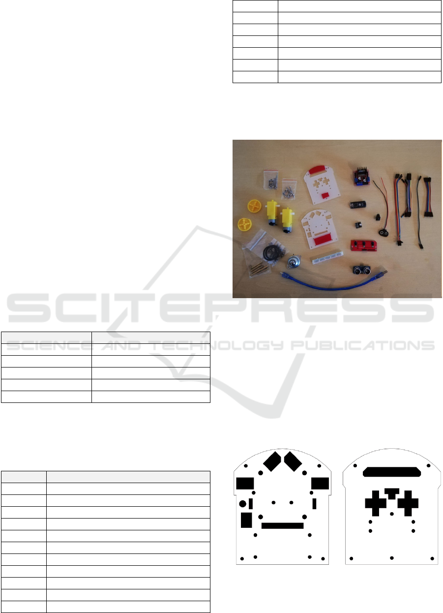
Due to these changes, the list of components of the
upgraded version of our robot is the one in Table 7
and Figure 12.
Table 7: List of components of Upgraded Version.
Quantity Component
1 Arduino Nano
2 Geared DC Motor
1 3-channel infrared tracking module
1 HC-SR04 Ultrasonic Sensor
1 L298N DC Motor Driver
1 RGB LED module
1 9v Battery Holder Clip
1 Mini ON-OFF Switch
1 Mini Breadboard
1 USB cable
35 Jumper cables (10/20 cm, M-F & F-F)
1 Caster Ball
2 Plastic Wheels
4 Spacer M3 10mm
4 Spacer M3 30mm
2 Motor Bracket Holder (with screws)
2 Acrylic Platform 3mm
2 O-Ring
The upgraded version would still be controlled by an
Arduino Nano, as this small microcontroller proved
to be very reliable and its small form factor is very
important for this project.
Figure 12: Components of the upgraded version.
Due to these small, but important, changes, the main
platforms had to be slightly modified to accommodate
the new components. The initial idea from Barradas
et al. (2019), was to use 3D printed platforms for the
robot. The robots used in the test we described
already used acrylic laser cut platforms, much more
inexpensive than the 3D printed version. For this
upgraded version we opted to maintain the acrylic
version but also have the option to use laser-cut MDF
(Figure 13).
Figure 13: New design of the platforms.
CSEDU 2024 - 16th International Conference on Computer Supported Education
164
These new platforms were made specifically for the
two planned versions of our robot. The top platform,
with specific holes for signal and power wires that
connect to Arduino, holes for motor current wires, a
specific one to place a power switch, and another one
for the LED. As for the lower platform, there are
specific rounded holes to attach the motor bracket
holders and the Caster ball, as well as wholes for the
jumper cables to go through to the breadboard and
components like the 3-channel infrared tracking
module and the HC-SR04 Ultrasonic Sensor. Both
platforms also have round 3mm holes to attach the
brass spacers that will join the two platforms and give
the robot stability. The design of these platforms also
reflects the changes needed for the future upgraded
version of Kid Grígora Semi-Pro, not the object of
this article.
3.3.2 Programming Interfaces
The main idea about the programming interfaces used
in Kid Grígora remains in this upgraded version: to
build a programming framework, simple enough to be
used by small children, allowing them to explore the
full potential of the robot.
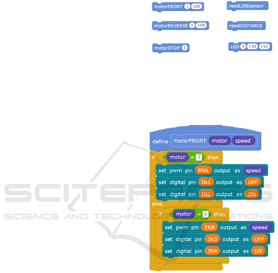
However, due to the new features added, as the
new components demand new programming
functions, we had to develop a different set of
commands. Looking at Figure 14, it is possible to
perceive some differences in the developed
framework for this version. We decided to use a
terminology where the two engines can be controlled
separately and with different speeds. To do so, we
created a motorFRONT procedure that moves the
motors forward and allows us to change the speed of
each of them, by using it with its number (motor 1,
Right side, or 2, Left side). Following the same idea,
we created a motorREVERSE procedure that moves
the motors backwards, and a motorSTOP that stops
each motor. Combining these blocks you can control
both motors, each one of them independently,
allowing the students to create their own set of
movements. In terms of using the sensors, we created
a readDISTANCE procedure that allows easy use of
the ultrasonic sensor and a readLINEsensor
procedure that reads the floor under the sensor to try
to find out whether there is a white or black line to
follow. To allow an easy way to use the RGB LED,
we created a LED procedure, fed with the RGB values
of the colour you want to display on the LED.
Figure 14: Programming framework.
The framework was built in a way that the teachers
and more advanced students could analyse all the
details of the programming. Instead of creating a
black box with impossible-to-analyse functions, we
created simple procedures in mBlock, leaving all the
code visible for them to study and change if needed
(Figure 15).
Figure 15: Procedure motorFRONT.
3.3.3 Add-on Features
More than to develop a robot, we wanted to create
something that children could relate to and would like
to use and learn about.
To make the robot more attractive to children, we
decided to create some add-ons to allow
personalization. Using personalization, we expect to
create a sense of ownership and identity so that
children should become more attached to the robot.
Personalization also allows them to express their
creativity in aspects such as choosing colours,
accessories, or even other design features.
Designing Stemie, the Evolution of the Kid Grígora Educational Robot
165
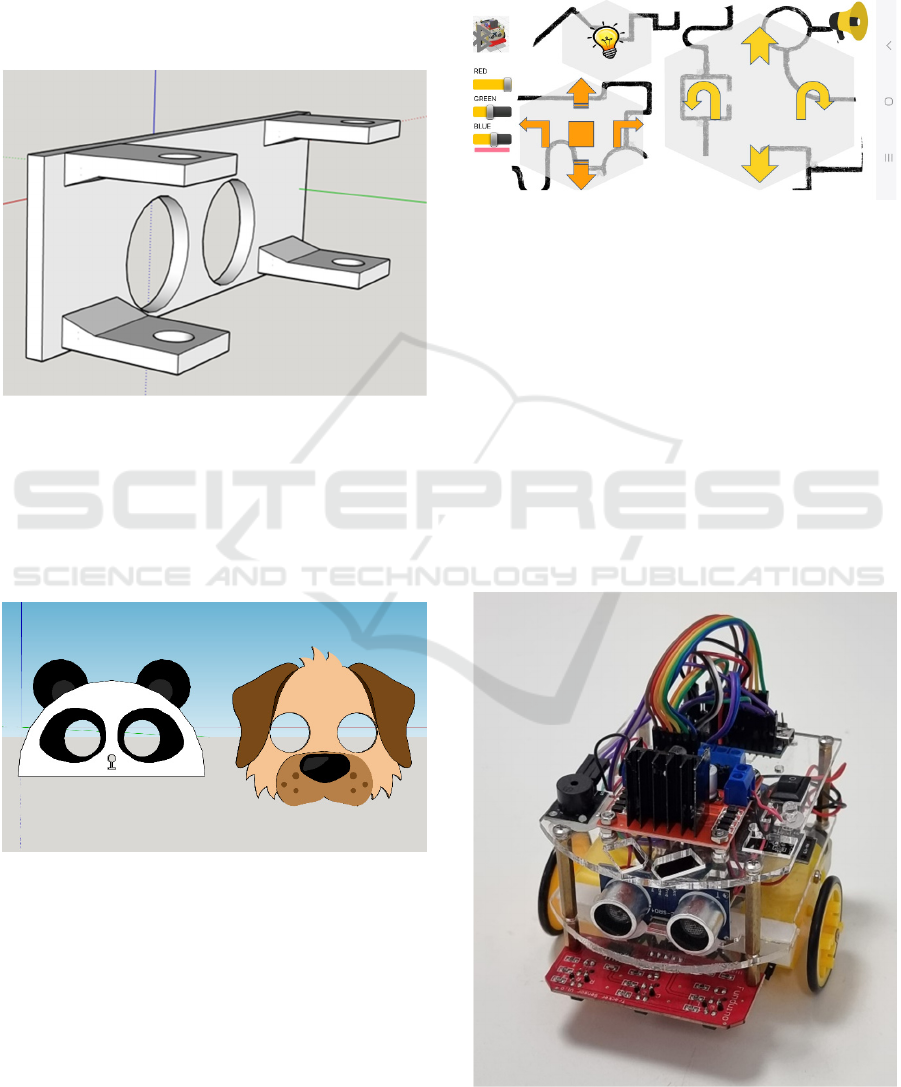
To easily allow personalization, we developed a set
of 3d printed parts, that can also be replicated in
cardboard, in case there is no 3d printer available.
One of the 3d printed parts is a mask adapter (Figure
16). It’s a part that can be attached to the front of the
robot, holding onto the brass spacers. With holes for
the Ultrasonic sensor, this 3d printable part allows
children to build a mask and attach it to the robot.
Figure 16: 3D printable mask adapter.
In the case of younger children who could find it hard
to build their masks, we also created some 3D
printable add-on masks just for the children to paint.
These masks attach to the mask adapter and children
could choose from a set of different characters
(Figure 17).
Figure 17: 3D printable masks.
Also in the add-on category, and with the idea of
adding some extra features to our robot, we developed
an App for Android, with which children can control
their robots by phone.
After uploading a specially designed firmware to
the Arduino and connecting an HC-05 Bluetooth
module, it is possible to use the app to control the
movements and some other features of the robot. The
development of firmware was done in mBlock, to
maintain the coherence with the rest of the code and the
Stemie ControlApp (Figure 18) was developed in MIT
(Massachusetts Institute of Technology) AppInventor
a visual programming environment, Blocks-based, to
create Android Apps, developed by the MIT.
Figure 18: Screenshot of the Stemie ControlApp.
3.4 Development
Building upon the concepts and the prototype by
Barradas et al. (2019), the original idea of Kid
Grígora was to have an educational robot that could
be used as a teaching tool to be integrated into the
curriculum. Also, a secondary objective was that it
had to be designed small enough to allow children to
use it in the Micromouse Portuguese Contest.
All the changes we made in this upgraded version led
to a robot that, in its base version, is not capable of
participating in that competition, but that’s more
usable in general, in STEM areas. Because of that,
from now on, it will be known as Stemie (Figure 19).
Figure 19: Stemie the robot.
CSEDU 2024 - 16th International Conference on Computer Supported Education
166
3.4.1 Building the Second Beta Version
Stemie was built upon Kid Grígora’s foundations,
with a different design but simpler and faster to build.
After its construction, it was then, subjected to a
test in a heuristic evaluation by experts. This
evaluation had the objective of appraising both
usability and potential design problems and gathering
suggestions from the experts on how to solve the
problems they found and, possibly, add new features.
To test the prototype, we chose double experts
(Nielsen, 1993) experienced not only in usability but
also with specific expertise in robotics as they
potentially find 1.5 times more problems than simple
usability specialists (Nielsen, 1993). We used three
ICT and Robotics teachers from 3 different countries
(Italy, Lithuania and Croatia).
The evaluations were carried out according to
each expert’s agenda and started with an explanation
of the expected use of Stemie by end-users, as a
STEM tool. The evaluators had knowledge of the
previous version and had previously been given the
new robot’s parts and the updated assembly
instructions, and were asked to assemble it.
After the tests, each expert was asked to fill out a
heuristic evaluation questionnaire to report possible
problems, by using Nielsen’s severity rating scale
(Nielsen, 1993). In this scale, they used numbers from
0 to 4 in which 0 means "I don’t agree that this is a
usability problem at all" and 4 means a "Usability
catastrophe: imperative to fix this before the product
can be released".
About the strong points of the heuristic
evaluation, all the experts mentioned the evolution in
structure stability, using brass spacers instead of
screws and hex nuts and that the robot should be even
easier to build now. Although like in Kid Grígora’s
evaluation, all the experts said that it was a good idea
to use standard electronic components, easy to find
and replace, in case of malfunction. Also mentioned
was the large number of problem-solving tasks that it
is possible to solve using Stemie. Two of the experts
mentioned the fact that the instructions were very
detailed on both the electrical connections and the
GPIO pins, which would make it easier for children
to assemble the robot.
The weakest points in the heuristic evaluation
(ratings 3 and 4) are summarized in Table 8.
Table 8: Severe and catastrophic errors found, according to
Nielsen’s heuristics.
Nielsen’s heuristics
Interface (IN) Degree
IN1 Visibility of system status 3
IN5 Error prevention 4
Regarding IN1, one of the experts mentioned, that
although Stemie had an LED to visibly show the
system status, it would be more useful if it also had
audible status. Related to IN5, all of the experts stated
that there was an error in the connection of pin A6 to
the 3-channel infrared tracking module, as A6 and A7
on an Arduino Nano are pure analogue pins and
cannot be used as digital pins. Only A0-A5 can be
used as digital pins in that build of Arduino.
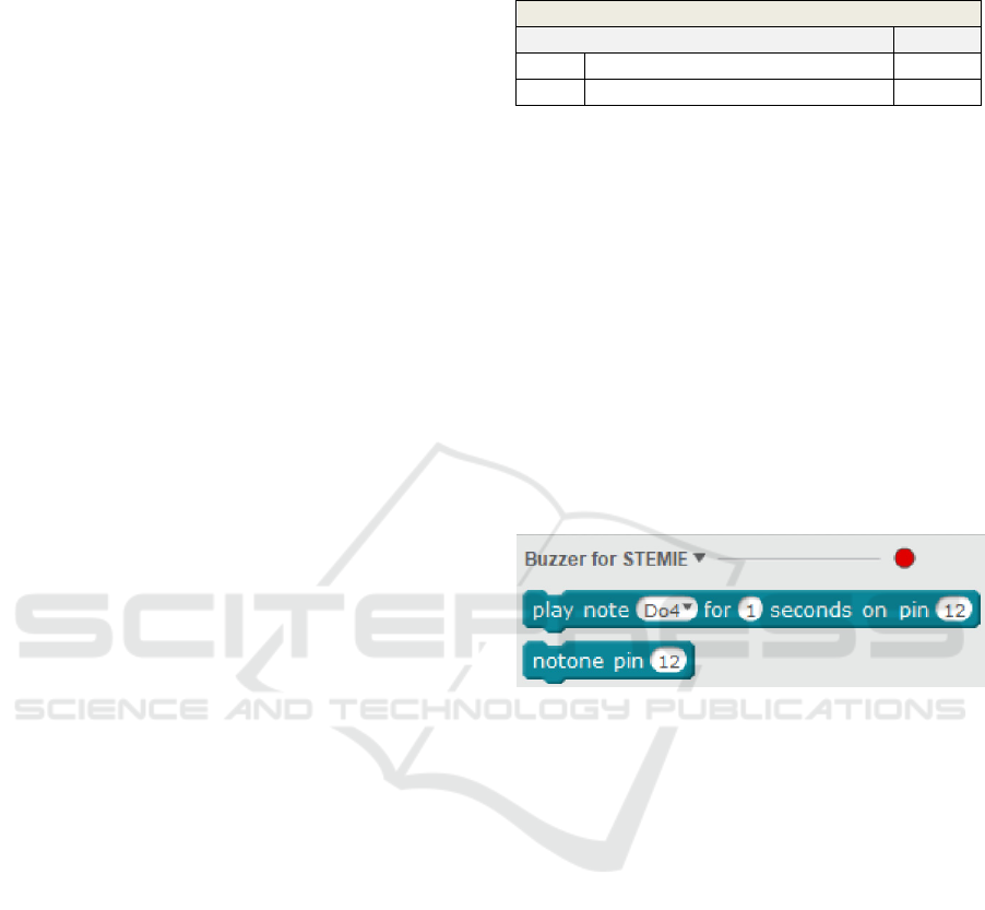
The results of the heuristics analysis led to some
changes in the final product. Regarding IN1, we
decided to add a Buzzer module to the parts list, add
a new chapter to the Assembly instructions and create
a mBlock extension (Figure 20) to allow the Buzzer
to be used as a musical instrument, allowing even
more activities to be done with Stemie.
Figure 20: Buzzer for Stemie extension.
Using the mBlock platform that allows users to write
custom extensions programmed in JavaScript, in a
way to add new functionalities to the programming
environment, we created two new blocks to be used
by students. The extension is made by two essential
parts: the definition of the block that shows in the
mBlock application and the translation to C++ code
which can be uploaded to the Arduino Nano for
execution. The following is an example of the code:
"extensionName": "Buzzer for
STEMIE",
"description": "An extension for
using a Buzzer with STEMIE",
"version": "1.5",
"author": "",
"homepage": "",
"sort":0,
"javascriptURL":"js/buzzer.js",
"firmware":"1.0",
"extensionPort":0,
"blockSpecs": [
[
"w",
Designing Stemie, the Evolution of the Kid Grígora Educational Robot
167
"play note %d.notes for %n seconds
on pin %n",
"tone",
"Do4", "1", "12",
{
"setup":"pinMode({2},OUTPUT);\n",
"inc":"",
"def":"",
"work":"tone({2},{0}, {1}*1000); //
write to buzzer\ndelay({1}*1000);",
"loop":""
}
],
[
"w",
"notone pin %n",
"notone",
"12",
{
"setup":"pinMode({0},OUTPUT);\n",
"inc":"",
"def":"",
"work":"noTone({0});\n",
"loop":""
}
]
]
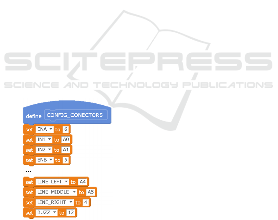
To solve IN5, we changed the assembly instructions,
moved the connection from pin A6 to pin D4, and
made some changes in the programming framework
to reflect those changes. To make it even easier to
perform such changes in the future, we added to the
Framework a procedure where all the GPIO pins can
be configured by the final user (Figure 21).
Figure 21: Excerpt from the config_connectors procedure.
7 CONCLUSIONS
Built upon Kid Grígora, Stemie marks a significant
evolution on our educational robotics platform,
aligning it with the requirements of STEM education.
The comprehensive testing we’ve done with 177
students from a Portuguese School led to some
valuable insights on assembly errors and showed us
how important it was to have even more detailed
instructions, especially due to the age range of our
end-users. Following the ADDIE model, we
analysed, implemented and evaluated, and from the
collected information we addressed both structural
and powering errors found by the end users.
After the test and further analysis, we upgraded some
of the hardware in the robot which allows students to
explore even more scientific experiments, promoting
computational thinking and problem-solving skills in
even more STEM subjects. The heuristic evaluation
by STEM experts provided even more feedback on
the design and allowed the correction of some errors.
As STEM education evolves, it’s up to us to create
tools that allow children to learn while playing.
8 FUTURE WORK
Future work includes usability tests with
representative end-users and a real stress test. It also
includes the full development of Stemie,
complemented with STEM exercises to use in
educational environments. Stemie’s Extended
edition, for older students, equipped with different
sensors and actuators, will also be a focus, aligning
our work with the original idea of participation in the
Micromouse Contest.
ACKNOWLEDGEMENTS
This work was partially funded by FCT-Fundação
para a Ciência e a Tecnologia (FCT) I.P., through
national funds, within the scope of the
UIDB/00127/2020 project (IEETA/UA,
http://www.ieeta.pt/ (accessed on March 2nd 2024)),
https://doi.org/10.54499/UIDB/00127/2020,
https://doi.org/10.54499/UIDP/00127/2020
This work is partially funded by CIEd – Research
Centre on Education, Institute of Education,
University of Minho, projects UIDB/01661/2020 and
UIDP/01661/2020, through national funds of
FCT/MCTES-PT.
CSEDU 2024 - 16th International Conference on Computer Supported Education
168

We want to thank Colégio Paulo VI (Gondomar,
Portugal), and the students of the 5th and 6
th
school
years, for their collaboration and the authorisation to
perform this research on their premises.
REFERENCES
Barradas, R., Lencastre, J. A., Soares, S., & Valente, A.
(2019). Usability evaluation of an educational robot for
STEM areas. In H. Lane et al. (ed) Proceedings of the
11th International Conference on Computer Supported
Education (CSEDU2019), Volume 2 (pp. 218-225).
Heraklion, Crete, GR: SCITEPRESS – Science and
Technology Publications.
Barradas, R., Lencastre, J. A., Soares, S., Valente, A., 2021.
The code.org Platform in the developing of
Computational Thinking with elementary school
students. In: H. Lane et al. (Eds) Computer Supported
Education. Csedu 2020. Communications In Computer
And Information Science, Vol 1473. Springer, Cham.
https://Doi.Org/10.1007/978-3-030-86439-2_7
Jonassen, D., 2011. Learning to solve problems. A
Handbook for Designing Problem-Solving Learning
Environments. Routledge.
Lencastre, J. A., 2012. Educação on-line: análise e
estratégia para criação de um protótipo. In J. B.
Bottentuit Junior et al. (org.), Educação on-line:
Conceitos, metodologias, ferramentas e aplicações (pp.
127-136). Editora CRV.
Mblock.cc. (2023). [online] Available at:
http://www.mblock.cc [Accessed 16 Jan. 2024].
Nielsen, J., 1993. Usability Engineering. Morgan
Kaufmann.
Resnick, M., Maloney, J., Monroy-Hernandez, A., Rusk,
N., Eastmond, E., Brennan, K., Kafai, Y., 2009.
Scratch: Programming for All. Communications of the
ACM, 52, 60-67.
Resnick, M., 2012. Reviving Papert's Dream. Educational
Technology, vol. 52, no. 4, pp. 42-46.
Scratch Foundation. (n.d.a). [online] Scratch - About.
Available at: https://scratch.mit.edu/about [Accessed
16 Jan. 2024].
Scratch Foundation. (n.d.b). [online] Scratch for Educators.
Available at: https://scratch.mit.edu/educators
[Accessed 16 Jan. 2024].
Silva, S., Soares, S., Valente, A., Barradas, R. Bartolomeu,
P., 2015. Enhancing STEM courses through a robotic
innovative project. Proceedings of the 3rd International
Conference on Technological Ecosystems for
Enhancing Multiculturality - TEEM ’15, Porto,
Portugal. doi: 10.1145/2808580.2808668
Wing, J. M., 2007: Computational Thinking. Retrieved on
2019/05/01, from https://www.cs.cmu.edu/afs/cs/usr/
wing/www/Computational_Thinking.pdf.
Wing, J. M., 2017. Computational thinking’s influence on
research and education for all. Italian Journal of
Educational Technology, 25(2), 7-14. doi: 10.17471/24
99-4324/922
Designing Stemie, the Evolution of the Kid Grígora Educational Robot
169
