
On Some Artificial Intelligence Methods in the V-Model
of Model-Based Systems Engineering
Stephan Rudolph
Institute for Aircraft Design, University of Stuttgart, Pfaffenwaldring 31, 70569 Stuttgart, Germany
Keywords:
Artificial Intelligence, V-Model, Model-Based Systems Engineering.
Abstract:
The enhancement of the standard V-Model of Model-Based Systems Engineering (MBSE) with methods from
Artificial Intelligence (AI) is currently in the research focus of many universities and engineering companies.
In the need to find new means to deal with the steadily increasing complexity in modern systems engineering
and design of complex systems, traditional MBSE methods, most notably the standard V-Model of MBSE, is a
candidate to be enriched with several AI methods. The work presented summarizes the experience gained with
several AI methods in a machine-executable version of the V-Model of MBSE based on an graph-based design
language approach to design automation and tries to summarize the resulting shift in the engineering burden
and effort as well as the observed gains in design time and quality. Based on the results from engineering
practice and some theoretical foundations underlying engineering as a branch of the natural sciences per se,
an outlook is attempted on some necessary aspects in future developments of AI for engineering applications.
1 ENGINEERING BACKGROUND
As necessary background knowledge and engineering
context for the work presented hereafter, the standard
V-Model of MBSE is shown in figure 1.
Figure 1: The standard-V-Model of MBSE.
The standard V-Model of MBSE starts on its left
side with a three-fold mapping sequence of the de-
sign requirements onto the three intermediate design
representations via a subsequent mapping of the re-
quirements onto the functional system architecture
model onto the logical system architecture model onto
the physical system architecture model. At the end
of this decomposition procedure, components design
and build occurs and in the subsequent integration
phase the components are integrated to system mod-
ules. Finally, the system modules are integrated to the
system on the right side of the V-Model, according to
the devised system architecture.
Dedicated procedures for verification and valida-
tion (V&V) intend hereby to guarantee in the V-model
in figure 1 that the original system design intent is
maintained (by selected verification methods, often
by formalisms) and that the design requirements are
met at the devised (sub-)system levels (by selected
validation methods, often by simulation or experi-
ment). Human systems engineering experts usually
“know”
1
how to decompose, structure, manage and
steer the flow of information of the dedicated design
teams for subsystems, components, simulations and
the like, as shown in figure 1. The underlying patterns
of decomposition and verification and decomposition,
integration and validation can hereby occur at various
levels of detail, showing that the design process may
be of fractal nature with repeating patterns at all rele-
vant scales of detail.
Humans seem to have no general problem with the
aforementioned, apparently weak scientific nature of
knowing, since humans switch easily back and forth
between textual, graphical and symbolical representa-
tions and their appropriate reasoning mechanisms. If
1
The scientific nature of this “know(ing)” is key to the
application of AI methods to engineering, since this is not
a pure, deductive process but resembles more an individual,
intuitive search process. Mimicking this process later by AI
methods seems thus straightforward and has led in the past
to the famous paradigm “design is search” (Simon, 1969).
386
Rudolph, S.
On Some Artificial Intelligence Methods in the V-Model of Model-Based Systems Engineering.
DOI: 10.5220/0012639700003645
Paper published under CC license (CC BY-NC-ND 4.0)
In Proceedings of the 12th International Conference on Model-Based Software and Systems Engineering (MODELSWARD 2024), pages 386-393
ISBN: 978-989-758-682-8; ISSN: 2184-4348
Proceedings Copyright © 2024 by SCITEPRESS – Science and Technology Publications, Lda.

however a machine or an algorithm needs to mimic or
replace these human capabilities, first an appropriate
formalization step is mandatory. In this required for-
malization, an appropriate mathematical model which
provides an adequate mapping of the real-world prob-
lem into a machine-readable form of representation
2
has to be provided.
1.1 Formalization of Data and Processes
To formalize an engineering problem mathematically,
the concept of models and transformations between
the models
3
needs to be introduced. The models M
0
and M
N
represent a hereby a formal and machine-
readable representation of an object or space. The
transformation T
(0,N)
describes how the model M
0
is transformed into the model M
N
, as shown in fig-
ure 2 (Hahn and Rudolph, 2023).
Figure 2: Definition of the model transformation T
(0,N)
.
The transformation T
(0,N)
can be further splitted
and decomposed into a sequence of smaller transfor-
mations T
(0,I)
and T
(I,N)
with 0 < I < N. However, the
smallest possible transformation is the transformation
T
(I,I+1)
which transforms (i.e. modifies) at least one
atomic element of the model representation M
I
into
M
I+1
. An atomic element of a model is hereby a rep-
resentational element which is not further decompos-
able in the chosen representation. The shown trans-
formation T
(I,I+1)
corresponds to such a smallest pos-
sible level of detail of modification in the engineer-
ing model concept, as shown in figure 3 (Hahn and
Rudolph, 2023).
Figure 3: Decomposition of T
(0,N)
down into T
(I,I+1)
.
The digital modeling of engineering data and pro-
cesses is therefore straightforward possible using the
above introduced concept of models and transforma-
tions. As a first flavor how this is used in the following
section to formalize the V-Model serves the following
statement: Supposed M
0
in figure 2 represents the re-
2
This formal representation needs to fulfill furthermore
the “closed-world assumption”, in order to guarantee that
the still unknown solution can be in fact found by a search
procedure, leading otherwise the concept of the paradigm
“design is search” ad absurdum (Simon, 1969).
3
The terms model, transformation and later even model
transformation are used in mathematics, engineering and
computer science in slightly different settings. In this work
it is taken special care to make clear in the context which of
the multiple meanings is intended.
quirements model, and M
N
represents the final prod-
uct or system model, then the transformation T
(0,N)
represents the philosophy of requirements-driven en-
gineering, stating that the final product M
N
should be
designed with the intention in mind to exactly fulfill
the requirements M
0
.
In the sense of the research question of finding an
adequate decomposition of meaningful transforma-
tions according to figure 3, a requirements-driven en-
gineering means to find an explicit solution sequence
of transformations which models the design process
as a sequence of intermediate steps. In consequence,
model transformations may therefore be few in num-
bers during the early concept design phase, during
the later detailed design phase hundreds, thousands
or even more model transformations maybe used to
digitally encode the design process knowledge.
1.2 Digital Machine-Executable
V-Model
All the engineering models and engineering tasks in
the standard V-Model of MBSE shown in figure 1 can
now be formalized as (sequences of) transformations
which transform one state of a model into another.
These transformations are ideally suited for such a
formalisation, digital programming and, as a direct
consequence, to obtain in consequence a machine-
executable V-Model (Walter et al., 2019; Walter et al.,
2018), of which the intermediate model states are
shown in figure 4 (Hahn and Rudolph, 2023).
Figure 4: Digital machine-executable V-Model.
The legend for figure 4 is as follows: requirements
model (M
R
), functional architecture model (M
FA
),
logical architecture model (M
LA
), physical architec-
ture model (M
PA
), component models (M
C
), subsys-
tem module models (M
SM
) and system model (M
S
),
transformations shown as directed arrows.
On Some Artificial Intelligence Methods in the V-Model of Model-Based Systems Engineering
387

1.3 Properties of Model Spaces
Two different digital and mathematical properties are
most interestingly to note in the digital machine-
executable V-Model shown in figure 4.
Firstly, the emphasis in the visual representation
lies on the models, which are usually implemented as
digital data structures in the form of linked data ob-
jects, lists, trees or graphs thereof. Figure 4 resembles
therefore much of a static data flow graph visualiza-
tion, which may be dynamically updated incremen-
tally by the tranformation T
I,J
with (0 < I < J < N)
from model M
I
into the new model M
J
.
Secondly, the different models M
I
, M
J
do not nec-
essarily exist in the same model spaces. As mentioned
in the introduction, humans are very good to mix or
switch easily back and forth between textual, graphi-
cal and symbolical representations and their appropri-
ate reasoning mechanisms. Usually algorithms don’t
possess this easiness of representation changes and
must therefore specifically adapted to such different
spaces. It is therefore important to check and know
the different nature of model spaces involved when
digitizing the V-Model.
From common general engineering experience,
the following different spaces can be identified:
• Verbal Spaces.
Design requirements are either expressed in hu-
man languages textually or already expressed for-
mally. In languages such as English and German,
each noun (i.e. vocabulary defined in a dictionary)
is the name of a concept. A mathematical for-
malization by means of formal concept analysis
allows the formal definition of super- and sub-
concepts as well as the formal definition of char-
acteristic dependencies between the concepts ex-
pressed in the form of links.
The digital encoding of the concept properties in
an object-oriented programming language (such
as JAVA) or a modern visual modeling language
(such as UML) yields an object-oriented model of
that domain, i.e. an ontology. Using the afore-
mentioned graph-based representation allows to
model such domain ontologies by means of ab-
stract nodes and specialized links.
• Logical Spaces.
Customers can typically choose from a huge vari-
ety of product options in order to configure their
future product. These are often expressed as
Boolean constraints and can be handled and pro-
cessed efficiently by dedicated algorithms for spe-
cialized types of binary trees.
Again, the processed results can be represented in
the form of abstract nodes with specialized links.
• Real-valued Spaces.
Mathematics, physics and most other natural sci-
ences make heavy use of this space in which
a large variety of functional relationships in the
form of linear, nonlinear, integral, and differen-
tial equations etc. as well as even systems of such
equations and many more other useful mathemat-
ical operands and operations exist. Fortunately,
in this case the formalization in form of a formal
language (i.e. mathematics itself) already exists
and has led to the availability of many algorithms,
toolboxes and solvers for processing typical (dif-
ferential) equations and equation systems occur-
ring in engineering (e.g., solvers for FEM, MBS,
CFD, etc.).
Once again, the results can be represented in the
form of abstract nodes with specialized links.
• Functional, Logical, and Physical System
Architecture Spaces.
Many widely used engineering design methods,
ranging from the more traditional systematic Ger-
man design methodology (Pahl and Beitz, 1996)
up to the more modern machine-executable V-
Model of MBSE in figure 4, advice to map the
design requirements subsequently via the inter-
mediate design representations of the functional
system architecture model to the logical system
architecture design model to the physical system
architecture design model.
Functional architecture representations are often
represented as graphs and so are logical architec-
tures in the form of block diagrams also repre-
sentable as graphs. Physical architectures are typ-
ically represented in 3D metric spaces, often in the
form of parametric CAD models, internally repre-
sented as graph-based data structures as well.
From the above analysis of the properties of the differ-
ent spaces, it can be stated that a graph-based design
representation is the common denominator to repre-
sent design information. Such graph-based represen-
tations are capable to model parametrical as well as
topological design information in a unified represen-
tation and graph transformation processing mecha-
nisms. The design information can come from var-
ious and heterogeneous spaces, with different levels
of abstraction and detail. If such a generic graph-
based data representation is freely accessible inside
a performant digital modeling and processing frame-
work and can be mapped to open standards (such as
UML or SysML) in order to exchange information
with other engineering modeling and analysis tools,
this can be summarized as the key concept of graph-
based design languages (Riestenpatt gen. Richter and
Rudolph, 2019).
MBSE-AI Integration 2024 - Workshop on Model-based System Engineering and Artificial Intelligence
388

1.4 Graph-Based Design Languages
The core mechanism of graph-based design languages
consists of the encoding of any engineering concept
of interest as an abstract graph node and to express
any existing dependencies or couplings, either disci-
plinary or multi-disciplinary, by dedicated links be-
tween the graph nodes. The traditional terminology
in design languages is the vocabulary (for the build-
ing blocks of the models), the rules (for the transfor-
mations) and the production system for the rule se-
quence embedded in the control structures to define
a program for compilation (Riestenpatt gen. Richter
and Rudolph, 2019).
The effort of programming in graph-based design
languages consists thus of writing down a sequence
of graph transformations (Voss et al., 2023) which
may be intermixed with conventional control struc-
tures known from other programming languages to
guarantee that in a certain moment at the end of a
design computation a certain result is obtained or
another computational iteration loop is triggered to
achieve the desired result, see figure 5.
Figure 5: Model generation, simulation and evaluation loop
by compilation of design languages (Rudolph, 2011).
Like any other formal programming language in
computer science, graph-based design languages need
a language compiler to translate the design language
(i.e. the source-code) into an executable engineering
model (i.e. a CAD-model). In the work here, the com-
mercial software product Design Cockpit 43
®
(IILS
mbH, 2023) is used as a compiler to translate graph-
based design languages into executable models for
the purpose of design automation (Rudolph, 2011;
Schmidt and Rudolph, 2016).
The automation of a design loop of a complex
system in modules of graph-based design languages
opens the horizon to substitute selected design lan-
guage modules by modules with artificial intelligence
exhibiting the same input-output relation.
2 ARTIFICIAL INTELLIGENCE
IN ENGINEERING DESIGN
In the following three paragraphs, several artificial in-
telligence search strategies are used to create a phys-
ical architecture from a given logical architecture.
Since all three problems of packing, piping and rout-
ing are known to be NP-complete (Sahni and Bhatt,
1980; Leung et al., 1990; Cagan et al., 2002), no
global optimum solution can be expected in reason-
able run-time for industry-size problems.
This bottleneck opens the window for all kinds
of search heuristics to reduce the run-time at the ex-
pense of optimality. In most real-world industrial ap-
plications, the notion of optimality seems mostly to
be an illusion anyway, since the often mandatory de-
sign constraints (i.e. internal design codes and exter-
nal standards and norms) are observed to dominate
the solutions found. In AI exists a wide range of al-
gorithms with divers setups and with different mathe-
matical properties and search characteristics, ranging
from stochastic to deterministic behaviors.
In a particle multiple swarm optimization (PMSO)
algorithm exist several sets of design solution candi-
dates in parallel, while in an a simulated annealing
(SA) algorithm (Kirkpatrick et al., 1983) only a single
set of design solutions exists. Such algorithms also
possess a set of parameters to modify the algorithmic
behavior and need therefore some experience in cus-
tomizing the algorithm to a specific search problem.
If one or several parameters in these algorithms are
randomized, the behavior of the algorithm becomes
stochastic. In other cases when the design problem
can be mapped to a graph representation, in which a
shortest path connection problem needs to be solved,
several graph search algorithms are available as so-
lutions, and the A
∗
-algorithm (Eheim et al., 2021) is
known to be optimal, complete and deterministic.
In the following sections three applications of AI
search algorithms (PMSO, SA and A
∗
) are used for
the automated packing, piping and routing in arbitrary
complex 3D CAD-geometries.
2.1 AI in Packing Automation
In the V-Model in figure 4 the logical architecture de-
fines the list of system components and their intercon-
nections. This serves as input for a packing algorithm
which defines the boundary conditions for the subse-
quent piping and routing algorithms inside a certain
design space. The AI algorithm used is a particle mul-
tiple swarm optimization (PMSO) algorithm (Schop-
per, 2023), which allows to consider constraints of all
kinds to be included in the optimization.
On Some Artificial Intelligence Methods in the V-Model of Model-Based Systems Engineering
389
The optimization goal is the overall minimization
of the layout area, and as additional constraint, only
straight connections between the components are al-
lowed, see figure 6. While in figure 6 the optimization
Figure 6: Automated PMSO packing (Schopper, 2023).
goal was the layout minimization under the constraint
of only straight connections between the components,
the layout can be further compacted if bends of 90
◦
between the components are allowed, see figure 7.
Figure 7: Automated PMSO packing (Schopper, 2023).
The difference of the two bending conditions in
figures 6 and 7 results in a 21 % area saving from
457cm
2
to 361cm
2
for the generated packages.
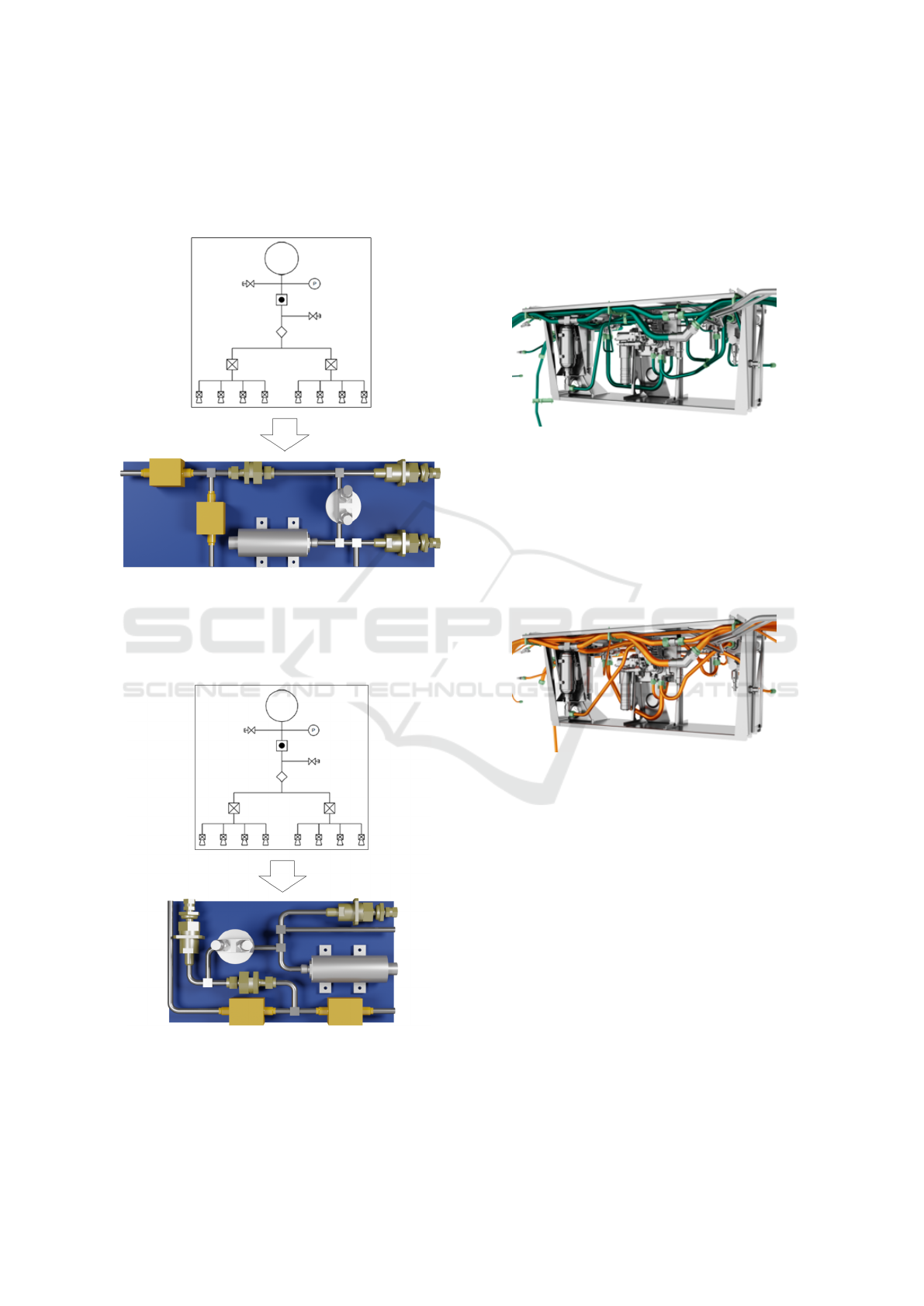
2.2 AI in Piping Automation
The following pipings stem from a comparison of an
Airbus A320 landing gear bay, which was manually
designed, and was now compared in an industrial case
study with pipings obtained by a simulated annealing
(SA) algorithm (Neumaier et al., 2022).
Figure 8: Manual Airbus A320 series piping with total pipe
length 22.6m and 107 bends) (Neumaier et al., 2022).
The comparison of the manually designed A320
series solution in figure 8 and the generated piping in
figure 9 yields a 8, 4 % length and weight saving at the
expense of a surplus of 43 bends.
Since the number of bends drives the cost for man-
ufacturing, a second industrial case study showed that
the algorithm could be further improved to yield an
Figure 9: Automated Design Cockpit 43
®
piping with total
pipe length 20.7m and 150 bends) (Neumaier et al., 2022).
even more reduced total pipe length of 20.4 m and re-
duced number of only 95 bends, resulting in a com-
bined saving of 9, 7 % in total length and weight and
a 11, 2% saving in bends (Rudolph, 2023).
2.3 AI in Routing Automation
While the previous showcases of packing and piping
were from aerospace, the following routing automa-
tion application is taken from the automotive industry.
Routing comes in industry usually after the piping,
since wires are more flexible than pipes and previ-
ously no software system could handle both problems
in a common framework simultaneously. Figure 10
shows a routing generated with a modified version of
an A
∗
-algorithm (Eheim et al., 2021).
MBSE-AI Integration 2024 - Workshop on Model-based System Engineering and Artificial Intelligence
390
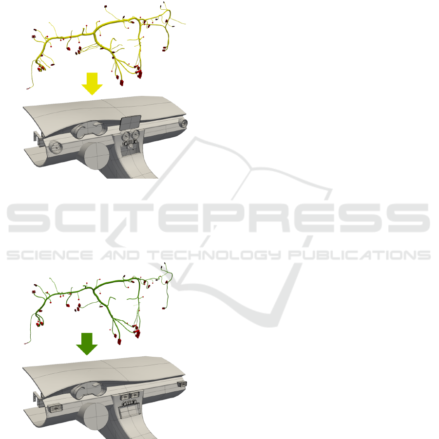
The challenge of wire harness design in industry is
hereby not the only the overall length and cost of cop-
per, but due to the mass customization a huge number
of customer options become possible and need to be
manufactured. This means that the wire harness in the
premium segment of the automotive industry mutated
to a wire harness design with “lot-size 1”.
Figure 10: Automated harness routing with navigation sys-
tem and round air outlets (Eheim et al., 2021).
The first harness shown in figure 10 differs to the
second harness shown in figure 11 by the two differ-
ent electric components (navigation system versus ra-
dio) which results in a subset of different connections
Figure 11: Automated harness routing with radio instead
navigation and square air outlets (Eheim et al., 2021).
(with positions and tangents) for the harness and due
to the different CAD-modeling (round versus square
air outlets) the permissible design space for the har-
ness might be slightly different. This shifts the goal
of the shortest length of the harness more and more
towards the optimal harness module size and the op-
timization of harness manufacturing constraints such
cost and manufacturing integration issues (Karlsson
et al., 2023).
The examples of packing, piping and routing have
been shown here as isolated capabilities. However,
due to the encoding of packing, piping and routing
as software modules inside a graph-based design lan-
guage approach, packing, piping and routing are now
available as engineering services, which is reflected
by the concept of Engineering as a Service (EaaS)
in analogy to the concept of Software as a Service
(SaaS). The combination of such services allows the
creation of complete automated process chains for a
quite complex design process automation.
In most of these automated engineering process
chains, the synthesis power of these algorithms to cre-
ate a solution under the current boundary conditions
is much more important than the knowledge whether
the global optimum of the most lightweight network
connection is in fact achieved, since due to the afore-
mentioned NP-completeness of the engineering task
this global optimum is out of reach for industry-sized
problems anyway.
2.4 AI in Innovation
So far, the presented three search algorithms (PMSO,
SA and A
∗
) used the design is search paradigm based
on the closed-world assumption. This means that all
three algorithms have used a predefined vocabulary
and a predefined set of rules. In consequence, the
scientific question arises to what an extent uncon-
ventional “creative” and new “innovative” solutions
may be generated. In (Riestenpatt gen. Richter and
Rudolph, 2019) these questions are answered as fol-
lows: An
• innovation may be achieved through an unortho-
dox instantiation of an already available vocab-
ulary. As a necessary condition, the parameter
value mutation must be useful in some sense of
the set of employed design goal criteria.
• innovation may be achieved through the extension
of the design language in form of a new vocabu-
lary which brings in and describes some new, for-
merly unknown physical behavior.
This means that similarly to the first possibility, all
three algorithms have used a predefined vocabulary
and a predefined set of rules and all potential instanti-
ations thereof remain in the syntactically permissible
hull of the vocabulary. The solutions belong in this
respect to a closed system.
On Some Artificial Intelligence Methods in the V-Model of Model-Based Systems Engineering
391

There may occur a very special effect in case the
syntactical hull of a vocabulary is larger than its per-
missible semantical hull (Riestenpatt gen. Richter and
Rudolph, 2019). In such a case, the occurring uncon-
ventional instantiation is either meaningless or gives
birth to a new semantic meaning by the mechnism
of emergence. The second possibility of innovation
above by adding a new vocabulary to the known vo-
cabulary set has in this respect the very same effect,
but relies on the enlargement of the vocabulary from
the outside in an open system.
Large Language Models (LLMs) represent in this
respect a new AI technique which opens new perspec-
tives. However, at least for the near future, the un-
derlying method of word embeddings (Gomez-Perez
et al., 2020) in LLMs is however not yet well un-
derstood nor stable (Arseniev-Koehler, 2022), but the
potential to have an information processing system
which is capable to be permanently extended offers a
clear research perspective and shows a huge potential
for future industrial applications of all kinds.
2.5 The Potential of AI in Design
Beyond the three above show-cases of AI techniques
shown in the design of the physical architectures of
aerospace or automotive systems and products, AI
techniques possess a huge potential in design appli-
cations. The fact that the currently known state of AI
doesn’t represent a theory in closed form but looks
more like a dispersed and fragmented set of different
methods and divers tools is hereby not necessarily a
disadvantage. This is due to the fact that the activity
of engineering design as it is performed by humans,
follows a pattern of divergence and convergence.
In the phase of divergence, a set of multiple to
many design alternatives is created. In this phase, it
is most important to increase the number of poten-
tial design solutions in order to “widen the solution
space”. This search for alternative design solutions
seems to be quite opportunistic, since the true source
of these new alternatives doesn’t really matter, even
blind search using randomized algorithmic elements
are accepted as long as is serves the purpose of creat-
ing something new and potentially useful.
In the phase of convergence, the emphasis is on
the simulation, analysis and evaluation of the design
alternatives in order to establish a ranking to select
the best. In this phase, first principles play a central
role in order to be capable to compute and prove the
correct behavior of the design in order to justify the
evaluation and selection of the chosen design solution
despite the fact that the origin of this design alterna-
tive might be the result of a stochastic algorithm.
In reference to the already explained and digital
machine-executable V-model of MBSE shown in fig-
ure 4 the potential for AI techniques in design be-
comes now fully apparent, since the subsequent cre-
ation of the functional system architecture, the logical
system architecture and the physical system architec-
ture marks the presence of three subsequent divergent
and convergent design phases for the creation, synthe-
sis, simulation, analysis, evaluation and final selection
of one design alternative out of many in order to pro-
ceed to the next design phase. In each of these three
system architecture design phases, AI techniques of
various kinds might be useful.
There exists a huge interest in design to make also
the divergent phase accessible to methods based on
first principles to minimize the effort of creating new
designs. This means as a consequence, that the better
these AI methods and tools are mathematically ana-
lyzed and understood, the more they loose their origi-
nal character as AI black boxes and become a member
in the methods repertoire of the natural sciences.
3 CONCLUSIONS
An AI-enhanced machine-executable V-Model for
MBSE for the “intelligent” automation of packing,
piping and routing in real-world engineering design
tasks is shown. The integration of artificial intel-
ligence search techniques is achieved by means of
graph-based design languages.
Graph-based design languages consist of a vocab-
ulary which form ontologies, a set of rules and a pro-
duction systems which contains the definition of the
rule sequence. Graph-based design languages can be
automatically compiled by a compiler into various ex-
ecutable domain-specific language models such as the
CAD-models shown. Three different AI search meth-
ods (PMSO, SA and A
∗
) have been illustrated with
industrial examples such as the automated packing,
piping and routing of subsystems during the physical
system architecture design phase. Due to the fact that
the behavior of these AI techniques is often not fully
understood, their use is often driven by opportunism
as long as it serves the purpose.
Furthermore, the notion of closed and open sys-
tems has been shortly introduced and discussed to un-
derstand the different underlying assumption of emer-
gence, which differentiates a closed system from an
open system. The most recent implementations of
such open systems in the form of LLMs are however
far too little understood to entirely understand their
behavior, despite the fact that LLMs seem to be capa-
ble to push AI to the next level of open systems.
MBSE-AI Integration 2024 - Workshop on Model-based System Engineering and Artificial Intelligence
392

ACKNOWLEDGEMENTS
The author thanks the two anonymous reviewers for
their detailed comments which helped to improve the
readability of the paper.
The author is the head of the Design Theory
and Similarity Mechanics Group at the University of
Stuttgart, Germany, and supervises in this function the
PhD research works in the group. All the various re-
sults of the different packing, piping and routing al-
gorithms shown are parts of these PhD works in the
research group and are cited accordingly.
The funding of parts of this research by the Eu-
ropean Commission in the framework of the H2020
CS2 project PHAROS (see https://cordis.europa.eu/
project/id/865044 for details), the German ministry
for education and research in the context of the MA-
NUNET project FORTIFIER in the research pro-
gram “Future of Value Creation” (grant number
MNET20/ICT-3763) and of the ITEA3 project IDE-
ALISM (see https://itea4.org/project/idealism.html
for details) is greatly acknowledged.
The findings in this research do not necessarily re-
flect the opinion of the funding agencies.
REFERENCES
Arseniev-Koehler, A. (2022). Theoretical foundations and
limits of word embeddings: What types of meaning
can they capture? Department of Sociology, Univer-
sity of California, Los Angeles.
Cagan, J., Shimada, K., and Yin, S. (2002). A survey of
computational approaches to three-dimensional layout
problems. Computer-Aided Design, 34(8):597–611.
Eheim, M., Kaiser, D., and Weil, R. (2021). On automa-
tion along the automotive wire harness value chain.
In Weißgraeber, P., Heieck, F., and Ackermann, C.,
editors, Advances in Automotive Production Technol-
ogy – Theory and Application, pages 178–186, Berlin.
Springer.
Gomez-Perez, J. M., Denaux, R., and Garcia-Silva, A.
(2020). Understanding Word Embeddings and Lan-
guage Models, pages 17–31. Springer International
Publishing, Cham.
Hahn, N. and Rudolph, S. (2023). Digitale Durchg
¨
an-
gigkeit, Konsistenz und Interoperabilit
¨
at im Produkt-
lebenszyklus mit graphenbasierten Entwurfssprachen
(in German). In VDI Automation Congress, pages
443–458, Baden-Baden. VDI Verlag.
IILS mbH (2023). Design Cockpit 43
®
. https://www.iils.de.
Karlsson, T.,
˚
Ablad, E., Hermansson, T., Carlson, J., and
Tenf
¨
alt, G. (2023). Automatic cable harness layout
routing in a customizable 3D environment. Computer-
Aided Design, page 14.
Kirkpatrick, S., Gelatt, C. D., and Vecchi, M. P. (1983).
Optimization by simulated annealing. Science,
220(4598):671–680.
Leung, J. Y.-T., Tam, T. W., Wong, C., Young, G. H.,
and Chin, F. Y. (1990). Packing squares into a
square. Journal of Parallel and Distributed Comput-
ing, 10(3):271–275.
Neumaier, M., Kranemann, S., Kazmeier, B., and Rudolph,
S. (2022). Automated piping in an Airbus A320
landing gear bay using graph-based design languages.
Aerospace, 9(3).
Pahl, G. and Beitz, W. (1996). Engineering Design. A Sys-
tematic Approach. Springer, Berlin, Germany.
Riestenpatt gen. Richter, M. and Rudolph, S. (2019). A
scientific discourse on creativity and innovation in the
formal context of graph-based design languages. In
13th Anniversary “Heron Island” Conference Work-
shop on Computational and Cognitive Models of Cre-
ative Design, (HI‘19), pages 1–19.
Rudolph, S. (2011). On design process modelling aspects
in complex systems. In 13th NASA-ESA Workshop
on Product Data Exchange (PDE 2011), pages 1–28,
Cypress, California, USA. National Aeronautics and
Space Administration.
Rudolph, S. (2023). Digital continuity, consistency and
interoperability along the product life-cycle using
graph-based design languages. In Global Product
Data Interoperability Summit (GPDIS 2023), pages
1–24, Phoenix, Arizona, USA. GPDIS.
Sahni, S. and Bhatt, A. (1980). The complexity of de-
sign automation problems. In Proceedings of the
17th Design Automation Conference, DAC ’80, page
402–411, New York, NY, USA. Association for Com-
puting Machinery.
Schmidt, J. and Rudolph, S. (2016). Automation opportu-
nities in the conceptual design of satellite propulsion
systems. In Systems Engineering and Concurrent En-
gineering for Space Applications (SECESA), pages 1–
8, Nordwijk, Netherlands. European Space Agency.
Schopper, C. (2023). Generative Layout- und Packingver-
fahren im digitalen Produktentwurf (in German). PhD
Thesis, University of Stuttgart.
Simon, H. A. (1969). The Sciences of the Artificial. MIT
Press, Cambridge, MA.
Voss, C., Petzold, F., and Rudolph, S. (2023). Graph trans-
formation in engineering design: an overview of the
last decade. Artificial Intelligence for Engineering De-
sign, Analysis and Manufacturing, 37:1–17.
Walter, B., Kaiser, D., and Rudolph, S. (2018). Machine-
executable model-based systems engineering with
graph-based design languages. In Bonjour, E., Krob,
D., Palladino, L., and Stephan, F., editors, Com-
plex Systems Design & Management, pages 203–210,
Cham. Springer International Publishing.
Walter, B., Kaiser, D., and Rudolph, S. (2019). From
manual to machine-executable model-based systems
engineering via graph-based design languages. In
Proceedings of the 7th International Conference on
Model-Driven Engineering and Software Develop-
ment, MODELSWARD 2019, page 201–208.
On Some Artificial Intelligence Methods in the V-Model of Model-Based Systems Engineering
393
