
Development of an Affordable EMC Immunity Assessment Setup Using
Direct Power Injection for Biosignals Instrumentation: Application to
ECG Monitoring
Tiago Nunes
1,3 a
, Hugo Pl
´
acido da Silva
1,2 b
and Hugo Gamboa
1,3 c
1
PLUX Wireless Biosignals, Lisbon, Portugal
2
Instituto de Telecomunicac¸
˜
oes, Lisbon, Portugal
3
NOVA School of Science and Technology, Almada, Portugal
Keywords:
Electromagnetic, Interference, Immunity, EMC.
Abstract:
The increasing number of connected electronic devices in our daily lives contributes to a more dense electro-
magnetic environment, increasing the challenge of resilience to electromagnetic interference. This is particu-
larly concerning when the context is healthcare and the devices currently used to assess one’s health condition.
It is crucial that the development of new devices for biosignals acquisition takes into consideration the elec-
tromagnetic compatibility of the device from an early stage of the design. In this paper, a methodology to
assess the immunity of a device based on direct power injection is proposed. We describe the setup used and
the PCBs designed for the specific case of an ECG acquisition device. The validation of the setup is made
with two scenarios previously evaluated in anechoic environment. We show that with the proposed setup we
observe the same effects as in anechoic environment.
1 INTRODUCTION
The increasing number of electronic devices available
to the masses, and especially those capable of wire-
less communication, is the source behind many elec-
tromagnetic disturbances (Alaeldine et al., 2008).
This trend tends to increase, as the number of con-
nected devices is growing everyday. In fact, recent
reports have shown that in the last five years the num-
ber of connected Internet of Things (IoT) devices has
doubled. This number is expected to keep increasing
yearly in the coming years (Sinha, 2023; Sujay Vail-
shery, 2023).
Many of these devices are wearables, i.e., devices
that are designed to be worn embedded in clothing or
used as accessories, such as smartwatches or wrist-
bands, capable of acquiring different biosignals and
used increasingly in medical applications. Be it in
hospitals or at home, the environment in which a med-
ical device is placed is no longer a controlled one,
and it is becoming increasingly harsh from an Elec-
tromagnetic Interference (EMI) point of view.
a
https://orcid.org/0000-0001-5195-6668
b
https://orcid.org/0000-0001-6764-8432
c
https://orcid.org/0000-0002-4022-7424
Their use is only expected to increase as we transi-
tion to an era of digital medicine. Therefore, it is cru-
cial that good Electromagnetic Compatibility (EMC)
design practices are put in place during the develop-
ment of biomedical devices (Smuck et al., 2021; Lu
et al., 2020).
Ensuring resilience to electromagnetic interfer-
ence when designing a new device is key to make sure
the system will be compliant with the standards, and
immune to the noise in its intended use environment.
In fact, one of the most common causes for Printed
Circuit Board (PCB) redesign are EMC related issues.
While it is true that the smaller form factor of
today’s Integrated Circuits (IC) makes them intrinsi-
cally less prone to be disturbed by radiated and in-
duced disturbances, their placement in a PCB can in-
crease susceptibility as the traces leading to the IC can
pick up noise and carry it to the pins of the compo-
nent (Lavarda et al., 2017; Lavarda and Deutschmann,
2015; Jian-fei et al., 2011). Hence, good practices
when designing a new PCB are essential to ensure a
good performance from the device.
Typically, embedded applications, independently
of the domain of application rely heavily on a micro-
controller. This is arguably the most important ele-
82
Nunes, T., Plácido da Silva, H. and Gamboa, H.
Development of an Affordable EMC Immunity Assessment Setup Using Direct Power Injection for Biosignals Instrumentation: Application to ECG Monitoring.
DOI: 10.5220/0012588900003657
Paper published under CC license (CC BY-NC-ND 4.0)
In Proceedings of the 17th International Joint Conference on Biomedical Engineering Systems and Technologies (BIOSTEC 2024) - Volume 1, pages 82-87
ISBN: 978-989-758-688-0; ISSN: 2184-4305
Proceedings Copyright © 2024 by SCITEPRESS – Science and Technology Publications, Lda.

ment of the entire system since it makes the device
achieve its main purpose. However, the microcon-
troller in itself is not able to fulfill the device pur-
pose without a series of other modules such as power,
communication and, in the specific case of a medical
application, a biomedical sensor specifically designed
for the physiological signal of interest in that particu-
lar equipment.
Traditionally, these systems have been using
PCBs to assemble the components and interconnected
these modules via traces.It is important to mention
that all of the aforementioned elements, from the in-
dividual components to the PCB that brings them to-
gether, are susceptible to electromagnetic interference
which can disturb the system.
Several studies have tried to demonstrate this fact
by analyzing the various potential coupling victims
using the Direct Power Injection (DPI) method.
Established by the standard IEC62132-4 (IEC,
2006), DPI is one of the most reproducible methods
to evaluate a systems susceptibility to electromagnetic
interference. It allows to characterize the immunity
of a system in the presence of RF disturbances by in-
jecting them capacitively in the circuit (Chang et al.,
2013). It is widely adopted as it allows for rapid and
easy assessment of a PCB. In fact, as soon as the first
prototypes are ready, DPI can be immediately per-
formed in a simple and intuitive way. This is possi-
ble as it doesn’t require advanced knowledge on EMC
(Pues and Pissoort, 2012; Miropolsky and Frei, 2011).
In a study carried out by (Dai et al., 2021), the
conducted immunity of a microcontroller was inves-
tigated exposing the IC to a continuous-wave electro-
magnetic interference using DPI. They observed the
conditions under which the IC failed and verified with
an electron microscope the damage inflicted.
In (Jian-fei et al., 2011), the authors were in-
terested in evaluating the susceptibility of a Low
Dropout Voltage regulator (LDO) using direct power
injection. They demonstrated via simulation and also
experimentally how a Radio Frequency (RF) distur-
bance injected using DPI generates an offset in the
output of the LDO.
In other works, the effects of electromagnetic in-
terference in amplifiers were investigated using DPI
to inject a disturbance through the ground plane and
output pins of amplifiers in various topologies and
configurations, such as the consequences of distur-
bances on precision voltage references (Lavarda et al.,
2017; Deutschmann and Winkler, 2023; Richelli
et al., 2020; Richelli et al., 2016; Richelli et al., 2017).
All of the modules mentioned above and previ-
ously investigated are key elements for a biomedical
system to operate. It is of paramount importance that
all these matters are taken into consideration during
the design of a new device. While anechoic chambers
are not easily accessible to everyone, and in partic-
ular to Small and Medium Enterprises (SME)s, DPI
testing can be easily and affordable to conduct.
In this paper we present a system developed to
evaluate the behavior of a device designed to acquire
biosignals when in the presence of a disturbing sig-
nal. Our solution provides a simple approach to as-
sess EMI immunity for SMEs and researchers who
do not have the means or access to more complex and
expensive solutions.
For this we use the DPI method as the noise in-
jection method, and a simulated Electrocardiogram
(ECG) as desired signal; in section 2 we present the
equipment used for this setup; in section 3 we present
two examples of application using this assessment
method; and in section 4, we outline the main con-
clusions and future work prospects.
2 MATERIALS AND METHODS
The purpose of this setup is to input a simulated ECG
signal for the Device Under Test (DUT) to acquire
while a disturbance is injected in the system capac-
itively using DPI. To fulfill these requirements, two
PCBs were designed: one with the purpose of simu-
lating a differential ECG signal for the DUT to sample
and another one to generate the interference to be in-
jected in the system. The entire setup is placed inside
a metallic enclosure to provide shielding against ex-
ternal electromagnetic noise. The 3D models of the
two PCBs are presented in figures 1 & 2.
2.1 ECG Signal Simulator
To generate the ECG signal, an Analog Discovery 2
arbitrary waveform generator was used. This device
featuring two Digital to Analog Converter (DAC) is
able to generate common signals, such as sinusoidal
waves, but also arbitrary signals with a 14-bit reso-
lution and voltages up to 5 V. We make use of this
feature to create the disturbing signal and the ECG
signal: we use MATLAB 2023b to create the differ-
ent signals that we want to test on the setup, and using
a toolbox by Digilent we are able to send the signals
directly to the signal generator where they are con-
verted into analog single-ended signals.
Naturally, the ECG signal has a very low ampli-
tude (+/- 1 mV) and for that reason, ECG sensors have
a very high amplification gain (+/- 60 dB)(Singh et al.,
2012). Therefore, we need to create a very low am-
plitude signal for both the ECG signal and the distur-
Development of an Affordable EMC Immunity Assessment Setup Using Direct Power Injection for Biosignals Instrumentation: Application
to ECG Monitoring
83

Figure 1: PCB designed to convert a simulated single ended
ECG signal into a differential one.
bance. When generating low amplitude values with
this generator, only the Least Significant Bits of the
DAC are used, rendering a very low resolution sig-
nal. To overcome this, we use all the DAC’s 14 bits to
generate a high resolution signal and we decrease the
amplitude using a voltage divider with the designed
PCB’s.
For the ECG signal, besides the need to reduce the
amplitude, we also need to convert the single ended
signal into a differential one for the sensor to acquire
it. The IC used for this purpose is th LTC6363. The
two outputs of this module will be centered over a
reference voltage provided by the ECG sensor. The
PCB presents snap connectors for the DUT to plug in
by the means of electrode lead wires.
2.2 Direct Power Injection Board
For this specific application, a PCB was carefully de-
signed with the purpose of delivering the disturbance
to the DUT. This PCB, presented in Figure 2, is used
to connect the signal generator to the DUT, in partic-
ular the ECG sensor. This kind of sensor presents a
high gain on its amplification stage as biosignals have
a very low amplitude. For that reason, when inject-
ing a noise signal in this port, if the amplitude is too
elevated, the amplifier will saturate and no particular
conclusions can be deduced from the tests.
This particular setup is intended to be used with
different types of disturbances while the effects are
evaluated in the time domain by analyzing the influ-
ence they have on the ECG signals. To be able to see
the effect of a small disturbance on the ECG signal,
one needs to reduce the amplitude of the disturbance
being generated by the signal generator. We use the
same method as for the ECG signal generator, i.e., we
make use of the full scale of the DAC to produce a
high resolution signal and then decrease its amplitude
with an voltage divider.
2.3 Considerations for PCB Design
During the design phase of any PCB in general, and
PCBs for electromagnetic compliance assessment in
Figure 2: PCB for direct power injection.
particular, it is important to make sure that they oper-
ate with no major disturbances from the surroundings
nor from the PCB itself. In the development of these
PCBs, however simple they might be, several tech-
niques were used in order to minimize interference.
4-layer PCB. In the earliest stage of the design of
the PCB’s, the decision was made to use a 4-layer
PCB instead of a more common 2 layer one. While
the complexity is slightly increased when the num-
ber of layers increase, the benefits extracted from it
compensate the effort put into the design of the prod-
uct. Opting for a 4-layer PCB not only provides more
flexibility for routing traces but it also, and more im-
portantly, allows for signal integrity optimization with
the use of power and ground planes which effectively
reduce crosstalk and electromagnetic interference. In
the example of our application, layers were organized
as follows:
• Layer 1 is where all the components are placed.
Small traces connecting pins close to each other
are routed directly on this layer. Pins spaced far
from each other are routed through Layer 3.
• Layer 2 and Layer 4 are ground planes. Layer 2
creates a stable ground reference for all the ele-
ments of the PCB even in the higher frequencies,
where a simple ground trace would not be suffi-
cient (Armstrong, 1999). The two ground planes,
top and bottom are connected though a dense net-
work of vias. In combination with via fencing,
this configuration turns the PCB into a Faraday
cage, in which signals that can penetrate the struc-
ture are limited by the distance between vias.
• Layer 3 is used to route the traces connecting pins
placed away from each other. Additionally this
plane serves as a power plane providing power di-
rectly to the power pin of any component through
a via. This plane is placed in the middle of
two ground planes ensuring shielding of both the
power connections and traces routed in it.
Via Spacing and Fencing. The downsize in the
form factor of components has lead to increasingly
BIODEVICES 2024 - 17th International Conference on Biomedical Electronics and Devices
84
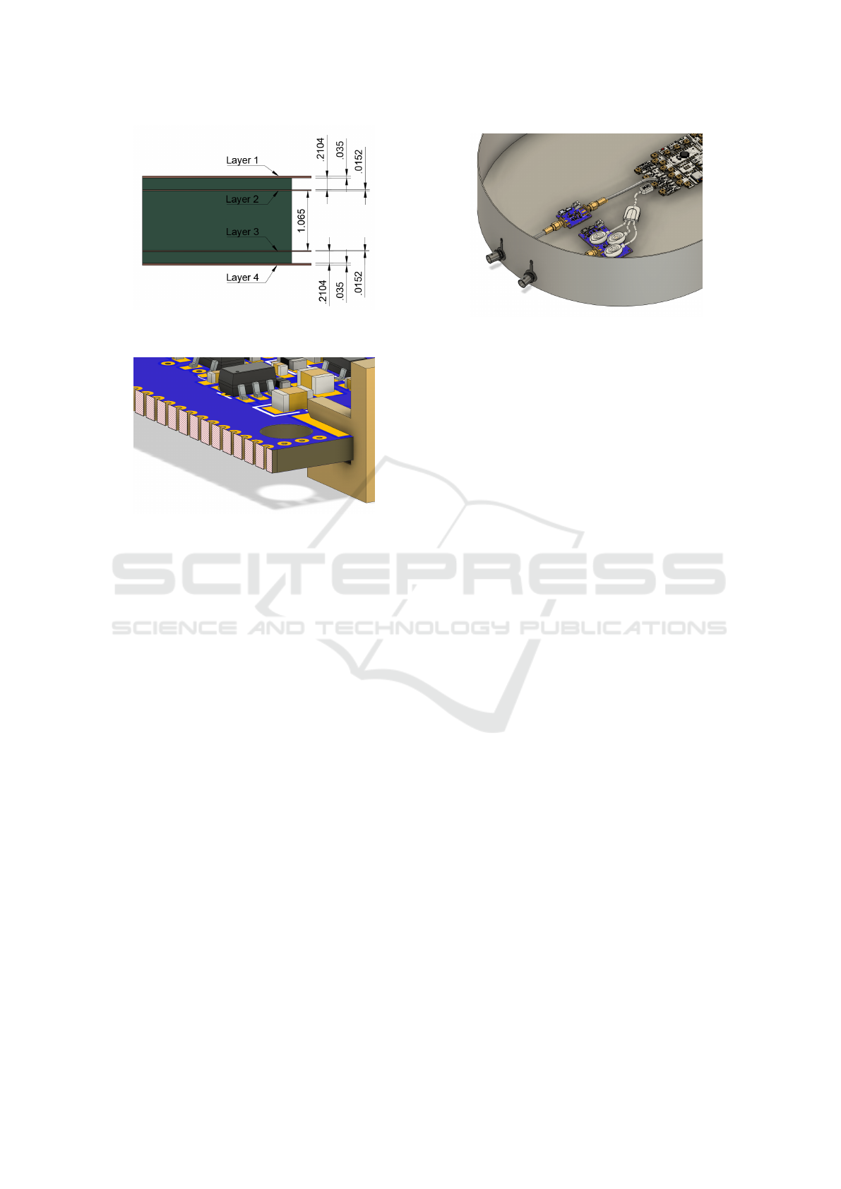
Figure 3: Cross section of the PCB showing the different
layers that compose it. All units are in millimeters.
Figure 4: Fencing used around the PCB’s to prevent radially
propagated electromagnetic emissions.
complex and denser layouts in PCBs, which in turn
leads to signal integrity problems such as crosstalk.
To ensure a good connection between the top and bot-
tom ground planes, as well as to prevent radially prop-
agated electromagnetic emissions through the PCB’s
edges, a dense grid of vias is used. Additionally, it is
also common practice to use via fencing as a measure
of preventing radially propagated energy from the
sides of a PCB. In fact, this constitutes one of the main
sources of radiated emissions in a PCB. These propa-
gate thanks to pseudo-waveguides formed by ground
and/or power planes leading to emissions from the
PCB’s edge (Lindseth, 2016; Suntives et al., ).
Power Supply Decoupling. The power supply
must be as stable as possible. As demonstrated by
previous works mentioned in Section 1, voltage refer-
ences and power/ground connections are susceptible
to inducing disturbances on the device components.
To be sure that the power lines are as stable as pos-
sible, decoupling capacitors are used to stabilize the
supply and avoid high frequency noise. Their place-
ment on the PCB is equally important. These must be
placed as close as possible to the pins of the power
supply of the components.
Coaxial Connections. The disturbance and simu-
lated ECG signals created by the signal generator
Figure 5: Enclosure used to protect the setup.
must arrive at the PCB undisturbed. The best way to
do so is by using coaxial cables. Typically the signal
generator’s output is, by default, a coaxial connection
BNC. Therefore, by applying a SMA connector to the
PCB side, we can use a coaxial cable to connect the
two devices. This is achieved by using a BNC to SMA
cable ensuring that the signal produced by the signal
generator arrives uncorrupted at the PCB.
3 RESULTS
The validation of the setup was performed with time
domain measurements using a BITalino (r)evolution
(PLUX Wireless Biosignals, Lisbon, Portugal) as
DUT. This device was designed to acquire multiple
biomedical signals (in particular, the ECG) and trans-
mit them via Bluetooth to a computer nearby.
A simulated ECG signal is generated with the
setup previously presented and then sampled by the
DUT. The latter, transmits the signal to a nearby com-
puter where the signal can be visualized and stored for
further post processing. The DPI board injects then a
signal in one of the pins of the board while the acqui-
sition is ongoing. The effects of the disturbance are
evaluated on the signal acquired.
The system itself is quite sensitive to the inher-
ent noise from the mains supply at 50 Hz. Such a
signal can be of an order of magnitude big enough
to completely mask all the other disturbances and
even the ECG signal itself. In an attempt to con-
tain such effects and focus on the disturbance be-
ing injected, we placed the setup inside a metallic
box. Although the container is not completely sealed,
the biggest apertures are small enough to prevent the
50 Hz noise from arriving at the DUT while allowing
for Bluetooth communication to be established with
the nearby computer.
This enclosure was fitted with BNC feedthroughs
so that the signals from the waveform generator could
be delivered to the PCBs using fully shielded cables
Development of an Affordable EMC Immunity Assessment Setup Using Direct Power Injection for Biosignals Instrumentation: Application
to ECG Monitoring
85

Figure 6: Acquired ECG in the presence of a disturbance
modulated at 1.1 kHz.
thus preventing any interference from coupling to the
signals. On the inside, an SMA cable carries the sig-
nal from the generator to each PCB as illustrated by
Figure 5. Finally, the electrode lead wires connect to
the PCB via the snap connectors and the disturbance
is injected using an SMA probe.
3.1 Use Cases
Case 1. In standardized test procedures such as
IEC61000-4-3, the disturbing signal modulates the
carrier signal using a 1 kHz sine wave modulated at
80% depth (CENELEC, 2015). In previous works
(Bastian et al., 2023), it has been demonstrated, by
changing the modulating frequency with small incre-
ments, that when the modulating frequency matches
the sampling rate some failure modes are missed.
Here, we attempt to reproduce the same phenom-
ena by injecting a disturbance modulated in amplitude
at 80% with a carrier of 1 kHz. This frequency is then
incremented by 0.1 kHz and the effects are observed;
in Figure 6 we can clearly see the moment in which
the signal gets disturbed. At this point, the frequency
of the carrier shifts from a multiple of the sampling
rate to value slightly different.
Case 2. Another example used to validate the setup
consisted in injecting a modulated signal with a low
frequency AM modulation, in particular a 1 kHz sine
wave modulated at 20 Hz with a 80% depth. The ef-
fects of such a signal on the same device for biomed-
ical acquisition have previously been demonstrated
in an anechoic chamber with radiated interference
(Nunes et al., 2023).
We try to reproduce these effects by injecting a
similar signal using DPI. In our setup, while the DUT
was acquiring the ECG signal, the DPI board injected
the disturbing signal in the input pin of the ECG am-
Figure 7: Acquired ECG in the presence of a disturbance
modulated at 20 Hz.
plifier. On the computer placed nearby, the signal be-
ing acquired was registered and is presented in Fig-
ure 7. It is possible to see the moment in which the
disturbance is activated; the effects of a disturbance
on the ground plane are immediately visible on signal
being acquired.
4 CONCLUSIONS
Assessment of electromagnetic compatibility is a cru-
cial step to guarantee a product behaves as expected,
and to be able to certify the device before putting
it in the market. Typical testing is performed in an
anechoic environment, which is not always accessi-
ble small and medium enterprises and/or students and
researchers. A more affordable method to assess elec-
tromagnetic immunity of devices is DPI.
We proposed a solution based on the DPI method-
ology, in which a device for biomedical acquisition
can be tested against conducted immunity. Two PCBs
were developed providing a simulated biosignal for
the device to acquire and a disturbing signal to inter-
fere with the first.
This approach provides students, researchers and
SMEs with an affordable solution to verify and vali-
date devices for biosignals acquisition against electro-
magnetic interference from an early stage of the de-
sign phase as it eliminates the need for expensive and
specialized solutions such as anechoic environments.
Our system was validated reproducing tests previ-
ously conducted leading to the same conclusions.
In future works, it is foreseeable the addition of
frequency analysis as a complement to better under-
stand how the different disturbances affect the DUT
while performing an acquisition.
BIODEVICES 2024 - 17th International Conference on Biomedical Electronics and Devices
86

ACKNOWLEDGEMENTS
The research leading to these
results has received funding
from the European Union’s EU
Framework Programme for Re-
search and Innovation Horizon
2020 under Grant Agreement No.
955.816. Project website: https://eternity-project.eu
REFERENCES
Alaeldine, A., Perdriau, R., Ramdani, M., Levant, J.-L., and
Drissi, M. (2008). A Direct Power Injection Model
for Immunity Prediction in Integrated Circuits. IEEE
Trans. on Electromagnetic Compatibility, 50(1):52–
62.
Armstrong, M. K. (1999). PCB design techniques for
lowest-cost EMC compliance. Part 1. Electron-
ics & Communication Engineering Journal,
11(4):185–194.
Bastian, G. G., Pinto Nunes, T., Qu
´
ılez, M., Fern
´
andez-
Chimeno, M., and Silva, F. (2023). Analysis of the
Effect of Deviated Modulating Signal Characteristics
on the Susceptibility of a Small Medical Device. In
Proc. of Intl. Symp. on Electromagnetic Compatibility
– EMC Europe 2023, pages 1–6.
CENELEC (2015). Medical Electrical Equipment—Part 1–
2: General Requirements for Basic Safety and Essen-
tial Performance—Collateral Standard: Electromag-
netic Disturbances—Requirements and Tests.
Chang, Y.-C., Hsu, S. S. H., Chang, Y.-T., Chen, C.-K.,
Cheng, H.-C., and Chang, D.-C. (2013). The direct
RF power injection method up to 18 GHz for inves-
tigating IC’s susceptibility. In Proc. of the 9th Intl.
Workshop on Electromagnetic Compatibility of Inte-
grated Circuits (EMC Compo 2013), pages 167–170.
Dai, S., Lu, X., Zhang, Y., Liu, L., and Fang, W. (2021).
Electromagnetic Conductive Immunity of a Micro-
controller by Direct Power Injection. In Proc. of 6th
Intl. Conf. on Integrated Circuits and Microsystems
(ICICM), pages 280–284.
Deutschmann, B. and Winkler, G. (2023). Characterizing
the Electromagnetic Immunity of Operational Ampli-
fiers based on EMIRR and DPI. In Proc. of Intl.
Symp. on Electromagnetic Compatibility – EMC Eu-
rope 2023, pages 1–4.
IEC (2006). IEC 62132-4:2006 Integrated circuits - Mea-
surement of electromagnetic immunity 150 kHz to 1
GHz - Part 4: Direct RF power injection method.
Jian-fei, W., Sicard, E., Ndoye, A. C., Lafon, F., Jian-cheng,
L., and Rong-jun, S. (2011). Investigation on DPI ef-
fects in a low dropout voltage regulator. In 2011 8th
Workshop on Electromagnetic Compatibility of Inte-
grated Circuits, pages 153–158.
Lavarda, A. and Deutschmann, B. (2015). Direct power in-
jection (DPI) simulation framework and postprocess-
ing. In Proc. of IEEE Intl. Symp. on Electromagnetic
Compatibility - EMC Europe, pages 1248–1253.
Lavarda, A., Deutschmann, B., and Haerle, D. (2017). En-
hancement of the DPI method for IC immunity char-
acterization. In Proc. of 11th Intl. Workshop on the
Electromagnetic Compatibility of Integrated Circuits
(EMCCompo) 2017, pages 178–183.
Lindseth, W. (2016). Effectiveness of PCB perimeter Via
fencing: Radially propagating EMC emissions reduc-
tion technique. In Proc. of IEEE Intl. Symp. on Elec-
tromagnetic Compatibility - EMC Europe 2016, pages
627–632.
Lu, L., Zhang, J., Xie, Y., Gao, F., Xu, S., Wu, X., and
Ye, Z. (2020). Wearable Health Devices in Health
Care: Narrative Systematic Review. JMIR mHealth
and uHealth, 8(11):e18907.
Miropolsky, S. and Frei, S. (2011). Comparability of RF im-
munity test methods for IC design purposes. In 2011
8th Workshop on Electromagnetic Compatibility of In-
tegrated Circuits, pages 59–64.
Nunes, T. P., Qu
´
ılez, M., Fern
´
andez-Chimeno, M., Silva, F.,
and da Silva, H. P. (2023). Stage-by-stage evaluation
of a biomedical system regarding its electromagnetic
susceptibility. In Proc. of Intl. Symp. on Electromag-
netic Compatibility – EMC Europe 2023, pages 1–6.
Pues, H. and Pissoort, D. (2012). Design of IEC 62132-4
compliant DPI test Boards that work up to 2 GHz. In
Proc. of IEEE Intl. Symp. on Electromagnetic Com-
patibility - EMC EUROPE 2012, pages 1–4.
Richelli, A., Colalongo, L., and Kovacs-Vajna, Z. (2020).
EMI Susceptibility of the Output Pin in CMOS Am-
plifiers. Electronics, 9(2):304.
Richelli, A., Colalongo, L., Toninelli, L., Rusu, I., and Red-
out
´
e, J.-M. (2017). Measurements of EMI suscepti-
bility of precision voltage references. In Proc. of 11th
Intl. Workshop on the Electromagnetic Compatibility
of Integrated Circuits (EMCCompo), pages 162–167.
Richelli, A., Delaini, G., Grassi, M., and Redout
´
e, J.-M.
(2016). Susceptibility of Operational Amplifiers to
Conducted EMI Injected Through the Ground Plane
into Their Output Terminal. IEEE Transactions on
Reliability, 65(3):1369–1379.
Singh, Y. N., Singh, S. K., and Ray, A. K. (2012). Bio-
electrical Signals as Emerging Biometrics: Issues and
Challenges. International Scholarly Research No-
tices, 2012:e712032.
Sinha, S. (2023). State of IoT 2023: Number of con-
nected IoT devices growing 16% to 16.7 billion glob-
ally. Technical report.
Smuck, M., Odonkor, C. A., Wilt, J. K., Schmidt, N., and
Swiernik, M. A. (2021). The emerging clinical role of
wearables: Factors for successful implementation in
healthcare. npj Digital Medicine, 4(1):1–8.
Sujay Vailshery, L. (2023). IoT connected devices world-
wide 2019-2030. Technical report.
Suntives, A., Khajooeizadeh, A., and Abhari, R. Using via
fences for crosstalk reduction in PCB circuits. In Proc.
of IEEE Intl. Symp. on Electromagnetic Compatibility,
EMC Europe 2006., volume 1, pages 34–37.
Development of an Affordable EMC Immunity Assessment Setup Using Direct Power Injection for Biosignals Instrumentation: Application
to ECG Monitoring
87
