
Dense Light Field Imaging with Mixed Focus Camera
Masato Hirose, Fumihiko Sakaue and Jun Sato
Nagoya Institute of Technology, Nagoya, Japan
Keywords:
Light Field Camera, Variable Focal Lens, Coded Imaging.
Abstract:
In this study, we propose a method for acquiring a dense light field in a single shot by taking advantage of the
sparsity of the 4D light field (LF). Acquiring the LF with one camera is challenging task due to the amount
of data. To acquire the LF efficiently, there are various methods like using micro-lens. However, with these
methods, images are taken using a single image sensor, which improves directional resolution but reduces
positional resolution. In our method, the focal length of the lens is varied, and the exposure is controlled on a
pixel-by-pixel level when capturing a single image to obtain a mixed focus image, where each pixel is captured
at a different focal length. Furthermore, by analyzing the captured image with an image generator that does
not require prior learning, we show how to recover a LF image that is denser than the captured image. With
our method, a high-density LF consisting of 5x5 images can be successfully reconstructed only from a single
mixed-focus image taken under a simulated environment.
1 INTRODUCTION
Light field (LF) imaging technology has been attract-
ing attention in recent years along with the popularity
of video content, and various methods using this tech-
nology have been studied. This allows for a variety of
processing that is not possible with ordinary 2D im-
ages.
Cameras that record and store this LF are called
light field cameras, and there are various types de-
pending on the imaging method. The plenoptic
method (Ng, 2005), which uses a lens array, is a typi-
cal method used to acquire LF. Although this method
can acquire LF with a single camera, it records 4D
LF with a single image sensor, resulting in a trade-
off between LF directional resolution and LF posi-
tional resolution. Various other methods have also
been proposed for acquiring LF by using different
imaging systems, such as apertures (Marwah et al.,
2013a) (Lin et al., 2013). Recently, a learning-based
method using neural networks to estimate LF from a
small number of images or a single image (Inagaki
et al., 2018), or a method combining a neural network
(Mildenhall et al., 2020) and an improved imaging
system have been proposed. However, there is a prob-
lem that a large amount of training data is required to
use these methods.
In order to obtain LF more efficiently, let us con-
sider its properties. In general, image information is
sparse information, and it is known that efficient rep-
resentation is possible by utilizing this property. Pho-
tography methods that take advantage of this property
have also been proposed (Duarte et al., 2008). LF can
be considered as a set of images taken from various
viewpoints, and thus has the same properties as im-
ages. In particular, if the difference between images
from different viewpoints can be assumed to be small,
LF can be represented more efficiently than image in-
formation. In this study, we focus on this property of
LF and propose a method for acquiring and represent-
ing high-density LF without using training data. For
this purpose, we propose a mixed-focus camera that
combines a lens whose focal length can be changed at
high speed and exposure control on a pixel-by-pixel
basis. We also show how to estimate the dense LF by
analyzing the resulting mixed-focus images. While
the resolution of the light field acquired by the plenop-
tic method is determined by parameters such as the
focal length of the lens, this method can realize adap-
tive shooting according to the scene by changing the
density of the light field acquired for each part of the
image. This is expected to make it possible to acquire
and store light fields more efficiently than before.
786
Hirose, M., Sakaue, F. and Sato, J.
Dense Light Field Imaging with Mixed Focus Camera.
DOI: 10.5220/0012475300003660
Paper published under CC license (CC BY-NC-ND 4.0)
In Proceedings of the 19th International Joint Conference on Computer Vision, Imaging and Computer Graphics Theory and Applications (VISIGRAPP 2024) - Volume 3: VISAPP, pages
786-791
ISBN: 978-989-758-679-8; ISSN: 2184-4321
Proceedings Copyright © 2024 by SCITEPRESS – Science and Technology Publications, Lda.
2 LF IMAGING BY
MIXED-FOCUS CAMERA
2.1 Structure of Mixed-Focus Camera
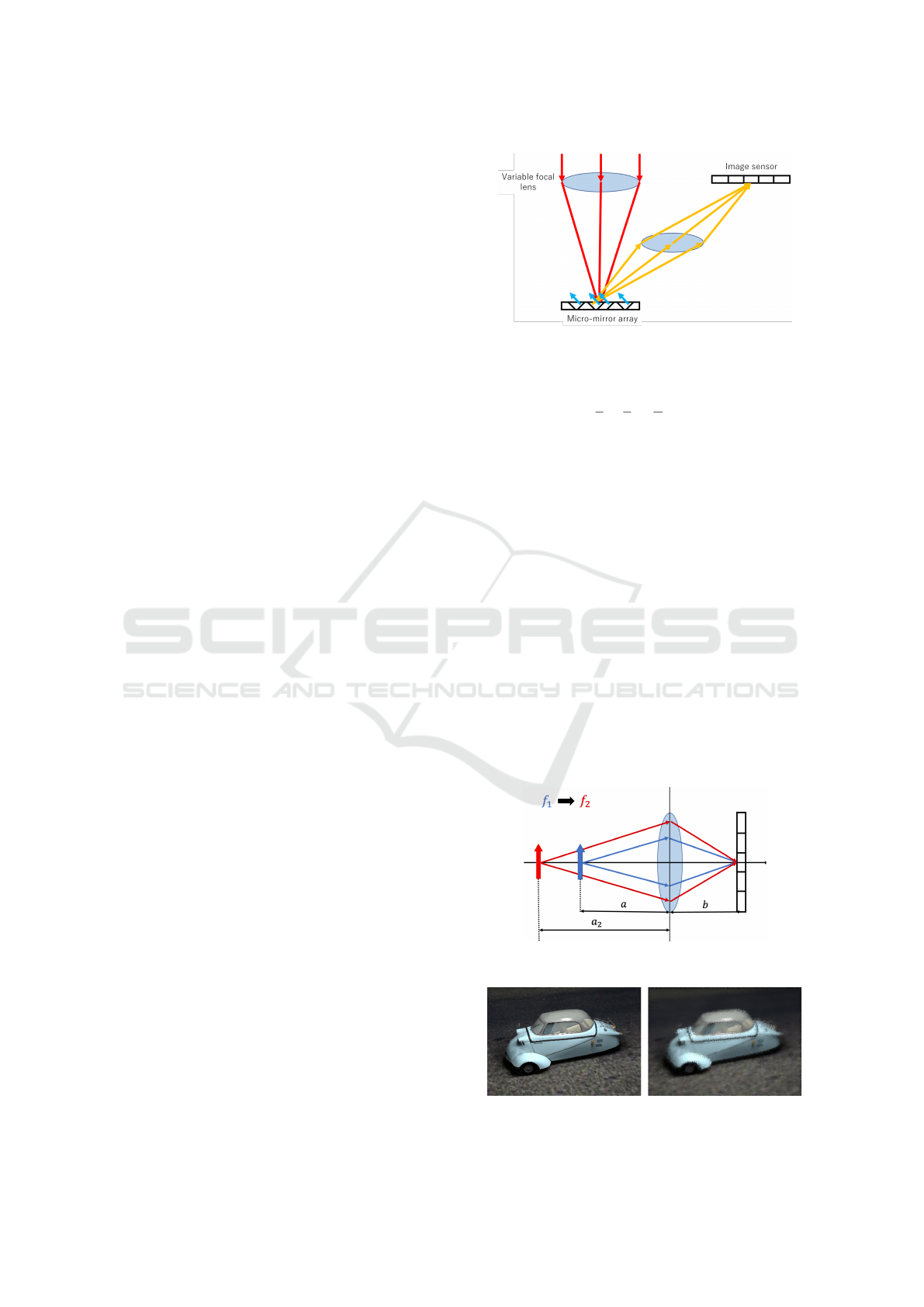
First, the configuration of the mixed focus camera
proposed in this study is described. Fig. 1 shows the
basic structure of the mixed focus camera. As shown
in the figure, in this camera, light rays passing through
the variable focal length lens are reflected by a micro-
mirror before entering the image sensor. The variable
focal length lenses (tunable lenses) that have been on
the market in recent years are capable of changing the
focal length very quickly. This camera can change the
focal length at high speed in sub-frame units during a
single shot. The micro-mirror that reflects light rays
can also realize exposure control in sub-frame units
on a pixel-by-pixel basis. Here, a DLP (Digital Light
Processing) chip equipped with a micro-mirror array
called a DMD (Digital Micro-mirror Device) is used,
and the DMDs on the DLP chip are arranged in an
array, each of which operates independently and can
change the tilt of the mirrors at high speed. Each of
the DMDs on the DLP chip is arranged in an array,
and each operates independently to change the tilt of
the mirror at high speed. This makes it possible to
switch the reflection to the image sensor on or off on
a pixel-by-pixel. Since the DLP can switch ON/OFF
several thousand times per second, it can be used to
control the exposure of each pixel in sub-frame units.
DLP can produce brighter images than LCD methods
such as LCoS because it eliminates the need to use
polarization filters.
Thus, the mixed focus camera proposed in this re-
search can take a single image while changing the fo-
cal length and switching the DLP ON/OFF for each
pixel at the same time. This makes it possible to ob-
tain a mixed-focus image with pixels captured at dif-
ferent focal lengths in a single image. Furthermore,
by performing multiple exposures when capturing an
image, it is possible to capture not only an image cap-
tured under a single focal length, but also an image
that is a mixture of images captured under multiple fo-
cal lengths. This makes it possible to increase the ex-
posure time and capture images that are brighter and
have a higher S/N ratio.
2.2 Mixed-Focus Image
Next, let us consider what kind of image is obtained
when taking a picture while changing the focal length.
If the lens characteristics are ideal, the relation-
ship between the distance a to the object, the distance
b to the image sensor, and the focal length f can be
Figure 1: Structure of mixed-focus camera.
expressed by the lens imaging formula as follows:
1
a
+
1
b
=
1
f
(1)
From this equation, assuming that the distance b be-
tween the lens and the imaging surface is fixed, when
shooting under a certain focal length f
1
, the focal dis-
tance a between the lens and the subject changes to
that corresponding to f
1
. Therefore, the rays of light
captured under f
1
will be the rays indicated by the
blue line in Fig. 2. Therefore, these rays are recorded
at the pixel that was turned on by the DMD control.
If the focal length is changed to f
2
, the focal distance
is changed to a
2
, and the rays of light shown by the
red line in Fig. 2 are recorded. This makes it possible
to record rays of light in different states at the same
pixel. Therefore, by changing the focal length at high
speed during a single shot and simultaneously con-
trolling the exposure of the image at each focal length
using DLP, it is possible to capture various light rays
incident on the scene, i.e., LF. An example of a mixed-
focus image acquired by the proposed LF camera is
shown in Fig. 3.
Figure 2: Effect of focal length changing.
Figure 3: Example of target object and mixed-focus image.
Dense Light Field Imaging with Mixed Focus Camera
787

3 LF IMAGE SYNTHESIS BASED
ON MIXED-FOCUS IMAGE
3.1 Light-Field Reconstruction
The mixed-focus image described above is an image
that contains images taken at different focal lengths
in a single image. Therefore, it can be thought of as
a sparse image taken with only a limited number of
pixels at each focal length and then added together.
In order to estimate LF from such images, this sec-
tion first considers how to estimate LF from multiple
images taken at different focal lengths. For the pur-
pose of simplifying the discussion, we will consider
the case where a 2D LF is acquired as a 1D image
and the 2D LF is estimated from this image.
First, let us consider how to compose an image
from LF. Let L(x, u) denote a ray of light traveling
from a point x on the lens in the direction of u. If the
distance from the lens to the imaging surface is 1 and
the focal length is f , the incident position x
′
of the ray
L(x, u) on the imaging surface can be expressed by the
lens imaging formula as follows:
x
′
= x −
x
f
− u (2)
Assuming that all rays incident on the lens reach the
image sensor, the brightness I(x
′
) observed at x
′
can
be expressed as follows:
I(x
′
) =
Z
x
L(x, −x
′
+ x −
x
f
)dx (3)
This can be regarded as a sub-aperture image L(x, u),
where L(x, u) is the set of rays passing through the
point x on the lens, and the sub-aperture images are
added together by translating them in accordance with
the focal length.
This can be regarded as a sub-aperture image
L(x, u), where L(x, u) is the set of rays passing
through the point x on the lens, and the sub-aperture
images are added together by translating them in ac-
cordance with the focal length. If multiple images
with different focal length f are obtained, the rela-
tionship between the equations can be obtained for
each focal length as a simultaneous Eq. (3). There-
fore, if a larger number of focal length images than
the density of LF to be estimated can be obtained, LF
can be estimated by solving the obtained simultane-
ous equations. However, the number of pixels that
can be captured at each focal length is limited in the
mixed-focus images used in this study. Therefore, a
more efficient method of representing and estimating
LF is needed.
3.2 Light Field Representation
Let us consider LF as a set of sub-aperture images
taken from different viewpoints. In this case, light
uniformly irradiated in all directions from objects in
the scene, i.e., diffuse reflection components, can
be represented by applying a disparity-based view-
point transformation to the image taken from a cer-
tain viewpoint. On the other hand, specular reflec-
tion components and areas hidden by occlusion can-
not be represented by this method. However, since
such components are very rare in general scenes, they
can be represented as sparse images.
In this study, Deep Image Prior (DIP) (Ulyanov
et al., 2018) is used to represent the all-in-focus im-
age. In this DIP, a noise image is input to a neural
network with an Encoder-Decoder structure, and the
image is obtained by optimizing the parameters of the
neural network according to the objective. This en-
ables image inpainting and noise reduction without
the need for training data (Hashimoto et al., 2021). In
the following, the image obtained under the network
parameter θ with noise N input is denoted as I(N, θ).
Thus, estimating the all-in-focus image is equivalent
to finding the optimal θ.
Next, we consider how to apply a viewpoint trans-
formation to the all-in-focus image I(N, θ) to repre-
sent sub-aperture images from different viewpoints.
To perform a viewpoint transformation, the dispar-
ity per pixel between the two images can be esti-
mated, and each pixel can be shifted using this dis-
parity. However, such pixel shifting operations are
highly nonlinear and difficult to use in an optimization
framework. In this study, we use a disparity transfor-
mation method using weight maps (Luo et al., 2018).
In this method, an image I
j
is prepared for the image
to be transformed by shifting the image by T
j
pixels.
Assuming that a mask image W
j
is obtained, where
the disparity of a pixel is set to 1 when the disparity is
T
j
and 0 otherwise, the disparity transformed image I
′
can be generated as follows:
I
′
=
∑
j
diag(W
j
)I
j
(4)
In other words, if W
j
can be estimated appropri-
ately, viewpoint transformation can be applied with-
out shifting pixels. Furthermore, since disparity is a
determined by the depth of an object, a common W
j
can be used for all sub-aperture images by preparing
an appropriate shifted image. In other words, the I
k
d
image at the kth viewpoint can be described as fol-
lows:
I
k
d
=
∑
j
diag(W
j
)I
jk
(5)
VISAPP 2024 - 19th International Conference on Computer Vision Theory and Applications
788

where I
jk
is the image shifted by the quantity image
corresponding to W
j
in the viewpoint k direction. This
method allows the viewpoint transformation to be de-
scribed using only linear operations. As mentioned
above, the weight map is a binary image with a value
of 0 or 1. In this study, however, the weight map is as-
sumed to have continuous values between 0 and 1 to
represent sub-pixel disparity. If the depth change can
be assumed to be smooth, W
j
is a flat image. There-
fore, when estimating W
j
, it is possible to obtain W
j
stably by minimizing the Total Variation of W
j
.
The sub-aperture image thus obtained consists
only of diffuse reflection components. Therefore, by
adding an image I
k
s
with components other than these,
the sub-aperture image I
k
is expressed as follows:
I
k
= I
k
d
+ I
k
s
(6)
Since I
k
s
is different for each viewpoint, the number
of parameters to be obtained is huge. However, since
I
k
s
can be assumed to be a sparse image as mentioned
above, its estimation can be achieved by adding the
minimization of its L1 norm and Total Variation as a
regularization. As described above, in this method,
LF is represented as the network parameter θ, the
weighted image W
j
with respect to disparity, and the
non-diffuse reflection component I
k
s
for each view-
point, and these are estimated from the mixed focus
image.
3.3 Estimation of LF
Since sub-aperture images were obtained by Eq. (6),
an image I
′
f
taken under an arbitrary focal length f
can be computed by applying a synthetic aperture
based on Eq. (3) to these images. Let M
f
denote the
image showing the pixels that were exposed when the
focal length f was used to capture the mixed-focus
image. This M
f
is a mask image that has 1 pixel if an
exposure was made at a certain pixel and 0 otherwise.
Using this image, the mixed focus image I
′
m
based on
the estimated LF can be expressed as follows:
I
′
m
=
∑
f ∈F
diag(M
f
)I
′
f
(7)
where F is the set of focal lengths used in the imag-
ing. Therefore, the evaluation function to be mini-
mized is the weighted sum of the difference and reg-
ularization between the generated mixed-focus image
I
′
m
and the mixed-focus image obtained by the imag-
ing.
E = |I
′
m
− I
m
|
1
+ λ
1
∑
j
|W
j
|
tv
+ λ
2
∑
k
(|I
k
s
|
1
+ |I
k
s
|
tv
) (8)
where λ
1
andλ
2
are weight parameters for reguraliza-
tion, and | · |
tv
denotes total variation. Therefore, the
evaluation function to be minimized is the weighted
sum of the difference and regularization between the
generated mixed-focus image I
′
m
and the mixed-focus
image obtained by the imaging. Overview of the
light field estimation in our proposed method shows
in Fig.4.
Figure 4: Overview of light field reconstruction.
4 EXPERIMENTAL RESULTS
To evaluate the LF reconstruction from mixed-focus
images proposed in this study, we conducted an ex-
periment using synthetic images. In this experiment,
images taken at various focal lengths were combined
using the synthetic aperture method from LF data
in the Synthetic Light Field Archive (Marwah et al.,
2013b), and then added together with masking to ob-
tain a mixed focal length image. In this experiment,
8 images taken under 8 focal lengths were created.
The focal length was adjusted so that the distance in
focus varied between 124 cm∼131 cm in 1 cm incre-
ments. From the 8 images, 4 images were randomly
selected for each pixel and added together to obtain a
mixed-focus image. The obtained images are shown
in Fig. 5. From this image, 25 sub-aperture images
were estimated using the proposed method. The es-
timated LF images and their true value images are
shown in Fig. 6 and Fig. 7, and the estimated dis-
parity image synthesized from the estimated weight
maps are shown in Fig. 8. In addition, the quantita-
tive evaluation of sub-aperture images is also shown
in the Tab. 1. In this table, the central viewpoint im-
age is set as the origin (0,0), and the RMSE between
the estimated image and the ground truth for each sub-
aperture images and their average RMSE are shown.
The result shows that the restored images are very
close to the ground truth. The average RMSE of the
restored sub-aperture images is 5.73, indicating that
the LF is restored with high accuracy. Moreover, the
difference images between the estimated sub-aperture
images and the ground truth are shown in Fig. 9. No
particularly large difference is observed in the differ-
ence images. These results confirm that the proposed
method can estimate high-density LF without using
training data.
Dense Light Field Imaging with Mixed Focus Camera
789
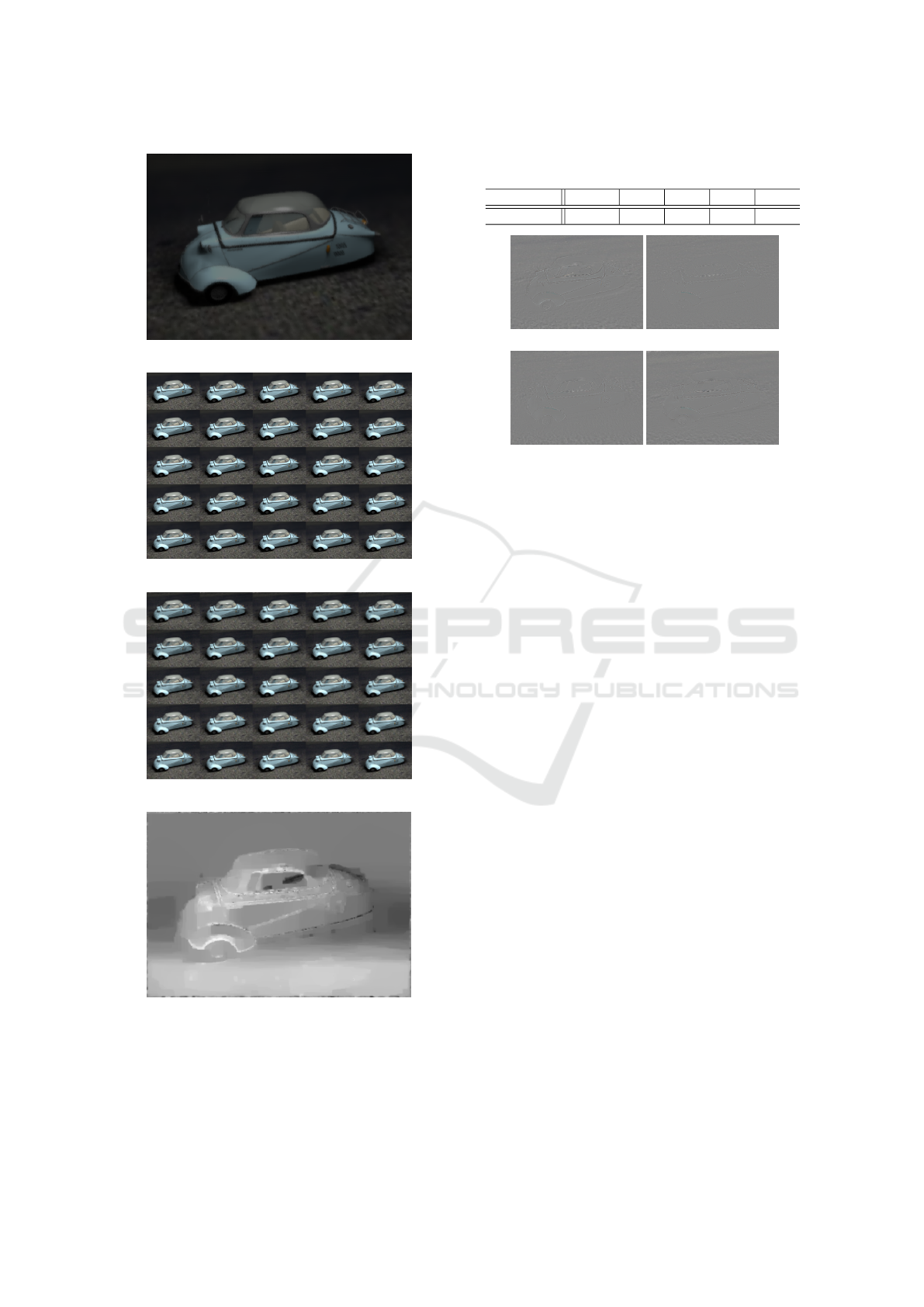
Figure 5: Input mixed-focus images.
Figure 6: Estimated Light field.
Figure 7: Ground truth of light field.
Figure 8: Input mixed-focus images.
5 CONCLUSION
In this paper, we propose a method for LF estima-
tion from mixed-focus images captured by a mixed-
Table 1: Reconstruction error (RMSE) of the restored sub-
aperture images.
Viewpoint (-2,-2) (0,0) (0,2) (2,0) Avg.
RMSE 6.10 5.86 5.51 5.90 5.73
(-2,-2) (0,0)
(0,2) (2,0)
Figure 9: The difference images between the estimated sub-
aperture images and the ground truth.
focus camera that performs pixel-by-pixel exposure
control while changing the focal distance. The pro-
posed method shows how to efficiently recover the
LF by separating the LF into an all-in-focus image,
a disparity image, and a non-diffuse reflection com-
ponent. Simulation experiments showed that the pro-
posed method is capable of recovering the LF appro-
priately. We plan to conduct demonstration experi-
ments using actual equipment in the future.
REFERENCES
Duarte, M. F., Davenport, M. A., Takhar, D., Laska, J. N.,
Sun, T., Kelly, K. F., and Baraniuk, R. G. (2008).
Single-pixel imaging via compressive sampling. IEEE
Signal Processing Magazine, 25(2):83–91.
Hashimoto, F., Ohba, H., Ote, K., Kakimoto, A., Tsukada,
H., and Ouchi, Y. (2021). 4d deep image prior:
dynamic pet image denoising using an unsupervised
four-dimensional branch convolutional neural net-
work. Physics in Medicine & Biology, 66(1):015006–.
Inagaki, Y., Kobayashi, Y., Takahashi, K., Fujii, T., and Na-
gahara, H. (2018). Learning to capture light fields
through a coded aperture camera. In Ferrari, V.,
Hebert, M., Sminchisescu, C., and Weiss, Y., edi-
tors, Computer Vision – ECCV 2018, pages 431–448,
Cham. Springer International Publishing.
Lin, X., Suo, J., Wetzstein, G., Dai, Q., and Raskar, R.
(2013). Coded focal stack photography. In IEEE In-
ternational Conference on Computational Photogra-
phy (ICCP), pages 1–9.
Luo, Y., Ren, J. S. J., Lin, M., Pang, J., Sun, W., Li, H., and
Lin, L. (2018). Single view stereo matching. CoRR,
abs/1803.02612.
VISAPP 2024 - 19th International Conference on Computer Vision Theory and Applications
790

Marwah, K., Wetzstein, G., Bando, Y., and Raskar, R.
(2013a). Compressive Light Field Photography us-
ing Overcomplete Dictionaries and Optimized Pro-
jections. ACM Trans. Graph. (Proc. SIGGRAPH),
32(4):1–11.
Marwah, K., Wetzstein, G., Bando, Y., and Raskar, R.
(2013b). Compressive Light Field Photography us-
ing Overcomplete Dictionaries and Optimized Pro-
jections. ACM Trans. Graph. (Proc. SIGGRAPH),
32(4):1–11.
Mildenhall, B., Srinivasan, P. P., Tancik, M., Barron, J. T.,
Ramamoorthi, R., and Ng, R. (2020). Nerf: Repre-
senting scenes as neural radiance fields for view syn-
thesis.
Ng, R. (2005). Light field photography with a hand-
held plenoptic camera. Stanford Tech. Report CTSR,
2005(2):1–11.
Ulyanov, D., Vedaldi, A., and Lempitsky, V. (2018). Deep
image prior. In Proceedings of the IEEE Conference
on Computer Vision and Pattern Recognition (CVPR),
pages 9446–9454.
Dense Light Field Imaging with Mixed Focus Camera
791
