
Self-Mounted Motion Capture System Using Mutual Projection of
Asynchronous Cameras
Kazusa Ozaki, Fumihiko Sakaue and Jun Sato
Nagoya Institute of Technology, Nagoya, Japan
Keywords:
Motion Capture Systems, Bundle Adjustment, Neural Network Representation, Asynchronous Stereo.
Abstract:
In this research, we propose a method for restoring three-dimensional motion from time-series images captured
by an asynchronous camera in order to realise a motion capture system using a camera attached to the body
surface. For this purpose, we represent the motion trajectory of each marker using a neural network, and
estimate the motion trajectory by optimising the neural network from the input images. It is also shown that
stable 3D restoration can be achieved using a method called mutual projection, assuming that the cameras are
reflecting each other. We show that it is possible to estimate 3D motion from asynchronous cameras with high
accuracy.
1 INTRODUCTION
In recent years, motion capture technology (Moes-
lund et al., 2006), which measures and analyses hu-
man movements into numerical values, has been used
in a wide range of fields. However, the current main-
stream motion capture method, the optical motion
capture method(Guerra-Filho, 2005), has high mea-
surement accuracy, but the system tends to be large
because it requires cameras to be set up around the
area to be captured.
Other than optical motion capture systems, there
are mechanical motion capture systems that use ac-
celeration sensors or angular acceleration sensors for
measurement(Roetenberg et al., 2009). Mechanical
systems use sensors for measurement and can capture
in various environments without the need to install
equipment such as cameras and markers, but have
lower accuracy than optical systems. In addition, the
sensors used for capturing are affected by magnetic
fields, making them unsuitable for locations with un-
stable magnetic fields.
In a previous study of motion capture in small-
scale systems, a method for acquiring motion infor-
mation by restoring the motion of a camera attached
to the human body using structure from motion tech-
nology has been proposed(Shiratori et al., 2011). This
method is relatively inaccurate compared to the actual
measurement method, as it does not directly capture
the markers, etc. There is also a method for captur-
ing motion by attaching an omni-directional camera
or other camera capable of capturing the target per-
son(Miura and Sako, 2020). Although this method
directly captures the object, there are many areas that
are hidden by occlusion, resulting in low measure-
ment accuracy.
As described above, methods for motion capture
without using an external camera have been proposed,
but each method has problems in terms of accuracy
and stability. In this study, we propose a method
to solve these problems by attaching a camera and a
marker to the object and using the camera as a marker
and a filming device. In this method, the camera at-
tached to the body is regarded as a marker, while other
markers and cameras are photographed and their 3D
positions are recovered for motion measurement. In
this case, a very strong geometric constraint called
mutual projection can be used, which enables stable
estimation and restoration of the camera position.
However, when using a stereo camera system such
as the one proposed in this system to perform restora-
tion, the cameras need to take pictures synchronously,
as the corresponding points taken at the same time are
required. However, as described above, the cameras
need to be connected to each other for synchronous
shooting, which makes it unsuitable for a method in
which the cameras are attached to the human body.
For this reason, this study presents a method that can
stably realise 3D restoration even from asynchronous
cameras. This method focuses on the motion trajec-
tory of each marker and restores parameters related to
the trajectory, enabling stable stereo restoration even
Ozaki, K., Sakaue, F. and Sato, J.
Self-Mounted Motion Capture System Using Mutual Projection of Asynchronous Cameras.
DOI: 10.5220/0012473500003660
Paper published under CC license (CC BY-NC-ND 4.0)
In Proceedings of the 19th International Joint Conference on Computer Vision, Imaging and Computer Graphics Theory and Applications (VISIGRAPP 2024) - Volume 4: VISAPP, pages
147-153
ISBN: 978-989-758-679-8; ISSN: 2184-4321
Proceedings Copyright © 2024 by SCITEPRESS – Science and Technology Publications, Lda.
147

from images captured by an asynchronous camera. In
this way, a method for stable motion restoration from
images taken by a group of cameras attached to the
human body is presented.
2 EPIPOLAR GEOMETRY AND
STEREO RECONSTRUCTION
In this section, we will explain the camera model used
in this research and a method for restoring 3D shapes
based on image information obtained from the camera
based on epipolar geometry.
2.1 Epipolar Geometry
First, 3D restoration using the stereo camera system
used in this study is described. In this study, the
3D information is recovered from the image infor-
mation obtained from the cameras. For this purpose,
the epipolar geometry(Hartley and Zisserman, 2003)
is used, which can represent multiple cameras. Let us
consider the case where two cameras capture a point
X =[X Y Z]
>
in 3D space and the points m =[u v]
>
and m
0
=[u
0
v
0
]
>
on the image are obtained. The fol-
lowing relation holds between these two points using
the fundamental matrix F that represents the relative
relationship between cameras.
e
m
0>
F
e
m = 0 (1)
where
e
m
0
,
e
m is the homogeneous representation of
m
0
, m and
˜
m = [m
T
1]
T
. Also, F is the fundamental
matrix, which represents the relative relationship be-
tween the two cameras. Images taken by two cameras,
the corresponding points will always satisfy this equa-
tion. In addition, F contains information about the
position and orientation between the cameras. There-
fore, this epipolar geometry can be used to determine
the relative attitude information between the cameras.
2.2 3D Reconstruction by Stereo
Camera System
Next, the camera projection matrix P is obtained from
the F matrix, and the 3D reconstruction is performed
using this matrix. The following relationship is es-
tablished between the camera matrix P and the points
X =[X Y Z]
>
in 3D space and m =[u v]
>
on the im-
age.
λ
u
v
1
=
p
11
p
12
p
13
p
14
p
21
p
22
p
23
p
24
p
31
p
32
p
33
p
34
X
Y
Z
1
(2)
where p
11
∼ p
34
are components of the camera pro-
jection matrix. where p
11
to p
34
are the elements of
the camera matrix. Eliminating λ from the equation
(2) and summarising for [X Y Z]
>
, we obtain the fol-
lowing.
p
31
u − p
11
p
32
u − p
12
p
33
u − p
13
p
31
v − p
21
p
32
v − p
22
p
33
v − p
23
X
Y
Z
=
p
14
− p
34
u
p
24
− p
34
v
(3)
This equation shows that two constraint equations for
X can be obtained from one camera if the camera ma-
trix and the point m on the image are known. Thus,
a 3D point X can be recovered if the corresponding
points taken by two or more cameras are available.
2.3 Bundle Adjustment
In 3D shape reconstruction with actual camera im-
ages, it is often not possible to find a suitable solution
due to various noise effects. This is because not only
the image points used for reconstruction, but also the
parameters in the camera matrix are strongly influ-
enced by noise. Therefore, in many cases, a method
called bundle adjustment is used to optimise the cam-
era parameters and the 3D restoration result to obtain
a more accurate estimation of the restoration result.
Bundle adjustment(Triggs et al., 2000) is a method
for optimising multiple parameters in a batch in order
to improve the estimation accuracy. This optimisation
is achieved by estimating the camera matrix P and the
three-dimensional point X in such a way that the error
in the reprojection of the estimated 3D shape onto the
image plane, i.e. the reprojection error, is minimised,
as described above in the following formula.
E =
1
2
∑
i
∑
j
{(u
j
i
− ¯u(P
j
, X
i
))
2
+ (v
j
i
− ¯v(P
j
, X
i
))
2
} (4)
where u
j
i
, v
j
i
are the coordinates of the observa-
tion point obtained by imaging the three-dimensional
point X
i
with camera j, ¯u(P
j
, X
i
) , ¯v(P
j
, X
i
) are the
coordinates of the three-dimensional point X
i
pro-
jected onto the image plane with coordinates obtained
by projecting the 3D point X
i
onto the image plane
by the camera P
j
. As this reprojection error is a non-
linear function, some reasonable initial values are re-
quired for its minimisation. For this reason, in general
3D reconstruction methods, an initial estimate of P is
made from the F matrix obtained based on epipolar
geometry, and bundle adjustment is carried out using
this as the initial value.
VISAPP 2024 - 19th International Conference on Computer Vision Theory and Applications
148
3 MUTUAL CAMERA
PROJECTION IN EPIPOLAR
GEOMETRY
This section describes a stereo reconstruction method
using mutual projection.
3.1 Mutual Camera Projection
By using the bundle adjustment presented in the pre-
vious section, the position and orientation of the cam-
era and the 3D shape can be estimated simultaneously.
However, in this research, both the camera and the
marker are mounted on the human body for measure-
ment, so the camera position varies significantly com-
pared to normal scenes. Therefore, an important issue
in this research is to stabilise the camera position. In
order to solve this problem, we utilise the mutual pro-
jection system (ITO and SATO, 2002).
The self-attached motion capture system proposed
in this study requires a camera mounted on the body
surface to capture other markers. Therefore, wide-
angle cameras that can capture a very large area are
used. As described above, not only the markers whose
positions are to be measured, but also the camera for
taking the images will be incorporated in the images
taken by each camera. Considering that the epipole
in the epipolar geometry coincides with the point at
which the optical centre of the camera is captured, it
can be seen that in this situation the epipole can be
directly obtained from the observed image. Since the
epipoles contain the position information of the cam-
eras, the relative positions of the cameras can be de-
termined very stably by obtaining them directly.
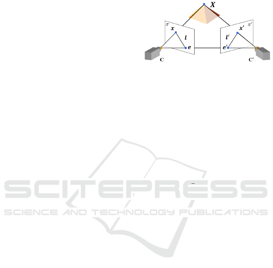
When two cameras are projected onto each other’s
image plane as epipoles e,e
0
as in Fig.1, the following
relationship is established between the basis matrix F
and the epipoles e,e
0
e and e
0
.
F
e
e = 0 (5)
F
>
e
e
0
= 0 (6)
where
e
e,
e
e
0
are homogeneous representations of e,e
0
.
Since this epipole places a strong constraint on the ba-
sis matrix F, the relative attitude information between
the two cameras can be obtained stably by calculating
F using the directly observed epipole.
3.2 Bundle Adjustment Using Mutual
Projection
The mutual projection in the estimation of the F ma-
trix described above allows a stable estimation of the
Figure 1: Epipolar geometry and epipole.Points e and e’ are
epipoles of cameras c and c’.
camera parameters. This is optimised by bundle ad-
justment to perform 3D reconstruction. In this case,
the strong constraints obtained by the mutual projec-
tion can also be used in the bundle adjustment. As
mentioned above, in mutual projection the camera po-
sition is captured directly. Therefore, when perform-
ing bundle adjustment, the reprojection error can be
calculated for the estimated camera position in addi-
tion to the reprojection error of the 3D points. Consid-
ering this, bundle adjustment using mutual projection
can be defined as minimising the reprojection error
of the reconstructed points as well as the reprojection
error of the epipoles by the following equation.
E
0
(P, X) = E +
1
2
∑
j
∑
k6= j
(e
j
−
¯
e(P
k
, T
j
))
2
(7)
where e is the epipole observed by the camera and
¯
e(P, T) are the coordinates of the estimated 3D posi-
tion of the camera T projected onto the image plane.
The reprojection error calculated in this way can
directly optimise the information on the camera po-
sition. Therefore, the estimation of the camera posi-
tion is more accurate than when estimating the camera
position only from the relation of the corresponding
points.
4 STEREO RECONSTRUCTION
USING ASYNCHRONOUS
CAMERAS
This section describes a method for stereo reconstruc-
tion using asynchronous cameras.
4.1 3D Trajectory Reconstruction Based
on Parameter Representation of 3D
Trajectories
At last, 3D reconstruction using asynchronous cam-
eras is described. All the methods described above
assume that multiple cameras are capturing the same
Self-Mounted Motion Capture System Using Mutual Projection of Asynchronous Cameras
149
scene, i.e. that they are acquiring information at
the same time. However, multiple cameras running
independently often capture images asynchronously.
Therefore, such an assumption is no longer valid
when synchronous camera systems are not used. This
makes proper 3D reconstruction difficult when us-
ing the epipolar geometry that is common in asyn-
chronous cameras.
In order to solve this problem, a method has
been proposed to transform the trajectory of the cor-
responding points into frequency space and restore
them as points in frequency space(Kakumu et al.,
2013). This method focuses on the trajectory as a
whole, rather than on each 3D point, and estimates
the frequency components that represent the trajec-
tory. This enables 3D reconstruction with an asyn-
chronous camera. However, in this method, the recon-
struction is carried out using an affine camera model
so that the 2D projected points and the 3D points can
be represented in a linear relationship. This makes it
difficult to apply when the cameras are located very
close to each other, as is the case in this study.
Here, viewing the frequency components recov-
ered by this method as parameters for parametrically
constructing the 3D trajectory, the reconstruction of
the 3D trajectory can be considered as the estima-
tion of parameters for constructing the trajectory. In
this case, as long as the necessary constraints for es-
timating the parameters are obtained, 3D reconstruc-
tion can be achieved appropriately even when images
taken at the same time are not available. In this study,
3D reconstruction from an asynchronous camera is
performed using such a parameter representation of
the trajectory.
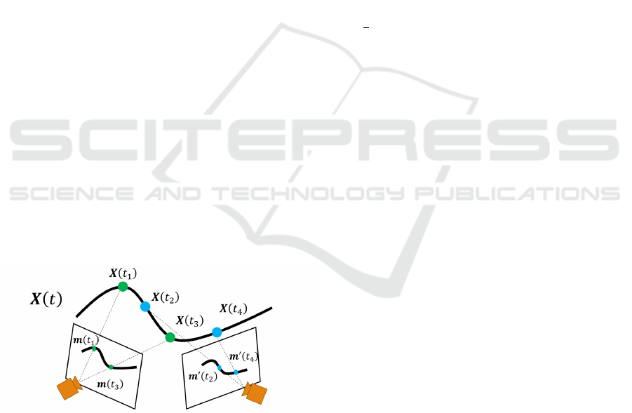
Figure 2: Example of the 3D trajectory and projected 3D
points.X is a 3D point, x is a projection point, and t is time.
4.2 Representation of 3D Trajectories
Using Neural Networks
A typical representation of the parametric representa-
tion of a 3D trajectory is the interpolation method us-
ing spline interpolation, etc. In the method, a 3D tra-
jectory can be constructed from multiple basis points.
Therefore, the estimation of the 3D trajectory in this
method is equivalent to the estimation of the basis
points. However, when using such an interpolation
method, the 3D trajectory that can be represented by
the chosen interpolation method is limited. In addi-
tion, if the corresponding points cannot be observed
due to occlusion or other reasons, appropriate estima-
tion will not be possible.
Therefore, this study adopts the representation of
trajectories using neural networks. This method fo-
cuses on the fact that neural networks are general-
purpose functions that can represent various func-
tions, and uses this functional representation to repre-
sent trajectories. In other words, when a certain time
t is input, the neural network is trained as a function
that outputs a 3D point at that time. This learning is
achieved by minimising the reprojection error at each
camera and each time, defined as follows.
E
00
=
1
2
∑
t
∑
i
∑
j
[{(u
j,t
i
− ¯u(P
t
j
, X
t
i
))
2
+ (v
j,t
i
− ¯v(P
t
j
, X
t
i
))
2
}
+
∑
k6= j
{(e
t
j
−
¯
e(P
t
k
, T
t
j
))
2
}]
(8)
where X
t
i
is the 3D point obtained when time t is in-
put to the neural network. Also, ¯u and ¯v are the pro-
jected points obtained by projecting the 3D point by
the camera matrix. By minimizing the loss function,
we can obtain a neural network that represents the
3D trajectory of the observed points taken by asyn-
chronous cameras.
Note that when using a neural network to repre-
sent an arbitrary function, it is known that if variables
such as time are input directly, it becomes difficult to
represent high-frequency components. To avoid this,
it is necessary to map these variables to a higher-order
space in advance using positional encoding. This
method is also used in this study, and t is input to the
neural network after being mapped to a higher-order
space. In addition, appropriate initial values are re-
quired for this non-linear minimisation. For this rea-
son, in this study, 2D points are interpolated in ad-
vance to create a set of pseudo-synchronised corre-
sponding points. The interpolated values are used for
synchronous bundle adjustment. The results obtained
are optimised using the method described above to es-
timate the final reconstruction result.
Furthermore, the parameter representation using
such a neural network is applicable not only to the 3D
points to be restored, but also to all parameters includ-
ing the camera position. Therefore, in this research,
the same representation is used for these parameters,
and the camera position and 3D trajectory are esti-
mated by minimising the reprojection error shown by
VISAPP 2024 - 19th International Conference on Computer Vision Theory and Applications
150
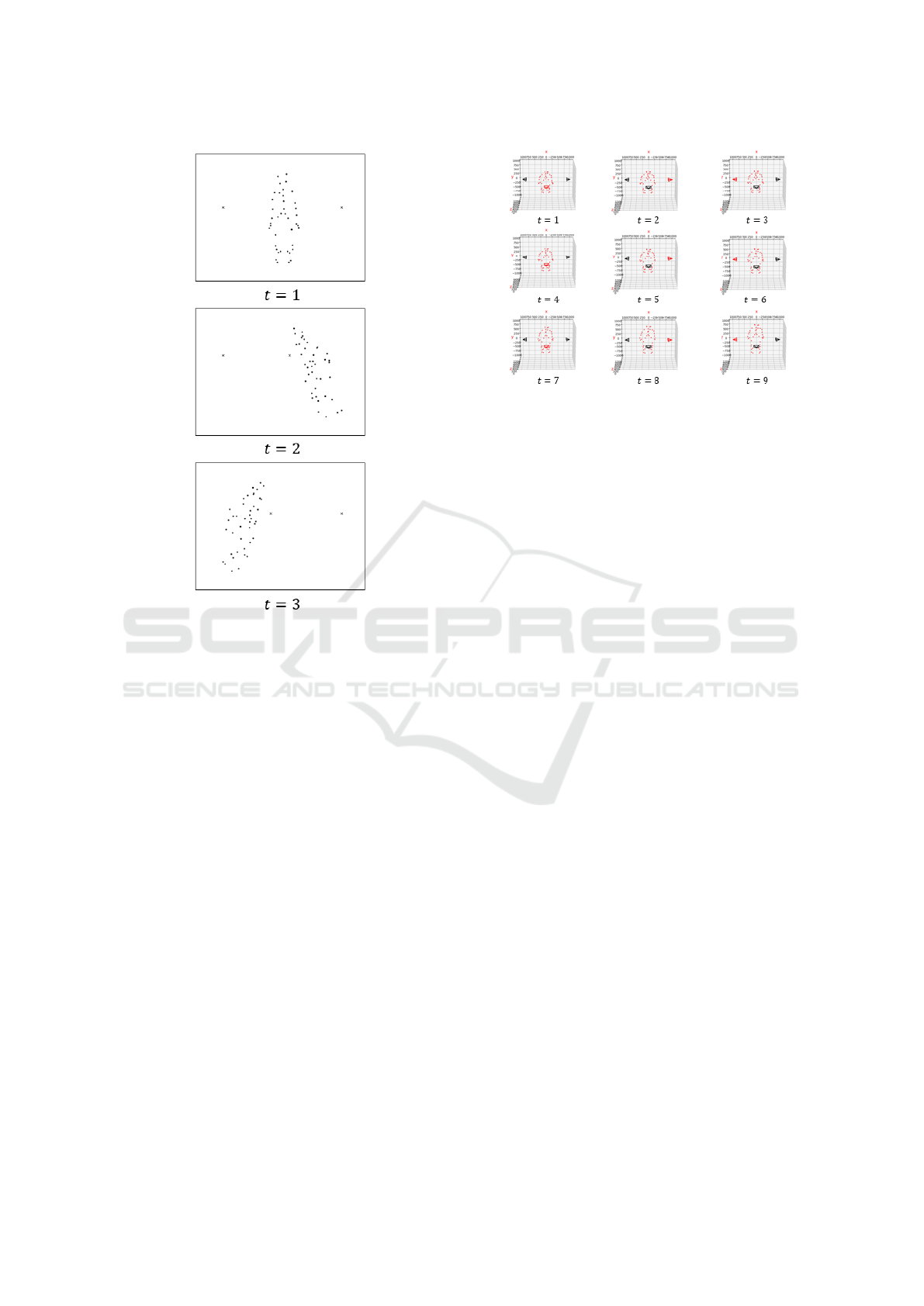
Figure 3: Examples of input images.The cross mark is an
epipole.
the equation (8). This enables stable estimation of the
3D trajectory even from asynchronous cameras.
5 EXPERIMENTAL RESULTS
In this section, we present the results of simulation-
based restoration using the proposed method.
5.1 Environment
The results of 3D reconstruction from images cap-
tured by an asynchronous camera using the pro-
posed method are presented. In this experiment,
the motion of doing a standing long jump was se-
lected from the CMU Graphics Lab Moiton Capture
Database(Carnegie Mellon University, 2003), and the
image taken by the virtual camera was used. The
scenes were taken by three cameras at different po-
sitions at different times, as shown in Fig.4. The red
dots in the figure represent the 3D point cloud and the
surrounding rectangles represent the cameras. In or-
der to reproduce the asynchronous situation where the
cameras were not synchronised, the 3D point cloud
was taken at a time when each camera was off by
Figure 4: Target 3D points.The red dots in the figure rep-
resent the 3D point cloud and the surrounding rectangles
represent the cameras.The red camera is the camera that is
projecting at that time.
three frames. The camera indicated in red in Fig.4
is the camera that is projecting at that time.
The images used for the actual reconstruction are
shown in Fig3. The images show the first image
taken by each camera. The black dots are the pro-
jected points of the 3D point cloud and the X marks
the epipoles of the cameras. From these images, the
3D reconstruction was carried out using the proposed
method. For comparison, the following methods were
used for the interpolation of asynchronous cameras,
with and without mutual projection restoration was
performed using neural networks, linear interpolation
and cubic spline interpolation, respectively.
We experimented with a NN structure consisting
of only one fully connected layer with 256 units, with
the input being 4-dimensional by positional encoding
and the 3-dimensional point X being the output. In
addition, the results of the neural network are opti-
mized using the equation (8) after initial learning of
the network using the spline results.
5.2 Results
The results of the restoration using each method are
shown in Fig.5. In all of these results, the restoration
is carried out using mutual projection. In the result
images, the true values are shown in red and the re-
covered results in blue. In addition, Table 1 shows
the restoration error (RMSE) with and without mu-
tual projection and when the restoration is carried out
using each interpolation method. These results show
that the 3D points reconstructed using the neural net-
work are more accurate than those reconstructed us-
ing linear interpolation or spline interpolation. It can
also be seen that the results of reconstruction using
mutual projection are more accurate for all interpola-
Self-Mounted Motion Capture System Using Mutual Projection of Asynchronous Cameras
151
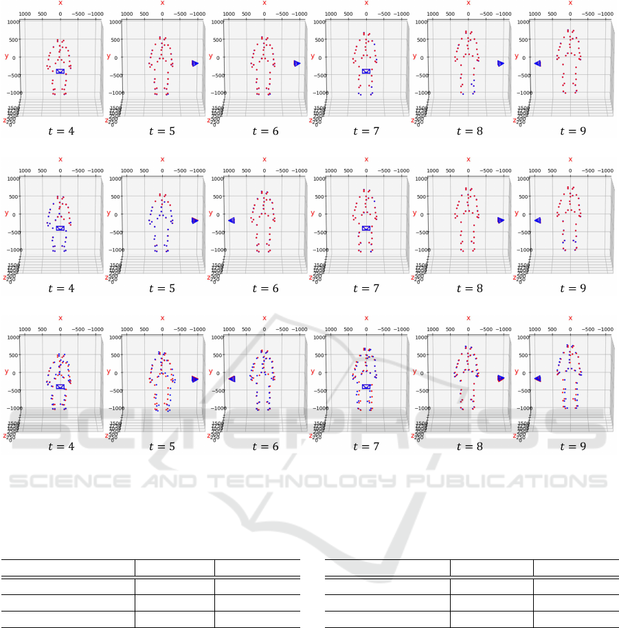
(a) NN
(b) Spline interpolation
(c) Linear Interpolation
Figure 5: Examples of 3D recunstruction.In all of these results, the restoration is carried out using mutual projection. The true
values are shown in red and the recovered results in blue.
Table 1: Reconstruction errors (RMSE) by each method
(mm).
w/ epipoles w/o epipoles
Linear interpolation 22.661 24.366
Cubic spline polation 6.881 6.970
NN 5.572 5.722
tion methods. These results confirm that the use of
mutual projection enables high-precision 3D restora-
tion even with an asynchronous camera.
The results of calculating the average restoration
error from 10 movements in the dataset are shown
in Table 2. These results confirm that the proposed
method can achieve highly accurate restoration.
6 CONCLUSION
In this study, a self-attached motion capture system
using mutual projection in an asynchronous camera
Table 2: Reconstruction errors (RMSE) by each method
from 10 movoments (mm).
w/ epipoles w/o epipoles
Linear interpolation 19.921 21.057
Spline interpolation 4.649 4.940
NN 4.313 4.596
is proposed as a method to realise small-scale mo-
tion capture without location constraints. To this
end, a method for stable 3D restoration even with
asynchronous cameras using mutual projection is pre-
sented.
REFERENCES
Carnegie Mellon University (2003). CMU Graphics Lab
Motion Capture Database. http://mocap.cs.cmu.edu/.
Guerra-Filho, G. (2005). Optical motion capture: Theory
and implementation. RITA, 12(2):61–90.
VISAPP 2024 - 19th International Conference on Computer Vision Theory and Applications
152

Hartley, R. and Zisserman, A. (2003). Multiple view geom-
etry in computer vision. Cambridge university press.
ITO, M. and SATO, J. (2002). Robust computation of
epipolar geometry from mutual projection of cam-
eras. IEICE transactions on information and systems,
85(3):600.
Kakumu, Y., Sakaue, F., Sato, J., Ishimaru, K., and Iman-
ishi, M. (2013). High frequency 3d reconstruction
from unsynchronized multiple cameras. In BMVC.
Miura, T. and Sako, S. (2020). 3d human pose estimation
model using location-maps for distorted and discon-
nected images by a wearable omnidirectional camera.
IPSJ Transactions on Computer Vision and Applica-
tions, 12:1–17.
Moeslund, T. B., Hilton, A., and Kr
¨
uger, V. (2006). A sur-
vey of advances in vision-based human motion cap-
ture and analysis. Computer vision and image under-
standing, 104(2-3):90–126.
Roetenberg, D., Luinge, H., Slycke, P., et al. (2009). Xsens
mvn: Full 6dof human motion tracking using minia-
ture inertial sensors. Xsens Motion Technologies BV,
Tech. Rep, 1:1–7.
Shiratori, T., Park, H. S., Sigal, L., Sheikh, Y., and Hodgins,
J. K. (2011). Motion capture from body-mounted
cameras. In ACM SIGGRAPH 2011 papers, pages 1–
10.
Triggs, B., McLauchlan, P. F., Hartley, R. I., and Fitzgibbon,
A. W. (2000). Bundle adjustment - a modern synthe-
sis. In Proceedings of the International Workshop on
Vision Algorithms: Theory and Practice, ICCV ’99,
pages 298–372, London, UK, UK. Springer-Verlag.
Self-Mounted Motion Capture System Using Mutual Projection of Asynchronous Cameras
153
