
Analysis of Scattering Media by High-Frequency Polarized Light
Projection Using Polarizing Projector
Aigo Ohno, Fumihiko Sakaue and Jun Sato
Nagoya Institute of Technology, Nagoya, Japan
Keywords:
Scattering Medium, Polarized Light, First-Order Scattering, Multiple Scattering, Specular Reflection, Diffuse
Reflection.
Abstract:
This paper proposes a special projection method called high-frequency polarized light projection using a po-
larizing projector to analyze scenes filled with scattering medium, and proposes a method to separate reflected
lights and scattered lights by scattering medium in the observed image. In high-frequency polarized light
projection, a high-frequency pattern is created by light with different polarization directions, projected onto
a scattering medium, and the reflected light is observed. The light scattered by the medium and the reflected
light from the object have different polarization properties, and we show that these two types of light can be
easily separated.
1 INTRODUCTION
In recent years, due to the development of IoT and
image information processing technologies, camera-
based information analysis has been used in various
scenes. In many cases, such technologies are based
on the assumption that the scene is a clear scene in
which light can travel straight ahead, such as in the
air. However, when targeting outdoor scenes such
as in-vehicle video analysis, scenes are often filled
with medium called scattering medium such as fog or
smoke. In such scenes, light emitted from objects is
scattered before it reaches the camera. This results in
an unclear observed image, making it difficult to use
techniques that assume a clear image. Therefore, a
method that can separate the effect of light scattering
by the scattering medium from the observed image
and obtain a clear image is required.
As a technique for this purpose, Nayar et al.(Nayar
et al., 2006) propose the separation of scattered light
using high-frequency projection. In this method, a
controllable light source such as a projector is used
to project and observe high-frequency patterns such
as fine checker patterns on the object. This method
enables the acquisition of images in which the ef-
fects of the scattering medium are suppressed and
separated with only a simple calculation. However,
this method requires multiple projection of images
with large changes in brightness and darkness, mak-
ing it difficult to use in driver assistance and other
applications that require human observation with the
naked eye. Mukaigawa et al.(Takatani et al., 2018)
have proposed a method for finely separating primary
scattered light, compound scattered light, specular re-
flected light, and diffuse reflected light by an object
using a method called multiple weighted measure-
ment. Although this method enables more detailed
analysis than previous methods, it is time-consuming
because it requires taking a variety of images under
different conditions.
On the other hand, research has also been con-
ducted to remove the effects of scattering from the
image information alone. Kaiming et al.e(He et al.,
2010) define a dark channel as the degree of white-
ness, and use it to locally correct the captured image,
thereby achieving processing that is unaffected by the
shading of fog. However, such models approximate
the scattering of light to some extent using a simple
model, and therefore, when the density of the scat-
tering medium is high, they are not able to perform
proper separation. In recent years, there have been
studies of using deep learning to remove the effects
of scattering from image information alone(Cai et al.,
2016; Ren et al., 2016; Gupta et al., 2015; Li et al.,
2017; Zhang and Patel, 2018; Yang and Sun, 2018;
Tang et al., 2014). These methods have been shown to
be able to separate fog with very high accuracy com-
pared to the physics-based methods described above.
However, the estimation results of these methods are
highly dependent on training data, making it difficult
772
Ohno, A., Sakaue, F. and Sato, J.
Analysis of Scattering Media by High-Frequency Polarized Light Projection Using Polarizing Projector.
DOI: 10.5220/0012473100003660
Paper published under CC license (CC BY-NC-ND 4.0)
In Proceedings of the 19th International Joint Conference on Computer Vision, Imaging and Computer Graphics Theory and Applications (VISIGRAPP 2024) - Volume 3: VISAPP, pages
772-778
ISBN: 978-989-758-679-8; ISSN: 2184-4321
Proceedings Copyright © 2024 by SCITEPRESS – Science and Technology Publications, Lda.

to guarantee their performance for unknown scenes.
This makes it difficult to use these methods in situ-
ations where high reliability is required, such as in
driver assistance.
Therefore, this paper proposes a method of sepa-
rating scattered light and reflected light from an ob-
ject using a projection method called high-frequency
polarized light projection. For this purpose, we show
how to construct a polarized light projector to realize
such described above high-frequency polarized light
projection. Since the method proposed in this study
is based on a physical model, it can be used indepen-
dently of the scene conditions. It can be easily applied
to various scenes because it can be estimated from a
small number of images. High-frequency polarized
light projection changes only the polarization state
of the projected image, so there is almost no flicker
when observed by the naked eye. This makes it pos-
sible to obtain an image that suppresses the effects of
scattering without changing the results of human ob-
servation, even in situations such as in-vehicle image
processing, where processing is performed simultane-
ously with human observation by the naked eye.
2 SCATTERED MEDIUM AND
LIGHT SCATTERING
At first, we will discuss the scattering of light and
its classification. Light travels in a straight line in a
material-free vacuum. However, in a real environ-
ment, light is reflected and attenuated in various di-
rections due to collisions with various particles, such
as oxygen and nitrogen molecules in the air, small
water particles, dust, and dirt. This phenomenon is
called light scattering, and it has a greater impact on
the visibility of objects in medium with a large num-
ber of particles, such as fog, smoke, and water. Such
a medium in which a large number of particles exist
is called a scattering medium.
Scattering medium are classified according to the
size of their constituent particles. Based on the ra-
tio of particle size to wavelength, they can be classi-
fied into Rayleigh scattering, Mie scattering, and ge-
ometric scattering. Since the projector used in this
study emits visible light and the scattering medium
is fog with a particle size of 1∼2µm, the scattering
phenomenon occurring in the scene is assumed to be
described by Mie scattering.
Also, scattering medium are classified according
to their optical thickness. Optical thickness is a mea-
sure of the opacity of a scattering medium, and the
greater the optical thickness, the opaquer the scatter-
ing medium. For light incident on an optically thin
scattering medium, the probability that the light will
incident on a particle in the medium and be reflected
in another direction is low, and is approximated by
a scattering model in which the number of scattering
events is limited to a single event. Such scattering is
called first-order scattering or single scattering.
When multiple reflections occur in a medium, it is
called complex scattering. Such scattering can be di-
vided into cases that can be described above by scat-
tering as few as 2∼4 times, and cases in which a
sufficiently large number of reflections occur, called
higher-order scattering. Low-order scattering is ob-
served as light with some directionality because the
number of times it is scattered in the medium is
smaller than that of first-order scattering, although
the number is larger. High-order scattering, on the
other hand, is caused by collisions with many parti-
cles in the medium, resulting in countless scatterings.
Higher-order scattering is represented as light spread-
ing in all directions with no directionality, since it
loses its directionality due to repeated reflections. In
this study, we use these scattering characteristics to
separate the light reflected from an object from the
light scattered by the scattering medium.
3 POLARIZATION PROPERTIES
3.1 Polarization
Next, we will discuss the characteristics of polarized
light used in this research. Although light is a trans-
verse wave that oscillates in various directions, polar-
ized light is light whose direction of oscillation is po-
larized in a specific direction. When polarized light is
observed through a polarizer, the observed intensity
changes as the polarizer is rotated. This intensity is
explained as described above using the polarizer ro-
tation angle φ, the maximum intensity of polarized
light I
max
, the minimum intensity I
min
, and the angle
φ
0
(polarization direction) of the polarizer that gives
the maximum intensity.
I(φ) =
I
max
+ I
min
2
+
I
max
− I
min
2
cos(2φ − 2φ
0
) (1)
This allows the intensity change of polarized light to
be expressed as the addition of natural light I
min
and
polarized light with an intensity of (I
max
− I
min
) as
shown in Fig 1
This polarization intensity is known to change
with reflection and scattering.
Analysis of Scattering Media by High-Frequency Polarized Light Projection Using Polarizing Projector
773
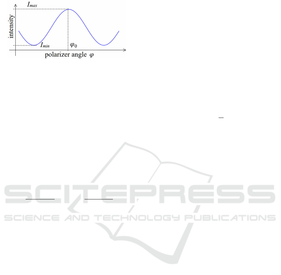
Figure 1: Intensity change of partially linearly polarized
light.
3.2 Polarization in Reflection
Next, consider the polarization of light reflected from
an object. Reflection of light is broadly classified into
specular reflection and diffuse reflection. At first, we
will discuss the change of polarization state in spec-
ular reflection. Specular reflection is represented as
a one-time reflection, and the change in polarization
state is expressed by Fresnel’s equation. In this case,
the direction of polarization and the intensity of the
light change, but the polarization is preserved. As
described above, the intensity reflectance R
p
parallel
to the plane of incidence and the intensity reflectance
R
s
perpendicular to the plane of incidence can be de-
scribed as follows:
R
p
=
tan(θ
t
− θ
i
)
tan(θ
t
− θ
i
)
!
2
, R
s
=
sin(θ
t
− θ
i
)
sin(θ
t
+ θ
i
)
!
2
(2)
where, θ
i
and θ
t
represent the angle of incidence and
refraction, respectively, and the reflection angle is as-
sumed to be equal to the angle of incidence assuming
that the object plane is optically smooth. In addition,
R
p
and R
s
are always R
s
≥ R
p
regardless of the angle
of incidence. At a certain angle of incidence, R
p
= 0,
and this angle of incidence is called the Brewster an-
gle. As described above, in specular reflection, the
polarization angle changes with the angle of incidence
of the ray.
Next, we consider the change in polarization in
diffuse reflection. In diffuse reflection, multiple re-
flections occur on the object surface or inside the
object, irradiating light uniformly in all directions.
In this case, even if the polarized light is incident,
its characteristics change in various directions as the
reflections are repeated. Therefore, the light ob-
served by diffuse reflection is a superposition of light
with various polarization directions, i.e., natural light.
Thus, when diffuse reflection occurs, the light ob-
served is natural light even when polarized light is
incident.
3.3 Polarization in Scattering
Next, we discuss the change in the polarization of
light due to scattering. When the medium is thin, scat-
tering in a scene can be represented by a first-order
scattering model in which light is scattered only once.
This is because, if we focus on a single ray of light,
the ray is considered to be reflected and refracted by
a single fog droplet in the scene and scattered. There-
fore, first-order scattering is considered to be similar
to specular reflection in fog droplets. Let n
i
and n
t
be the refractive indices of air and water, respectively,
and θ
i
be the angle of incidence to the fog drop. As
described above, the refraction angle θ
t
is expressed
by Snell’s law as follows:
θ
t
= arcsin
n
i
n
t
sinθ
i
(3)
Next, we consider the change in polarization state
in complex scattering. Polarized light enters an opti-
cally thick scattering medium, and the first-order scat-
tering described above is repeated multiple times. Al-
though each scattering can be described by the afore-
mentioned scattering model, the repetition of this pro-
cess results in reflections in various directions, i.e.,
a mixture of various polarizations. This means that
even if the incident light is polarized, the scattered
light is a superposition of various polarizations, just
like diffuse reflected light, so that the observed light
becomes closer to natural light as the number of
scatterings increases. Therefore, the light scattered
by lower-order scattering becomes partially polarized
light, while higher-order scattering becomes natural
light. In this paper, the composite scattered light is as-
sumed to be greatly affected by the higher-order scat-
tering and is treated as natural light.
4 SEPARATION OF SCATTERED
AND REFLECTED
COMPONENTS USING
POLARIZATION
4.1 Polarizing Projector
At first, we describe the polarizing projector used in
this study. In general projectors, the intensity of light
emitted from a light source is partially changed by us-
ing liquid crystals or micro-mirror arrays to project a
variety of images. Let us consider liquid crystal dis-
plays (LCDs), which are used in many projectors. A
typical LCD consists of a liquid crystal sandwiched
between two orthogonally oriented polarizing plates.
VISAPP 2024 - 19th International Conference on Computer Vision Theory and Applications
774

When no voltage is applied to the LCD, polarized
light incident from the back of the LCD is twisted
in various directions by the discretely arranged liquid
crystal molecules, resulting in a state close to unpo-
larized light. Therefore, a portion of the incident light
changes its direction of polarization to a state that al-
lows it to pass through the polarizer on the front sur-
face. On the other hand, when voltage is applied, the
orientation of the liquid crystal molecules is aligned,
and as a result, polarized light incident from the back
enters the front polarizer without changing its direc-
tion. Since the orientation of the two polarizers sand-
wiching the liquid crystal is orthogonal, light that has
passed through the liquid crystal cannot pass through
the polarizers. This makes it possible to control light
passing through the entire liquid crystal display. In
addition, by changing the voltage applied to the liquid
crystal, the alignment of the liquid crystal changes,
making it possible to observe light of various intensi-
ties.
Let us consider the case where the polarizer in-
stalled on the front surface is removed. In this case,
polarized light passing through the liquid crystal is
projected directly to the front surface. In other words,
the set of light rays whose intensity is adjusted by
passing through the polarizer is projected as a set of
light rays with different polarization directions. This
makes it possible to project light of various polar-
izations with different directions in the same way as
when projecting light of different intensities using an
ordinary projector. Regardless of the state of the liq-
uid crystal, the amplitude of the polarization, i.e., the
brightness of the observed image, remains almost un-
changed. Therefore, when observed by the naked eye,
an image with almost the same brightness is observed
regardless of the state of polarization. This makes it
possible to change the light source status of a scene
without significantly disturbing human observation.
In this paper, we call such a projector a polarizing
projector and show how to use it to separate scattered
light from reflected light.
Note that polarizing projectors do not directly
control the direction of polarization, but rather con-
trol the degree of polarization of the light that passes
through them, i.e., how close to perfect polarization
or how close to natural light the light is. Therefore, it
is not possible to directly project perfectly polarized
light that is orthogonal to the polarizer mounted on the
back of the liquid crystal. However, considering that
partial polarization and natural light can be expressed
as a linear combination of orthogonal perfect polar-
izations, the partial polarization obtained through the
LCD can be expressed as a linear combination of a
perfect polarization with an orientation equal to that
of the polarizer on the back and an orthogonal per-
fect polarization. Considering the linearity of light,
multiple images taken with varying partial polariza-
tion can easily be linearly combined to produce an
image when irradiated with perfect polarization.
Furthermore, polarization can be adjusted for each
pixel in a polarizing projector. This allows for the
synthesis of various polarizing projections, such as
the synthesis of polarization stripe patterns.
By using this to project various polarization pat-
terns, scattered light in an observed image can be sep-
arated.
4.2 Separation of Reflected and
Scattered Light Based on
Polarization
At first, we consider the case where polarized light is
projected with the same orientation to the scene using
a polarizing projector, as shown in Fig 2.
Figure 2: Single polarized light projection.
As mentioned previously, the first-order scattered
light from the scattering medium and the mirror re-
flection light from the object retain the polarization
property. On the other hand, the compound scattered
light and the diffuse reflected light from the object
surface are natural light. Let us consider the case
where such light is observed by a polarization cam-
era. In this case, the observed light is partially po-
larized light that is a combination of natural light and
perfectly polarized light. Let us assume that the dif-
fuse reflected light and the composite scattered light
are perfect natural light. In this case, the natural light
indicated by the equation Eq.(1) is a combination of
diffuse reflection and complex scattered light. On the
other hand, perfectly polarized light is a composite of
first-order scattered light and specular reflected light.
Both of these two components contain both re-
flected and scattered light from the object. If all light
reflected from an object is diffuse reflected light or if
there is no compound scattered light, it is possible to
separate reflected and scattered light by this method.
Analysis of Scattering Media by High-Frequency Polarized Light Projection Using Polarizing Projector
775
However, in general scenes, such assumptions do not
hold, and it is difficult to separate them by simple po-
larization alone.
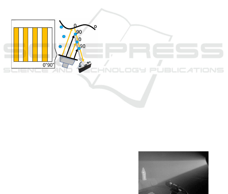
4.3 Separation of Specular Reflection
by High-Frequency Polarized Light
Projection
In this study, we propose a method for separating ob-
ject specular reflection light by high-frequency polar-
ized light projection using a polarizing projector. To
separate the first-order scattered light from fog and
the specular reflection light from the object surface,
this study takes advantage of the fact that fog has a
spatial thickness. In other words, we propose a light
separation method that takes advantage of the differ-
ence between fog, in which a first-order scattered light
is integrated in the depth direction of the camera, and
an object, in which specular reflection occurs only on
its surface.
Figure 3: High-frequency polarized light projection.
Let us now consider the case where a polarization
pattern is projected onto the scene such that the di-
rection of polarization changes horizontally to 0
◦
and
90
◦
at a high-frequency polarized light projection, as
shown in Fig 3. When the scene is observed by a po-
larization camera from a different direction from that
of the projector, as shown in Fig 3, there will be dif-
ferent polarizations on the observed light path. There-
fore, the scattered light observed by the camera is a
combination of the first-order scattered light with a
polarization of 0 degrees and the first-order scattered
light with a polarization of 90 degrees, i.e., natural
light. On the other hand, the light reflected from the
specular surface of an object is generated only on the
surface of the object, and thus is observed with perfect
polarization. This makes it possible to easily separate
the perfectly polarized light from the specularly re-
flected light, since the only perfectly polarized light
in the observed light is the specularly reflected light.
4.4 Separation of First-Order Scattered
Light
Finally, we describe a method for separating first-
order scattered light from fog. The diffuse reflection
component from objects and the combined scattered
light from the medium are components that change to
natural light in the scene. Therefore, they are con-
sidered to have the same intensity in both cases of
high-frequency polarized light projection and single-
directional polarized light projection. Therefore, by
subtracting the natural light image obtained by single
polarized light projection from the natural light im-
age obtained by high-frequency polarized light pro-
jection, the first-order scattered light from the fog can
be easily separated. This makes it possible to obtain
an image containing only scattered light from fog and
an image containing only reflected light from objects
with only two projection/photographing steps.
Note that it is difficult to completely separate the
complex scattered light by the medium and the diffuse
reflected light by this method alone because of their
close polarization characteristics. However, since the
complex scattered light are weaker than the first-order
scattering, their effect is small in scenes with low fog
density. Furthermore, by combination with the usual
high-frequency projection with varying brightness, it
is possible to separate these components as well.
5 EXPERIMENTAL RESULTS
5.1 Environment
The results of the separation of reflected light and
scattered light using the proposed method are pre-
sented. In this experiment, fog was generated in
a plastic greenhouse in which observation targets
were set up. High-frequency polarized light projec-
tion patterns and single polarized light projection pat-
terns were projected onto the scene, which was pho-
tographed by a polarization camera. Fig 4 shows the
scene.
Figure 4: Experimental environment.
Fig 5 shows an image taken under high-frequency
VISAPP 2024 - 19th International Conference on Computer Vision Theory and Applications
776
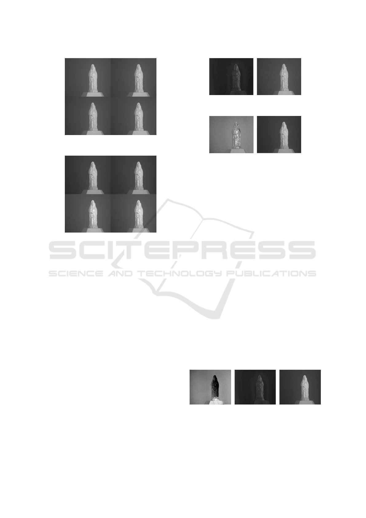
Figure 5: Images under high-frequency polarized light pro-
jection.
Figure 6: Images under single polarized light projection.
polarization, and Fig 6 shows an image taken under
single polarization, respectively. These four images
were taken simultaneously by the polarization cam-
era through filters with polarization angles of 0
◦
(up-
per left), 45
◦
(upper right), 90
◦
(lower left), and 135
◦
(lower right), respectively. The results of these two
types of images show that the brightness of the fog
only around the object in the images taken under sin-
gle polarization is different for each polarization an-
gle. This is thought to be due to the fact that the scat-
tered light from the fog is strongly partially polarized,
resulting in a large change in the intensity observed at
each angle. On the other hand, when high-frequency
polarized light projection is used, the fog is observed
to be almost equally bright in all polarized light im-
ages. This is considered to be a result of the fact that
the first-order scattered light from the fog is observed
as natural light due to the high-frequency polarization.
5.2 Results of Separation
Next, we show the results of separating the observed
light using the proposed method. At first, the results
of separating natural light and polarization compo-
nents for each captured image are shown in Fig 7 and
Fig 8. The results show that almost no polarized
light is observed outside of the object surface at the
base of the high-frequency polarized light projection.
Figure 7: Polarized light (left) and natural light (right) in
high-frequency polarized light projection.
Figure 8: Polarized light (left) and natural light (right) in
single polarized light projection.
This may be due to the fact that the high-frequency
polarized light projection allows the thicker parts of
the object to be observed as natural light. On the other
hand, in the case of single polarized light projection,
polarization is also observed in the fog area, indicat-
ing that first-order scattering from the fog is observed
as polarized light.
The results of the separation of the scattering
and reflection components based on these images are
shown in Fig 9. The results show that the brightness
of the fog first-order scattering image decreases in
the area where the object is placed. This is thought
to be due to a decrease in the fog thickness caused
by the placement of the object. In the specular re-
flection component, the brightness increases in areas
where the normal direction is the same, indicating that
it is observed as a specular reflection. In the com-
posite image of diffuse reflection and composite scat-
tering, diffuse reflection from the entire object sur-
face is observed. The brightness of the areas where
there are no objects is suppressed, confirming that
composite scattering was not strong in this environ-
ment. These results confirm that the combination of
single-frequency polarized light projection and high-
frequency polarized light projection can achieve sepa-
ration according to the characteristics of the observed
image with only two projection and imaging.
Figure 9: Results of separation of reflection and scattering
components: fog first-order scattering (left), specular reflec-
tion (center), diffuse reflection + complex scattering (right).
Analysis of Scattering Media by High-Frequency Polarized Light Projection Using Polarizing Projector
777

6 CONCLUSION
In this paper, we propose a method for separat-
ing various components in an observed image, such
as reflected and scattered components, by means of
high-frequency polarized light projection and high-
frequency projection using a polarizing projector. We
also show how to configure a polarizing projector to
realize this method. In the future, a method to com-
pletely separate the scattering and reflection compo-
nents by separating diffuse and composite scattering
will be investigated.
REFERENCES
Cai, B., Xu, X., Jia, K., Qing, C., and Tao, D. (2016).
Dehazenet: An end-to-end system for single image
haze removal. IEEE transactions on image process-
ing, 25(11):5187–5198.
Gupta, M., Nayar, S. K., Hullin, M. B., and Martin,
J. (2015). Phasor imaging: A generalization of
correlation-based time-of-flight imaging. ACM Trans-
actions on Graphics (ToG), 34(5):1–18.
He, K., Sun, J., and Tang, X. (2010). Single image haze
removal using dark channel prior. IEEE transac-
tions on pattern analysis and machine intelligence,
33(12):2341–2353.
Li, B., Peng, X., Wang, Z., Xu, J., and Feng, D. (2017).
Aod-net: All-in-one dehazing network. In Proceed-
ings of the IEEE international conference on com-
puter vision, pages 4770–4778.
Nayar, S. K., Krishnan, G., Grossberg, M. D., and Raskar,
R. (2006). Fast separation of direct and global com-
ponents of a scene using high frequency illumination.
In ACM SIGGRAPH 2006 Papers, pages 935–944.
Ren, W., Liu, S., Zhang, H., Pan, J., Cao, X., and Yang,
M.-H. (2016). Single image dehazing via multi-scale
convolutional neural networks. In Computer Vision–
ECCV 2016: 14th European Conference, Amsterdam,
The Netherlands, October 11-14, 2016, Proceedings,
Part II 14, pages 154–169. Springer.
Takatani, T., Mukaigawa, Y., Matsushita, Y., and Yagi, Y.
(2018). Decomposition of reflection and scattering by
multiple-weighted measurements. IPSJ Transactions
on Computer Vision and Applications, 10(1):1–13.
Tang, K., Yang, J., and Wang, J. (2014). Investigating haze-
relevant features in a learning framework for image
dehazing. In Proceedings of the IEEE conference on
computer vision and pattern recognition, pages 2995–
3000.
Yang, D. and Sun, J. (2018). Proximal dehaze-net: A prior
learning-based deep network for single image dehaz-
ing. In Proceedings of the european conference on
computer vision (ECCV), pages 702–717.
Zhang, H. and Patel, V. M. (2018). Densely connected pyra-
mid dehazing network. In Proceedings of the IEEE
conference on computer vision and pattern recogni-
tion, pages 3194–3203.
VISAPP 2024 - 19th International Conference on Computer Vision Theory and Applications
778
