
Fast and Reliable Inpainting for Real-Time
Immersive Video Rendering
Jakub Stankowski
a
and Adrian Dziembowski
b
Institute of Multimedia Telecommunications, Poznan University of Technology, Poznań, Poland
Keywords: Immersive Video, Inpainting, Virtual View Synthesis, Real-Time Video Processing.
Abstract: In this paper, the authors describe a fast view inpainting algorithm dedicated to practical, real-time immersive
video systems. Inpainting is an inherent step of the entire virtual view rendering process, allowing for
achieving high Quality of Experience (QoE) for a user of the immersive video system. The authors propose a
novel approach for inpainting, based on dividing the inpainting process into two independent, highly
parallelizable stages: view analysis and hole filling. In total, four methods of view analysis and two methods
of hole filling were developed, implemented, and evaluated, both in terms of computational time and quality
of the virtual view. The proposed technique was compared against an efficient state-of-the-art iterative
inpainting technique. The results show that the proposal allows for achieving good objective and subjective
quality, requiring less than 2 ms for inpainting of a frame of the typical FullHD multiview sequence.
1 INTRODUCTION
There is currently a growing interest in immersive
video and virtual reality systems, where users can
virtually immerse themselves in the scene (Vadakital,
2022), (Wien, 2019), (Boyce, 2021). These systems
have evolved from previous free-viewpoint television
and free navigation systems (Tanimoto, 2012),
allowing users to navigate around a scene
(Stankiewicz, 2018) (Fig. 1).
In immersive video systems, a scene is captured
by a set of precisely calibrated cameras (Tao, 2021).
The number of cameras used can vary, ranging from
less than ten (Mieloch2, 2020) to even hundreds
(Fujii, 2006). However, in order to provide smooth
virtual navigation, users should not be limited to
explicitly captured camera videos (blue cameras in
Fig. 1). They should have the ability to choose their
preferred viewport (orange camera in Fig. 1), which
needs to be rendered using data from the input
cameras (Fachada, 2018), (Dziembowski, 2019). This
rendering process requires creating a 3D model of the
scene and calculating the precise position of each
captured object. Usually, the 3D scene is represented
as MVD (Müller, 2011) (multiview video plus depth).
In the MVD representation, each input view is
a
https://orcid.org/0000-0002-5105-5090
b
https://orcid.org/0000-0001-7426-3362
accompanied by the corresponding depth map (either
captured by time-of-flight cameras (Xiang, 2013) or
estimated based on the input views (Mieloch, 2020)).
Figure 1: Idea of an immersive video system; blue: input
views, orange: virtual view.
In the MVD representation, the typical rendering
(also called the virtual view synthesis) process
comprises four main steps:
1. depth reprojection (creation of the depth map
corresponding to the virtual view),
2. texture reprojection (creation of the virtual view),
3. inpainting (filling of areas, which were not
reprojected from input views),
4. optional virtual view postprocessing (e.g.,
additional filtration (Dziembowski, 2016) or color
correction (Dziembowski, 2018)).
694
Stankowski, J. and Dziembowski, A.
Fast and Reliable Inpainting for Real-Time Immersive Video Rendering.
DOI: 10.5220/0012452000003660
Paper published under CC license (CC BY-NC-ND 4.0)
In Proceedings of the 19th International Joint Conference on Computer Vision, Imaging and Computer Graphics Theory and Applications (VISIGRAPP 2024) - Volume 3: VISAPP, pages
694-702
ISBN: 978-989-758-679-8; ISSN: 2184-4321
Proceedings Copyright © 2024 by SCITEPRESS – Science and Technology Publications, Lda.
In order to provide a high quality of experience for
the viewer, the entire rendering has to be performed
in real-time. Therefore, all the steps have to be as fast
as possible. In this paper, we focus on the efficient
method of inpainting, which can be used in the
practical immersive video system.
In general, image inpainting is a well-known and
widely described topic, initially developed for such
applications as image restoration or watermark
removal (Bertalmio, 2000), (Levin, 2003), (Criminisi,
2004), (Barnes, 2009). The general idea of inpainting
is the same independently on the application – filling
of selected parts of an image (“holes”, Fig. 2) using
information from its remaining area (e.g., the
neighborhood of the holes). Therefore, even the
simplest methods developed for other applications
can be used for inpainting the virtual views in the
immersive video system (Tezuka, 2015). Such an
approach, however, does not take advantage of
additional information available in the immersive
video system – the depth maps (Fig. 3).
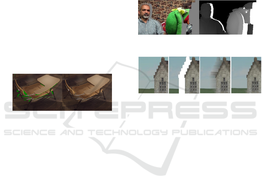
Figure 2: Idea of an image inpainting. Both images contain
a fragment of a synthesized virtual view. Left – a direct
result of a view reprojection. Right – virtual view inpainted
in order to conceal the presence of missing pixels.
The main reason, which introduces holes in the virtual
view are occlusions. When changing the watching
perspective, some parts of the scene – occluded in the
input views – should become visible in the virtual
view. These areas (called “disocclusions”) cannot be
synthesized since they are not available in any input
views. Disocclusions need to be inpainted using
information from the background (Fig. 4), not the
foreground objects (which occluded these parts of the
background in the input views) (Oh, 2009), (Zinger,
2010). There are numerous depth-based inpainting
methods described in the literature. These methods
may follow various principles, e.g., simple extensions
of typical inpainting methods (Daribo, 2010),
(Buyssens, 2017), (Cho, 2017), background warping
(Wang, 2011), (Khatiullin, 2018), usage of
optimization techniques (Mao, 2014), background
calculation (Yao, 2014), (Luo, 2017), or temporal
consistency preservation (Liu, 2012), (Lai, 2017).
There are numerous depth-based inpainting
methods described in the literature. These methods
may follow various principles, e.g., simple extensions
of typical inpainting methods (Daribo, 2010),
(Buyssens, 2017), (Cho, 2017), background warping
(Wang, 2011), (Khatiullin, 2018), usage of
optimization techniques (Mao, 2014), background
calculation (Yao, 2014), (Luo, 2017), or temporal
consistency preservation (Liu, 2012), (Lai, 2017). As
stated by the authors of all the abovementioned
papers, each of these methods can be used for
efficient inpainting of holes in the virtual view in
terms of perceived quality.
Figure 3: Virtual view and corresponding depth map.
A
B
C D
Figure 4: Basic vs. depth-based inpainting; A: reference
view, B: reprojected view, C and D: B with holes filled with
(D) and without (C) depth-based inpainting.
However, the practical, immersive video system
has an additional requirement, which has to be
fulfilled – the entire view rendering pipeline at the
user’s end has to be performed in real-time.
Therefore, a practical inpainting method must not
only provide decent quality but also be as fast as
possible. The proposed inpainting algorithm satisfies
both requirements, providing decent quality inpainted
regions while minimizing computational time.
2 REAL-TIME RENDERING
There are several real-time rendering methods, which
could be used in an immersive video system. Most of
them require dedicated hardware, such as powerful
graphic cards (Nonaka, 2018), FPGA devices (Li,
2019), or even VLSI devices (Huang, 2019), which
makes them less practical and versatile than CPU-
based techniques (Stankowski, 2023). The CPU-
based rendering can be successfully used even in low-
cost, practical immersive video systems where a user
accesses the immersive content via a simple personal
computer or even a laptop (Dziembowski2, 2018).
Fast and Reliable Inpainting for Real-Time Immersive Video Rendering
695

3 PROPOSAL
The proposed solution is a non-iterative inpainting
algorithm based on two ideas. The first one is to
perform inpainting based on the nearest valid pixel(s)
available in the same row or column as the processed
one. The second idea is to divide inpainting into two
separate (and parallelizable) stages: analysis and
processing.
Image analysis, the first stage of the proposed
algorithm, is designed to find missing pixels (holes)
that have to be inpainted and to determine the position
of valid pixels that can be used as a source during the
processing stage. In order to keep the computational
complexity reasonably low, up to four sources are
searched. As presented in Fig. 5, the first set of valid
pixels is determined by scanning within the same row
(nearest available pixels to the left and right), while
the second set is determined by scanning within the
same column (nearest available pixels above and
below). The position of found inpainting sources is
then stored in buffers for further processing.
Figure 5: Illustration showing the exemplary location of
valid pixels used as a source for inpainting a missing pixel
found within the same row/column.
The second stage of the proposed algorithm is the
actual filling of missing pixels. In this stage, valid
source coordinates stored in intermediate buffers are
used and the depth-based inpainting is performed. In
total, two approaches to depth-based inpainting were
proposed and investigated. The simpler one selects
the source with the farthest depth (considered as
related to the background) and will be referred to as
“selection inpainting” method. The more
sophisticated method finds the farthest depth and
finds all source pixels within the allowed depth range
around the farthest one. The found sources are then
adaptively merged by calculating a weighted average,
while the weight depends on the depth difference and
the distance between pixels. This approach will be
called “merging inpainting”.
When compared to the iterative approach
(Bertalmio, 2000), the non-iterative inpainting has
several advantages. The processing is done in a single
pass, which allows for achieving predictable
computing time. Additionally, the non-iterative
inpainting reduces memory bandwidth by avoiding
repetitive scanning of the entire image buffer.
Moreover, the separation into stages allows for the
division of the computation into several independent
tasks and consequently for effective parallelization.
4 IMPLEMENTATION
In order to evaluate the proposed algorithm, the
authors prepared several implementations. The
inpainting analysis was implemented in four different
manners: naïve, corners originating, rows-columns,
and tile-based.
The naïve analysis is the conceptually simplest
one. For every missing pixel, a full scan in each
direction is performed. The pixels within a row or a
column are browsed (starting from the closest one)
until a valid one is found (or an image edge is
encountered). The processing of each pixel is
independent of each other, and the search operation
can be easily divided into many threads.
The remaining approaches (corners originating,
rows-columns, and tile-based) do not require
exhaustive search but instead introduce data
dependency between neighboring pixels. One can
notice that in a consistent group of missing pixels
within a single row (see Fig 5), all of them will have
the same coordinates for left and right valid pixels.
Therefore, there is no need to repeatedly scan the
same area and the valid pixel coordinated from
neighboring missing pixels can be reused.
In corners originating implementation, the
analysis is performed in two passes. The left-top pass
detects left and above valid pixels, and the bottom-
right pass detects right and below valid pixels. This
approach has low computational and memory
complexity, but due to data dependency, the
possibility of parallelization is limited to two threads
(the first thread for the left-top pass and the second
thread for the bottom-right pass).
The rows-columns implementation defines four
separate passes dedicated for searching left, right,
above, and below valid pixels. This means that the
image has to be scanned four times but – on the other
hand – it is more prospective for parallelization. For
example, for left or right valid pixel search, the data
dependency occurs only within an image row. This
leads us to the conclusion that each row could be
analyzed separately. In the case of analyzing the
vertical direction, the dependency occurs only within
an image column – allowing for processing each
column independently.
The tile-based variant aims for the reduction of
required memory bandwidth and compute burden
VISAPP 2024 - 19th International Conference on Computer Vision Theory and Applications
696
while preserving the parallelization ability. This
approach introduces an additional pre-analysis pass
intended to detect areas of the image that contain
holes (missing pixels). These areas are grouped into
square tiles with a size equal to 64×64 (the optimal
size was determined experimentally), and tiles
containing any holes are marked as “inpainting
required”. Subsequently, tiles marked as required for
further processing are analyzed using the
abovementioned rows-columns method. This
approach allows for reducing the impact of multiple
analysis passes introduced by the original rows-
columns method. Inpainting processing
implementation is quite straightforward since there
are no data dependencies at this stage.
All listed analysis and processing methods were
implemented in two variants: single-threaded and
multithreaded. In the case of the parallel,
multithreaded variant, authors spent a lot of effort in
preparing a flexible implementation that scales up to
dozens of threads and exploits the possibilities of
modern multicore CPUs.
In order to perform a fair comparison to the state-
of-the-art iterative approach (Bertalmio, 2000),
authors prepared an efficient and simplified
implementation of this algorithm (both single and
multithreaded) and included it in the performance
evaluation.
5 EXPERIMENTS
5.1 Methodology
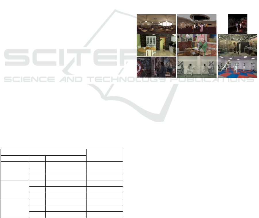
The experiments were performed on a test set
containing 9 miscellaneous test sequences,
commonly used in immersive video applications, e.g.,
within ISO/IEC JTC1/SC29/WG04 MPEG Video
Table 1: Test sequences.
Se
q
uence
Resolution
T
yp
e ID Name
ERP
A01 ClassroomVideo
1
4096×2048
C01 Hijac
k
2
4096×2048
C02 Cyberpun
k
3
2048×2048
Perspective
(CG)
J01 Kitchen
4
1920×1080
J04 Fan
5
1920×1080
W02 Dancin
g
4
1920×1080
Perspective
(natural)
D01 Painte
r
6
2048×1088
L01 Fencing
7
1920×1080
L03 MartialArts
8
1920×1080
1
(Kroon, 2018),
2
(Doré, 2018),
3
(Jeong, 2021),
4
(Boissonade,
2018),
5
(Doré, 2020),
6
(Doyen, 2018),
7
(Domański, 2016),
8
(Mieloch, 2023)
Coding group (ISO, 2023) (Table 1, Fig. 6). The
proposal was compared with a fast implementation of
the state-of-the-art iterative inpainting method
(referred as “I”) – the depth-based extension of
(Bertalmio, 2000). Both inpainting algorithms were
implemented within the real-time CPU-based virtual
view synthesizer, described by the authors of this
manuscript in (Stankowski, 2023).
The efficiency of the proposed view synthesizer
(including proposed inpainting) was compared with
the state-of-the-art view rendering technique –
ISO/IEC MPEG’s reference software, RVS (Fachada,
2018), (ISO, 2018). The computational time was
evaluated on a modern x86-64, 12-core CPU: AMD
Ryzen 9 5900X. The processing time was measured
using precision time stamps according to (Microsoft,
2020). The quality of rendered virtual views was
assessed using two commonly used full-reference
objective quality metrics: IV-PSNR (Dziembowski,
2022) and WS-PSNR (Sun, 2017).
Figure 6: Test sequences; first row (from left): A01, C01,
C02; second row: J01, J04, W02; third row: D01, L01, L03.
5.2 Computational Time Evaluation
The computational complexity of the proposed
algorithm was evaluated by performing virtual view
synthesis and measuring processing time. Table 2 and
Table 3 contain detailed analysis of each
implementation gathered for Painter (FullHD,
perspective) and ClassroomVideo (4K, ERP)
sequences. Separate processing times (Microsoft,
2020) are shown for each analysis and filling
algorithm. Moreover, the implementation of state-of-
the-art iterative inpainting was included as a
reference.
Two variants of synthesis conditions were
evaluated in order to evaluate algorithms in different
conditions:
1. with two source views – leading to a small number
of missing pixels in the virtual view,
2. with only one source view – leading to a vast
number of missing pixels.
Fast and Reliable Inpainting for Real-Time Immersive Video Rendering
697
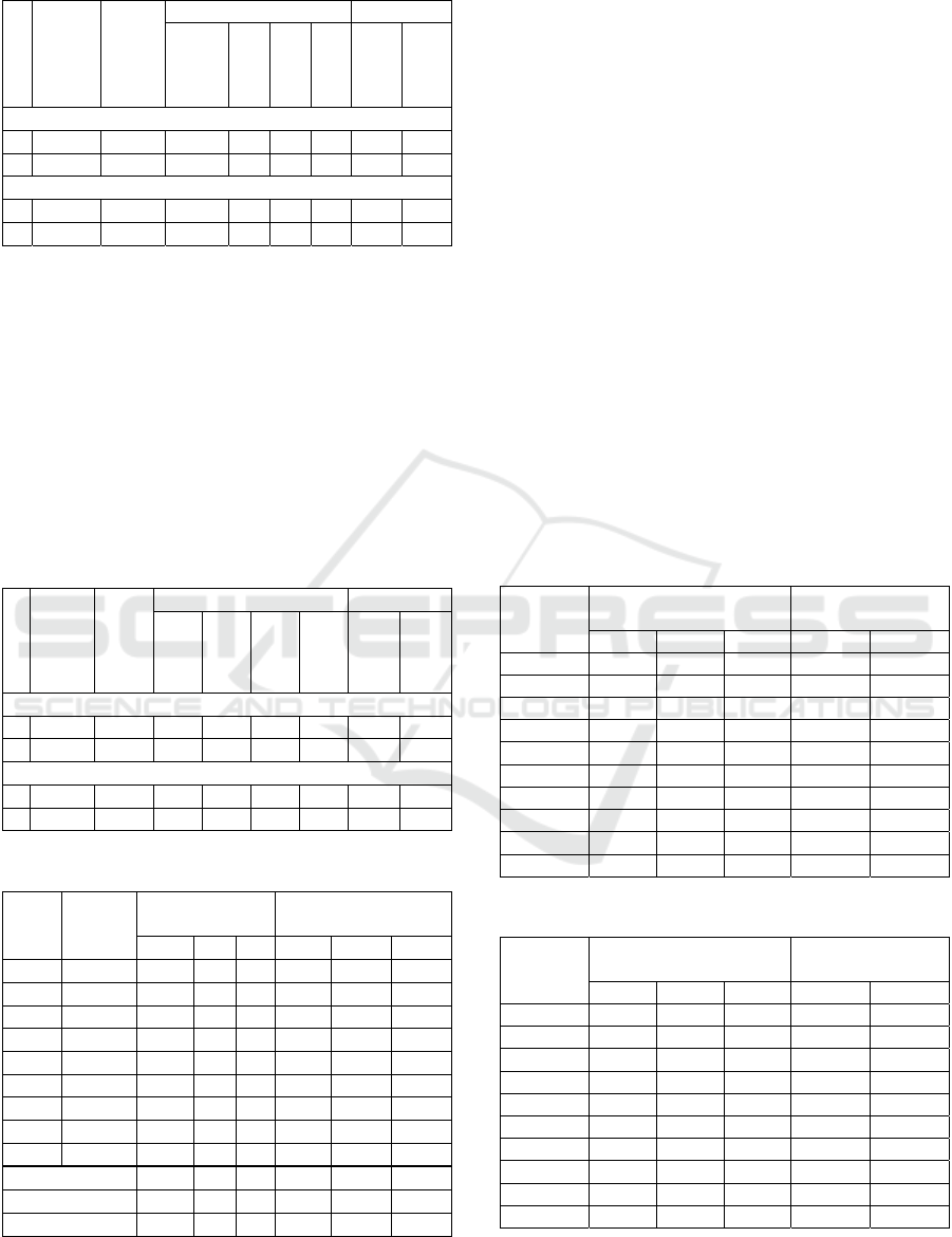
Table 2: Computational time analysis for D01 sequence.
Source views
Empty
pixels
Iterative (I)
Anal
y
sis Processin
g
Naïve
Corner
RowCol
Tiles
Selection
Merging
Sin
g
le-threade
d
p
rocessin
g
time [ms]
2 3479 40.94 1.34 3.93 4.68 2.24 1.09 1.19
1 120019 525.16 158.45 4.24 5.00 5.23 2.10 3.31
Multi-threade
d
p
rocessing time [ms]
2 3479 24.01 1.69 2.33 2.24 0.87 0.25 0.26
1 120019 237.57 178.06 3.02 2.33 1.82 0.38 0.52
In the case of the analysis stage, the naïve
approach is reasonably fast only if the number of
missing pixels is low. However, it can be very slow
for a higher number of missing pixels and does not
scale with the number of threads (due to memory
bandwidth starvation). Corners originating and rows-
columns approaches offer more consistent and
predictable results and noticeable speedup for parallel
execution. The tile-based approach is the fastest for
all multithreaded tests and offers competitive
performance for the single-threaded variant.
Table 3: Computational time analysis for A01 sequence.
Source views
Empty
pixels
Iterative (I)
Anal
y
sis Processin
g
Naïve
Corner
RowCol
Tiles
Selection
(S)
Merging
(M)
Single-threade
d
p
rocessing time [ms]
2 134887 308.84 11.86 15.31 18.72 11.98 7.16 7.41
1 522251 881.23 47.85 16.21 20.36 20.17 11.14 15.71
Multi-threade
d
p
rocessin
g
time [ms]
2 134887 160.75 17.13 9.75 13.96 5.10 2.49 3.40
1 522251 433.29 58.60 9.75 14.07 9.92 3.53 5.27
Table 4: Inpainting computational time for all sequences.
Seq
Empty
pixels
(avg)
Inpainting time
[ms]
Inpainting time per
p
ixel [ns]
I S M I S M
A01 134904 166.3 8.99 9.31 1232.7 66.66 69.01
C01 225629 491.6 8.88 8.25 2178.9 39.34 36.56
C02 892321 1749.9 6.21 7.49 1961.1 6.96 8.40
D01 2448 22.9 1.02 0.96 9338.9 416.26 390.37
J01 36968 47.4 1.34 1.52 1281.8 36.27 41.00
J04 44346 60.2 2.07 1.83 1357.7 46.75 41.28
L01 114944 142.1 1.66 1.31 1236.2 14.41 11.40
L03 176439 223.6 2.00 3.09 1267.2 11.36 17.48
W02 38010 36.4 2.03 2.85 957.3 53.36 75.07
Av
g
. ERP 802.6 8.03 8.35 1790.9 37.65 37.99
Av
g
. Pers
p
ective 88.8 1.69 1.93 2573.2 96.40 96.10
All 326.7 3.80 4.07 2312.4 76.82 76.73
When inpainting processing is considered, the
“merging” approach (referred to as “M”) is slower
than the simpler “selection” method (referred to as
“S”), but the difference can be treated as negligible.
In Table 4 the summary for all test sequences was
presented. In this case, the fastest possible analysis
algorithm (tile-based) was used, and combined times
for analysis and processing were presented. All
results were gathered using multithreaded processing,
as the authors consider this scenario more relevant. In
general, the proposed algorithm is ~80 times faster
than the reference, iterative approach.
5.3 Quality Evaluation
In the quality evaluation, a virtual view was
synthesized using two real views. Results of the
objective quality evaluation are presented in Tables 5
and 6, separately for each test sequence. As presented,
both proposed fast inpainting methods allow for
achieving similar quality as a more sophisticated and
complicated iterative approach, both in terms of WS-
PSNR and IV-PSNR.
Table 5: Quality of rendered virtual views: WS-PSNR.
Seq
WS-PSNR [dB]
ΔWS-PSNR
[dB]
(
com
p
ared to I
)
I S M S M
A01 31.74 31.61 31.74
–
0.13
–
0.00
C01 37.65 37.81 37.92 0.16 0.27
C02 23.73 22.67 23.66
–
1.07
–
0.07
D01 37.64 37.62 37.62
–
0.01
–
0.01
J01 29.41 29.18 29.48
–
0.23 0.07
J04 28.12 27.90 28.16
–
0.21 0.05
L01 28.86 28.80 28.80
–
0.06
–
0.06
L03 26.69 26.26 26.54
–
0.43
–
0.15
W02 29.08 28.74 28.94
–
0.34
–
0.13
Avera
g
e 30.32 30.07 30.32
–
0.26
–
0.00
Table 6: Quality of rendered virtual views: IV-PSNR.
Seq
IV-PSNR [dB]
ΔIV-PSNR [dB]
(
com
p
ared to I
)
I S M S M
A01 46.14 46.10 46.24
–
0.04 0.10
C01 47.44 47.66 47.64 0.21 0.20
C02 32.90 31.94 33.13
–
0.96 0.23
D01 47.52 47.47 47.44
–
0.05
–
0.07
J01 38.13 37.82 38.12
–
0.30
–
0.01
J04 37.20 37.05 37.33
–
0.15 0.12
L01 41.89 41.59 41.59
–
0.30
–
0.30
L03 32.23 31.77 32.09
–
0.46
–
0.14
W02 42.63 41.84 42.16
–
0.79
–
0.46
Avera
g
e 40.67 40.36 40.64
–
0.31
–
0.04
Subjectively, rendered virtual views are similar
although the characteristics of the artifacts differ
VISAPP 2024 - 19th International Conference on Computer Vision Theory and Applications
698

between various methods (Fig. 7). In the iterative
approach, disocclusions are blurred, what is plausible
in smooth areas, but distractive in areas containing
edges (e.g., a building corner in Cyberpunk
sequence). Both fast inpainting methods preserve
edges much better due to horizontal and vertical
image analysis performed before the inpainting. It is
worth noting that the quality achieved by the
proposed algorithm is similar to the reference
iterative approach, however, the computation time is
about 100 times shorter (~4ms for proposed vs 326
for iterative).
5.4 Comparison Against Widely Used
General Inpainting Algorithms
The comparison of the proposed approach against
state-of-the-art inpainting techniques was particularly
challenging. There are several algorithms designed
for the inpainting of synthesized views (Daribo,
2010), (Buyssens, 2017), (Cho, 2017), however
software with their implementations is not available.
Therefore, for this comparison, we decided to choose
two inpainting algorithms based on availability
(widespread software libraries) and a decent quality
of implementation. The first is an inpainting
algorithm based on the biharmonic equation
(Damelin, 2018) (“[Dam]”) with an implementation
available in a widely recognized “scikit-image”
image processing library. The second candidate is an
algorithm based on the fast marching method (Telea,
2004) (“[Tel]”) with an implementation available in
the widely used OpenCV library.
Table 7: Inpainting computational time for all sequences.
Seq
Empty pixels
(average)
In
p
aintin
g
time
p
e
r
frame [ms]
M [Dam] [Tel]
A01 134904 9.31 2406 27877
C01 225629 8.25 13489 7791
C02 892321 7.49 > 10 min 27723
D01 2448 0.96 320 104
J01 36968 1.52 511 465
J04 44346 1.83 1483 2093
L01 114944 1.31 15111 228
L03 176439 3.08 16624 1810
W02 38010 2.85 583 8156
Avera
g
e
(
excl. C02
)
4.07 6316 8472
In the case of the C02 sequence, the algorithm
(Damelin, 2018) was excluded due to excessive
computation time exceeding 10 minutes per frame
thus making it useless for real-time purposes. The
detailed result of computational time analysis is
presented in Table 7. On average, the investigated
algorithm is about three orders of magnitude slower
than the proposed one (they process frame in several
seconds in contrast to several milliseconds for the
proposed one).
Table 8: Quality of rendered virtual views: WS-PSNR.
Seq
WS-PSNR [dB]
ΔWS-PSNR [dB]
(compared to I)
M [Dam] [Tel] [Dam] [Tel]
A01 31.74 30.95 31.18 0.79 0.56
C01 37.92 35.92 35.84 2.00 2.08
C02 23.66 --- 21.56 --- 2.10
D01 37.62 37.46 37.35 0.16 0.27
J01 29.48 28.32 29.01 1.16 0.47
J04 28.16 25.3 25.76 2.86 2.40
L01 28.8 28.48 28.66 0.32 0.14
L03 26.54 26.61 26.11
–
0.07 0.43
W02 28.94 28.43 28.41 0.51 0.53
Avg excl. C02 31.15 30.18 30.29 0.97 0.86
The results of inpainting quality evaluation in
terms of WS-PSNR and IV-PSNR were presented in
Table 8 and Table 9. In 95% of test cases, the
proposed algorithm offered better quality of inpainted
pictures when compared to (Damelin, 2018) and
(Telea, 2004). On average, the objective quality
achieved by the proposed algorithm was ~0.9 dB
better in terms of WS-PSNR and ~1.05 dB better in
terms of IV-PSNR.
Table 9: Quality of rendered virtual views: IV-PSNR.
Seq
IV-PSNR [dB]
ΔIV-PSNR [dB]
(compared to I)
M [Dam] [Tel] [Dam] [Tel]
A01 46.24 45.55 46.35 0.69
–
0.11
C01 47.64 45.63 45.31 2.01 2.33
C02 33.13 --- 30.29 --- 2.84
D01 47.44 47.05 46.83 0.39 0.61
J01 38.12 37.38 37.19 0.74 0.93
J04 37.33 34.95 34.68 2.38 2.65
L01 41.59 39.85 40.94 1.74 0.65
L03 32.09 32.04 31.26 0.05 0.83
W02 42.16 41.74 41.59 0.42 0.57
Avg excl. C02 41.58 40.52 40.52 1.05 1.06
5.5 Real-Time View Rendering vs.
State-of-the-Art View Rendering
In the last experiment, the entire view rendering
algorithm (Stankowski, 2023), which includes the
proposed inpainting technique was compared to the
state-of-the-art view synthesis software – RVS (ISO,
2018). The results – both computational time and
objective quality – are reported in Table 10.
Fast and Reliable Inpainting for Real-Time Immersive Video Rendering
699
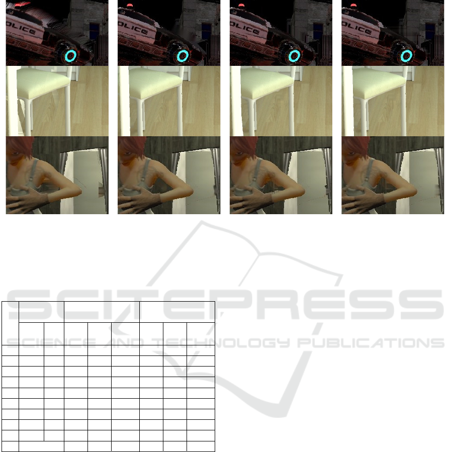
Figure 7: Fragments of views rendered using real-time synthesizer (Stankowski, 2023) with different inpainters (columns 2 –
4), compared to views rendered using state-of-the-art view synthesizer – RVS (ISO, 2018). Sequences (from top): C02, J01,
W02.
Table 10: The real-time view synthesizer (Stankowski,
2023) with proposed fast inpainting vs. state-of-the-art RVS
(ISO, 2018).
Sequence
Rendering
time [ms]
WS-PSNR [dB] IV-PSNR [dB]
RVS
Prop.
RVS
Prop.
Δ
RVS
Prop.
Δ
A01
15885 39.7 31.90 31.73
–
0.17 45.04 46.24 1.20
C01
15547 36.9 37.55 37.92 0.37 46.93 47.64 0.71
C02
7878 19.0 22.63 23.66 1.03 31.45 33.13 1.68
D01
3838 8.8 38.51 37.62
–
0.89 48.08 47.44
–
0.64
J01
3370 7.7 28.83 29.48 0.65 37.02 38.12 1.10
J04
3723 7.8 27.14 28.16 1.02 36.68 37.33 0.65
L01
3355 8.4 29.70 28.80
–
0.90 40.77 41.59 0.82
L03
3285 8.1 26.90 26.54
–
0.36 32.31 32.09
–
0.22
W02
3437 8.2 29.40 28.94
–
0.46 41.60 42.16 0.56
Avg
30.28 30.32 0.03 39.99 40.64 0.65
In terms of subjective quality, the real-time view
synthesizer slightly outperforms the RVS, especially
in disoccluded regions, where RVS tries to preserve
continuity between reprojected pixels (using triangle-
based reprojection (Fachada, 2018)) while all tested
inpainting methods do not introduce distractive
artifacts (Fig. 7).
6 CONCLUSIONS
In the paper, we have presented an efficient inpainting
method, which can be used in the virtual view
rendering in a practical, real-time immersive video
system. The proposal allows for achieving a high
Quality of Experience for an immersive video system
user while requiring extremely short computational
time. The proposed approach is based on splitting the
inpainting process into two highly parallelizable
stages: view analysis and hole filling.
The experimental results show that in a typical
case, where a FullHD virtual view is rendered using
two input views, the proposed inpainting requires less
than 2 ms per frame (result averaged over 6 test
sequences). Moreover, the objective and subjective
quality of rendered views is similar to using more
sophisticated and time-consuming inpainting
methods.
The proposal was implemented within a real-time
CPU-based virtual view synthesizer (Stankowski,
2023) developed by the authors of this manuscript,
showing that it is possible to obtain vastly fast
rendering, allowing the development of a practical,
consumer immersive video system.
ACKNOWLEDGEMENTS
This work was supported by the Ministry of
Education and Science of the Republic of Poland.
RVS
(
ISO, 2018
)
Iterative in
p
aintin
g
(
I
)
Selection in
p
aintin
g
(
S
)
Mer
g
in
g
in
p
aintin
g
(
M
)
VISAPP 2024 - 19th International Conference on Computer Vision Theory and Applications
700

REFERENCES
Barnes, C., et al. (2009). “Patch-Match: a randomized
correspondence algorithm for structural image editing,”
ACM Tr. on Graphics, vol. 28, no. 3.
Bertalmio, M., et al. (2000). “Image inpainting,”
SIGGRAPH 2000, New Orlean, USA.
Boissonade, P., Jung, J. (2018). “Proposition of new
sequences for Windowed-6DoF experiments on
compression, synthesis, and depth estimation,” Doc.
ISO/IEC JTC1/SC29/WG11 MPEG/M43318.
Boyce, J., et al. (2021). “MPEG Immersive Video Coding
Standard,” Proc. IEEE 119 (9), pp. 1521-1536.
Buyssens, P., et al. (2017). “Depth-guided disocclusion
inpainting of synthesized RGB-D images,” IEEE Tr. on
Image Proc., vol. 26, no. 2, pp. 525-538.
Cho, J.H., et al. (2017). “Hole filling method for depth
image based rendering based on boundary decision,”
IEEE Signal Proc. Letters 24 (3), pp. 329-333.
Criminisi, A., et al. (2004). “Region filling and object
removal by exemplar-based image inpainting,” IEEE
Tr. on Image Proc. 13 (9), pp. 1200-1212.
Damelin, S.B., Hoang, N. (2018). “On Surface Completion
and Image Inpainting by Biharmonic Functions:
Numerical Aspects,” Int. Journal of Mathematics and
Mathematical Sciences, 2018 (3950312).
Daribo, I., et al. (2010). “Depth-aided image inpainting for
novel view synthesis,” MMSP, Saint-Malo, France.
Domański, M. et al. (2016). “Multiview test video
sequences for free navigation exploration obtained
using pairs of cameras,” Doc. ISO/IEC
JTC1/SC29/WG11, MPEG M38247.
Doré, R. (2018). “Technicolor 3DoF+ test materials,”
ISO/IEC JTC1/SC29/WG11 MPEG, M42349, San
Diego, CA, USA.
Doré, R., et al. (2020). “InterdigitalFan0 content proposal
for MIV,” Doc. ISO/IEC JTC1/SC29/ WG04 MPEG
VC/ M54732, Online.
Doyen, D., et al. (2018). “[MPEG-I Visual] New Version
of the Pseudo-Rectified Technicolor painter Content,”
Doc. ISO/IEC JTC1/SC29/WG11 MPEG/M43366.
Dziembowski, A., et al. (2016). “Multiview Synthesis –
improved view synthesis for virtual navigation,” PCS
2016, Nuremberg, Germany.
Dziembowski, A., Domański, M. (2018). “Adaptive color
correction in virtual view synthesis,” 3DTV Conf.
2018, Stockohlm – Helsinki.
Dziembowski, A., Stankowski, J. (2018). “Real-time CPU-
based virtual view synthesis,” 2018 ICSES Conf.,
Kraków, Poland.
Dziembowski, A., et al. (2019). “Virtual view synthesis for
3DoF+ video,” PCS 2019, Ningbo, China.
Dziembowski, A., et al. (2022). “IV-PSNR—The Objective
Quality Metric for Immersive Video Applications,”
IEEE T. Circ. & Syst. V. Tech. 32 (11).
Fachada, S., et al. (2018). “Depth image based view
synthesis with multiple reference views for virtual
reality,” 3DTV-Conf, Helsinki, Finland.
Fujii, T., et al. (2006). “Multipoint measuring system for
video and sound – 100-camera and microphone
system,” IEEE Int. Conf. on Mult. and Expo.
Huang, H., et al. (2019). “System and VLSI implementation
of phase-based view synthesis,” 2019 ICASSP
Conference, Brighton, UK.
ISO. (2018). “Reference View Synthesizer (RVS) manual,”
Doc. ISO/IEC JTC1/SC29/WG11 MPEG, N18068.
ISO. (2023). “Common test conditions for MPEG
immersive video,” ISO/IEC JTC1/SC29/WG04 MPEG
VC, N0332, Antalya, Turkey.
Jeong, J.Y., et al. (2021). “[MIV] ERP Content Proposal for
MIV ver.1 Verification Test,” ISO/IEC JTC1/
SC29/WG04 MPEG VC, M58433, Online.
Khatiullin, A., et al. (2018). “Fast occlusion filling method
for multiview video generation,” 3DTV Conf. 2018,
Stockholm, Sweden.
Kroon, B. (2018). “3DoF+ test sequence ClassroomVideo,”
ISO/IEC JTC1/SC29/WG11 MPEG, M42415, San
Diego, CA, USA.
Lai, Y., et al. (2017). “Three-dimensional video inpainting
using gradient fusion and clustering,” ICNC-FSKD
Conf. 2017, Guilin, China.
Levin, A., et al. (2003). “Learning how to inpaint from
global image statistics,” 9th Int. Conf. on Computer
Vision, Nice, France.
Li, Y., et al. (2019). “A real-time high-quality complete
system for depth image-based rendering on FPGA,”
IEEE T. Circ&Sys. for V. Tech. 29(4), pp. 1179-1193.
Liu, H., et al. (2012). “Global-background based view
synthesis approach for multi-view video,” 3DTV Conf.
2012, Zurich, Switzerland.
Luo, G., Zhu, Y. (2017). “Foreground removal approach
for hole filling in 3D video and FVV synthesis,” IEEE
Tr. Circ. & Syst. Vid. Tech. 27 (10), pp. 2118-2131.
Mao, Y., et al. (2014). “Image interpolation for DIBR view
synthesis using graph Fourier transform,” 3DTV Conf.
2014, Budapest, Hungary.
Microsoft Developer Network Library. (2020). Acquiring
high-resolution time stamps. https://msdn.microsoft.
com/enus/library/windows/desktop/dn553408.
Mieloch, D., et al. (2020). “Depth Map Estimation for Free-
Viewpoint Television and Virtual Navigation,” IEEE
Access, vol. 8, pp. 5760-5776.
Mieloch, D., et al. (2020). “[MPEG-I Visual] Natural
Outdoor Test Sequences,” Doc. ISO/IEC JTC1/
SC29/WG11 MPEG/M51598, Brussels.
Mieloch, D., et al. (2023). “[MIV] New natural content –
MartialArts,” ISO/IEC JTC1/SC29/WG04 MPEG VC,
M61949, Online.
Müller, K., et al. (2011). “3-D Video Representation Using
Depth Maps,” Proc. IEEE 99 (4), pp. 643-656.
Nonaka, K., et al. (2018). “Fast plane-based free-viewpoint
synthesis for real-time live streaming,” 2018 VCIP
Conf., Taichung, Taiwan, pp. 1-4.
Oh, K.J., et al. (2009). “Hole filling method using depth
based inpainting for view synthesis in free viewpoint
television and 3-D video,” PCS 2009, Chicago.
Fast and Reliable Inpainting for Real-Time Immersive Video Rendering
701

Stankiewicz, O., et al. (2018). “A free-viewpoint television
system for horizontal virtual navigation,” IEEE Tr. on
Multimedia 20 (8), pp. 2182-2195.
Stankowski, J., Dziembowski, A. (2023). “Massively
parallel CPU-based virtual view synthesis with atomic
z-test,” WSCG 2023 Conf., Pilsen, Czechia.
Sun, Y., et al. (2017). “Weighted-to-Spherically-Uniform
Quality Evaluation for Omnidirectional Video,” IEEE
Signal Processing Letters 24.9(2017):1408-1412.
Tanimoto, M., et al. (2012). “FTV for 3-D Spatial
Communication,” Proc. IEEE 100, pp. 905-917.
Tao, L., et al. (2021). “A Convenient and High-Accuracy
Multicamera Calibration Method Based on Imperfect
Spherical Objects,” IEEE Tr. Instr. & Meas. 70.
Telea, A. (2004). “An image inpainting technique based on
the fast marching method,” Journal of Graphics Tools 9
(1), pp. 23-34.
Tezuka, T., et al. (2015). “View synthesis using superpixel
based inpainting capable of occlusion handling and hole
filling,” PCS 2015, Cairns, Australia.
Vadakital, V.K.M., et al. (2022). “The MPEG Immersive
Video Standard—Current Status and Future Outlook,”
IEEE MultiMedia 29 (3), pp. 101-111.
Wang, O., et al. (2011). “StereoBrush: interactive 2D to 3D
conversion using discontinuous warps,” 8th
Eurographics Symposium on Sketch-Based Interfaces
and Modelling, Vancouver, Canada.
Wien, M., et al. (2019). “Standardization status of
immersive video coding,” IEEE J. Emerg. and Sel. Top.
in Circ. and Syst. 9 (9).
Xiang, S., et al. (2013). ”A gradient-based approach for
interference cancelation in systems with multiple
Kinect cameras,” in Proc. IEEE Int. Symp. Circuits
Syst. (ISCAS), Beijing, China, pp. 13–16.
Yao, C., et al. (2014). “Depth map driven hole filling
algorithm exploiting temporal correlation information,”
IEEE Tr. on Broadcasting, vol. 60, no. 2, pp. 510-522.
Zinger, S., et al. (2010). “Free-viewpoint depth image based
rendering,” J. of Visual Communication and Image
Representation 21 (5-6), pp. 533-541.
VISAPP 2024 - 19th International Conference on Computer Vision Theory and Applications
702
