
EMplifier: Hybrid Electromagnetic Probe for Side Channel and Fault
Injection Analysis
Fabrizia Marrucco, Mosabbah Mushir Ahmed, Bechir Bouali and Alieeldin Mady
Qualcomm Technologies, Cork, Ireland
Keywords: Hardware Security, Offensive Security, EM-FI, SCA.
Abstract: Electromagnetic Fault Injection (EM-FI) analysis is increasingly emerging as an effective technique to bypass
countermeasure and/or leak sensitive information by injecting fault during the execution of sensitive
asset/operation. EM-FI analysis becomes an essential requirement for obtaining product security certification,
whenever high assurance is claimed. The coils represent an integral part of the EM probe design. Therefore,
it is important to focus on the practical study of coil design that accentuate the efficiency of EM capture and
emission. In this work we tried to optimize the design of a hybrid coil (called EMplifier) that can efficiently
sense the EM emissions and inject the fault, enabling a guided fault injection analysis with a single coil. This
state-of-art investigates the various important coil parameters that can be used in a hybrid scenario of both
capturing and emitting EM signals. Such design is useful in practical EM-FI setup where identifying the exact
injection location over the chip is a key factor towards successful attacks.
1 INTRODUCTION
High security assurance is rapidly becoming an
industrial requirement for assets connected to
internet, ranging from smart garage door openers,
smart home locks, smart TVs, and handsets to
automobiles. These connected Internet-of-things
(IoT) and Cyber-Physical Systems (CPS) link
together devices that were previously isolated, where
critical application and infrastructure enforce the high
assurance security requirements (Li et al., 2016).
Providing high security assurance starts by
building a highly resilient hardware, which acts as a
root of trust for software components on top
(Mansour & Lauf, 2020). Hardware is produced in a
mass-production with a static security footprint,
where a successful attack on a single device can lead
to reducing resiliency of applications use this
hardware. Software patching has an easier process
than hardware in case of vulnerability identification,
hence industry has been enforcing a high security
assurance requirement for security critical
application, such as banking, payment terminals,
passport. Common Criteria certification (CC) scheme
(Common Criteria, 2022) was introduced to
formulate a security evaluation standardization by
levelling the security assurance level using
Evaluation Assurance Level (EAL). CC scheme has
introduced a disruptive change in the industrial
landscape, where hardware security requirements
were benchmarked against the application domain
used by this hardware, e.g., passport and banking
applications require EAL7 to reflect the maximum
assurance level.
Hardware security evaluation considers two main
attack categories: Side-Channel Analysis (SCA) and
Fault injection (FI) attacks. Side-channel analysis
(Koeune & Standaert, 2005) aims to extract
secrets/keys from chips through measuring and
analysing hardware physical parameters, such as
power consumption, response time, and EM
emission. Fault injection analysis (Barenghi et al.,
2012) aims to gain privileges or extract secrets/keys
by modifying the device execution flow by injecting
faults using different medium, such as voltage/clock
glitching, body-biasing (BBI), EM-FI and laser
emissions (L-FI).
EM-FI, BBI and L-FI are classified as localised-
FI attacks, where fault in precisely injected on the
die’s backside to perturbate targeted asset in isolation
of the surrounded subsystems/assets. The isolation
nature of the localised-FI leads to a high precision and
effective perturbation, which increasingly emerges as
a common method in evaluating System-On-Chip
(SoC) security resiliency. Within localised-FI, EM-FI
Marrucco, F., Ahmed, M., Bouali, B. and Mady, A.
EMplifier: Hybrid Electromagnetic Probe for Side Channel and Fault Injection Analysis.
DOI: 10.5220/0012431800003648
Paper published under CC license (CC BY-NC-ND 4.0)
In Proceedings of the 10th International Conference on Information Systems Security and Privacy (ICISSP 2024), pages 815-822
ISBN: 978-989-758-683-5; ISSN: 2184-4356
Proceedings Copyright © 2024 by SCITEPRESS – Science and Technology Publications, Lda.
815

has gained a significant recognition by offensive
security community due to the attack cost efficient,
where an optimal compromise is achieved between
attack cost versus effectiveness (Barenghi et al.,
2012; Dehbaoui et al., 2012).
Developing EM-FI attack follows multiple stages,
where identifying the optimal injection location over
the die is a key stage towards a successful attack.
Typically, side-channel EM leakage is useful to
identify the optimal location of the injection, based on
the maximum leakage location for the targeted assets.
Even though EM medium is used for both side
channel leakage and fault injection, two different
probes will be required with manual switching.
Passive EM sensing probe is used to evaluate the EM
leakage, whereas fault is injected by active EM probe.
Switching between these two probes is challenging
due to the required micrometre scale precision
needed. The use of an XYZ table can help in
obtaining an approximate location but doesn’t allow
us to have a high precision.
While certain studies have investigated into
optimizing the design of EMFI coils and others have
focused on enhancing sensing coils designs, no prior
research has attempted to identify an optimal design
that consider both aspects. In this work our primary
focus has been on developing a hybrid coil, called
EMplifier, where EMplifier aims to efficiently
monitor EM emission (i.e., passive EM-probe) and
inject EM signal (i.e., active EM-probe).
Although the probe for both SCA and FI requires
certain amount circuit elements like amplifier,
switches, pulse generator etc., the design of other
parts of the probes is not in the scope of this work.
The main contributions are manyfold, listed as
follows:
Comprehension of design parameters of the
probe that affect the FI and SCA capability.
Design of a novel hybrid EM-probe coils,
enabling multi-stage FI attack.
Experimental study for optimising EMplifier
design parameters.
2 RELATED WORKS
We can identify two types of EM-FI platforms. The
single probe type requires two different probes used
for passive and active operations. The dual EM-
probe, proposed in this paper, is used to perform EM
injections and side-channel measurements.
Regarding the design of EM-FI probes several
research have been conducted. For instance, in (Gaine
et al., 2022) the characteristics of EM-probe to
increase the effectiveness of the EM injection while
limiting the requirement of high voltages has been
studied. The key characteristics are selecting a soft
high permeability ferrite for probe's core and
overlaying the probe coil turns. Moreover,
ChipShouter (NAE-CW520, n.d.) is widely used
EMFI platform in hardware research community. The
tool can generate up to 500 V. The probes provided
with the tool are 1 mm or 4 mm in diameter. The core
is made of ferrite. Also, SiliconToaster (Abdellatif &
Heriveaux, 2020) is a custom EM-FI platform. The
tool can produce a pulse of 1200 V. The EM probe
used with SiliconToaster is built from a flat coil of 6.6
mm diameter with 9 turns. The core is made of ferrite
with a 4.5 mm diameter and 10 mm length. Despite
this, the only commercial solution capable of
injecting EM pulses and performing EM
measurement simultaneously using the same probe is
the EM-FI Transient Probe with Adjustable Pulse
width (EM-FI Transient Probe Adjustable Pulse
Width - Riscure, n.d.) that can generate up to 100 V
(power over coil). Nevertheless, no public details
related to characteristics of the probe design have
been published.
In comparison to the related studies, this work
focusses on the fundamental aspects of EM probe i.e.,
the coil. A thorough investigation is made to
understand the important characteristics of the coil
pertaining to both FI and SCA. Furthermore, in
comparison to this existing hybrid commercial design
(EM-FI Transient Probe Adjustable Pulse Width -
Riscure, n.d.), this work investigates the coil aspect
of the EM-FI probe, whereas the existing commercial
tools do not give the explicit detail of the different
aspects of the probe that contributes to the hybrid
nature. On the other hand, in applications where
precise location of the EM emission is needed can be
achieved by recording the XYZ co-ordinate, but such
an architecture still requires changing the probes
manually that can be expensive in terms of time and
mechanical adjustments/errors. EMpilfier design can
inhibit the use of such multiple probe settings.
3 PRELIMINARIES
The two main aspects that determines the operation
of the EM probe coils are:
EM interaction mechanisms
Field region
First, the coupling laws are based on Biot-
Savart’s law and Faraday’s law. The first is a
ICISSP 2024 - 10th International Conference on Information Systems Security and Privacy
816

fundamental quantitative relationship between an
electric current I and the magnetic flux B that it
produces. This law is the basis of the phenomenon
whereby, having obtained a current through the coil,
it generates a magnetic field proportional to the
current that generated it. The generated magnetic
field can then generate an induced current according
to the well-known Faraday's law (Kinsler, 2020;
Oliveira & Miranda, 2001). These laws are applicable
for both SCA (also referred as signal sensing in this
paper) and FIA (fault injection attacks).
Secondly, the field of interest for this work and in
general FI and SCA testing is the near-field region.
This region has complex characteristic and
approximations rules. Consequently, obtaining
accurate simulation is particularly complex (Nikitin
et al., 2007) and changes in the design of the coils can
significantly affect its efficiency in terms of FIA and
SCA. Moreover, is not possible to have a complete
control over all the parameters that will affect the FIA
success rate or the SCA sensitivity.
3.1 Parameters Characteristics
Utilizing the aspects or features stated above, a set of
parameters are selected that are utilized for the
effective design of the EM probes. The design of the
probe is categorized into two parts: (1) selection of
parameters, (2) design and test. For the first part,
parameters are classified under certain sub-categories
- independent parameters set (IPS) and dependent
parameter set (DPS). The characteristic of the IPS is
that they consist of variables that can be controlled
while designing the probe. This set of parameters
could include dimensions of the solenoid, the spacing
between the coils, the number of turns, and the
material used. The outcome of IPS decides the DPS.
Some of the DPS observed during the EM probe
design and testing are the signal amplitude, resonant
frequency, sensitivity etc.
Due to the complexity of simulating the
interaction between the EM coil and the DUT, it is not
possible to show with high precision how changing
the values of the IPS will affect all the DPS values.
Therefore, before going into the design phase, a
procedure has been conducted and can be summarize
with the Algorithm 1. This procedure has the aim of
evaluating if the values chosen for the IPS will make
the DPS values correspond with the expected
requirements, ‘test_req’ in the Algorithm 1. Due to
the hybrid nature of the EM probe, it is necessary that
the choice of IPS is significative for both SCA and
FIA or, in other words, that IPS(FI) and IPS(SCA)
have interjection.
A list of important sets of DPS and IPS taken into
consideration while designing the probe are
highlighted in Table 1. Observing from Table 1, IPS
are approximately common for both SCA and FIA
although the DPS can vary. Therefore, this
interjection is decisive in the choice of design
parameters as they will correspond to the common
IPS.
3.2 DPS Parameters Brief
In this section, some of the important DPS that are
critical to be understood for the design of hybrid coil,
are briefly discussed.
Damping of the Injected Current. Ideally for FI it
is better to have a critically damped response refer
that will result in a value that can be approximated as
in (1) if the circuit can ideally be represented as an
RLC circuit (Beckers et al., 2020), as shown in:
=
(
)
(1)
here, I is the current, V
0
is the initial voltage, R
and L are resistance and inductor respectively
(Dannehl et al., 2011). Over-damping would increase
the pulse-width, while under-damping results in
ringing. The amount of coupling between the probe
and the device itself changes with the frequency of
the EM pulse.
Coupling. Different frequencies can result in
different values of coupling effecting the induced
current and overall system behaviour. This frequency
dependency complicates the study and
comprehension of the EM-pulse injection process.
Directivity. It measures the concentration of the
radiation pattern of the probe in a particular direction.
A higher directivity indicates a better focus and
signal-to-noise ratio (SNR) values of the field /
signals. It applies to both FI and SC equally. This
makes it less sensitive to noise (or signals) coming
from other directions or sources.
Algorithm 1: Selection of parameters.
1.procedure: CalculateDPSDecideIPS(test_req’):
2. select the test requirements ‘test_req’
3. check if DPS = test_req’ |
4. if test_req meets certain conditions:
5. DPS = calculate_DPS_based_on_’test_req’
6. if criteria_for_DPS_are_fulfilled(DPS):
7. IPS = make_decision_based_on_DPS(DPS)
8. else
9. reset IPS
10. end procedure
EMplifier: Hybrid Electromagnetic Probe for Side Channel and Fault Injection Analysis
817
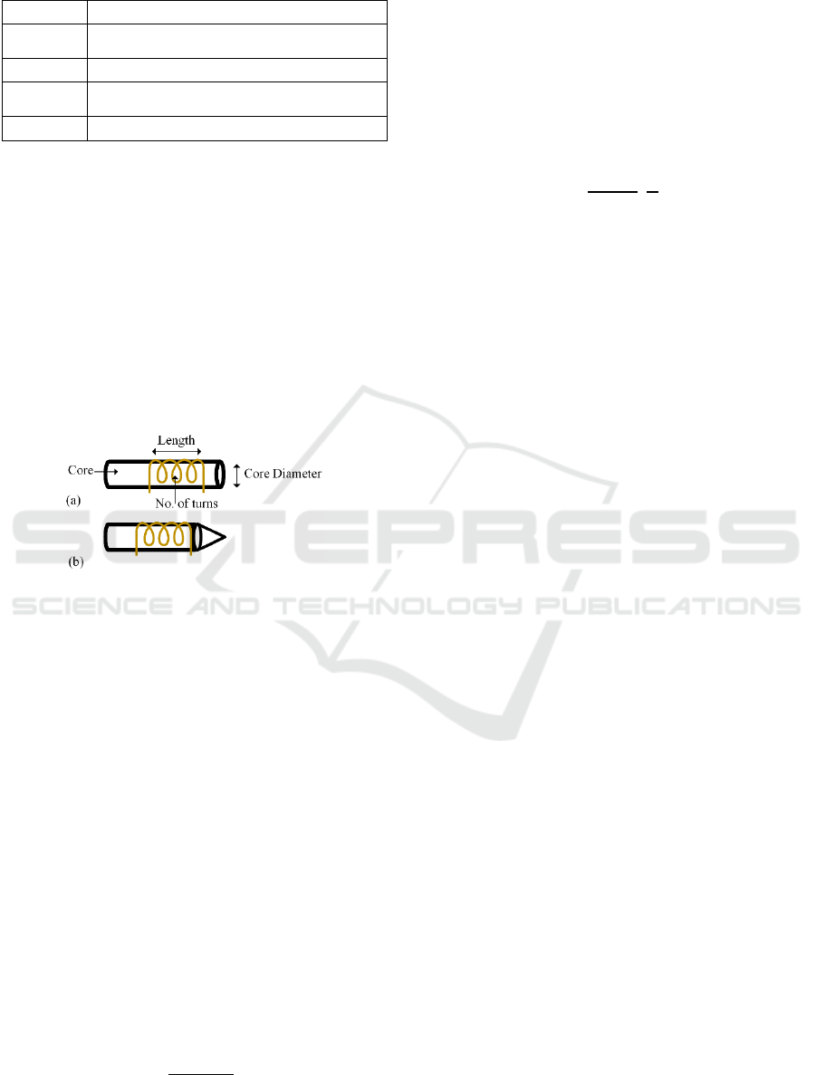
Table 1: Parameters example list for the probe design.
Parameter Variables
DPS (SCA) Signal-to-noise ratio (SNR), Directivity,
Coupling between DUT and probe
IPS (SCA) No. of turns, Type of core, Diameter of the coil
DPS (FI) Power of the injected EM field, Coupling
between DUT and probe, Directivity, Damping
IPS (FI) No. of turns, Type of core, Diameter of the coil
4 EMPLIFIER DESIGN
The efficiency of a hybrid EM probe’s coil is
determined by some important parameters that define
the limitations and range of its working frequency,
power etc. Those independent values, the IPS effects
DPS values and are the one we can control when
designing the probe. From the selection phase and the
requirements (test_req from Algorithm 1), several
important aspects (that can be part of IPS) have been
identified. These are also illustrated in Figure 1.
Figure 1: Different IPS sets used during the design of the
hybrid EM-probe. (a) Flat shape (b) Sharp-tip.
4.1 Number of Turns (N)
Number of turns (N) is an important characteristic of
the probes, changing its value effects both FI and SC
capability. In one the first studies on the N required
for FI, it is shown, with the help of simulation results,
that only a single loop (turn) would be sufficient
however (Omarouayache et al., 2013), as research
progressed in this area, it has been observed that one
loop does not seem to be the most effective solution
in the case of FI (Ordas et al., 2017).
As an important aspect for FI, the goal is not to
generate the highest magnetic field amplitude, but to
preferably maximize the rate of change of H-field at
the rising and falling edges of the pulse as it will
affect the induced current value. When the number
of windings increases, the inductance (L) is expected
to rise quadratically with the number of windings
(Beckers et al., 2020).
=
(2)
From (2), kµ
0
determines the material properties –
magnetic permeability, the other part of equation
N
2
A/l shows the geometrical characteristics – number
of turns, area, length of solenoid respectively. Going
back to (2) it can be observed that with increased L,
the current (I) decreases, but at the same time it
impacts positively for the B refer to (3), where R is
the parameter that determines the radius of the core
(solenoid).
=
μ
2
[
1
]
(3)
In general, it could be possible to assume that if N
increases, under certain limits, the two effects will
slightly compensate each other (Caciagli et al., 2018).
Also, damping of the circuit depends on L, the time
window of the interaction between the EM pulse and
circuit also is determined by multitude of the
parameters and one of them is the N. In the case of
under-damped condition, there can be number of
harmonics that can further cause chain of faults (or
multiple faults), the under-damped condition can be
achieved by increasing the time-window of
interaction which in turn depends upon N.
Regarding the value of N used for the SCA, in
general a single loop with a variable gap size is used.
On the other hand, as pointed out in (2) a high L value
of the coil, at any frequency, is necessary because it
increases the SNR and sensitivity for eddy-current
testing. Resorting to Algorithm 1, for selection of IPS
values (in this case N), empirical approaches are used
recursively, using equations discussed above. Once
the empirical approach sets the required test_req, the
DPS obtained can be said to satisfy the requirements.
Taking into considerations all the parameters and
equations involved, and the previous research about
FI, after some initial characterization, the N used in
this study is between 4-7. The differences in the
results for each N value is highlighted in section 5.
Similar approach has been used in deciding the
core, length of solenoid and probe shape i.e. make use
of Algorithm 1 and intersection of IPS and DPS
parameters.
4.2 Choice of Core (Air vs Ferrite)
The core of the probe can be filled with a
ferromagnetic element like ferrite or just left with air
as core. There are various discussions on the pros and
cons ferrite core can have. The main purpose of a
magnetic core is to provide a convenient path for flux,
enabling flux linkage or coupling (DPS) between
multiple elements. The magnetic flux produced by the
coil prefers to flow through the ferrite rather than
ICISSP 2024 - 10th International Conference on Information Systems Security and Privacy
818

through the air. Consequently, the ferrite core
concentrates the magnetic field near the centre of the
probe, which in turn concentrates the eddy currents in
that region. Referring to ( W. Zhu et al., 2011) the
cores acts as the flux linkage path between the circuit
winding and a non-magnetic gap that is connected to
the core. Such properties are very much useful for the
FI technique.
For SCA part, ferrite core can work like a ferrite
rod antenna that is a small magnetic loop antenna
used in RFID applications. It is designed with a rod
made of ferrites and includes a coil wound around it (
D. Giri. 1977). The use of ferrite helps in
channelizing the EM mission into the probe, thus
reducing the noise (better directivity and SNR)
coming from other sources. Hence in this work it has
been found that filling a ferrite core is more
advantageous for both SCA and FI with empirical
results.
4.3 Shape of Probe
From previous studies it has been deduced that the
best shapes for the EM probe for FI are - flat, crescent,
and sharp (
Chusseau, L et. al., 2014). The flat shape is
widely used, however the sharp shape has shown very
good results as it allows for better spatial resolution
since the diameter of the tip is much smaller than in
the flat shape, while still maintaining a high
inductance value. This concentration is expected to
enhance the accuracy and precision of the spatial
resolution, making it more directive (DPS). The
crescent shape is to create a circular magnetic field
that is intentionally concentrated between the two
ends of the ferrite(Trabelsi et al., 2019). This design
aims to minimize magnetic pollution and interference
within the space that separates the two ends of the
ferrite.
Table 2: Summary of hybrid EM probes.
Probe
name
Shape Diameter(mm) No. of
turns
Core
Type
R1 Flat 2 4 Ferrite
R2 Flat 3 4 Ferrite
G1 Flat 2 7 Ferrite
G2 Flat 3 7 Ferrite
P1 Sharp 5 7 Ferrite
P2 Sharp 2 7 Ferrite
For the SCA part, the focus is to localize the field
through probe shape. The probe shape like flat and
sharp have been characterized and tested for SCA
because these shapes aid in capturing the radiation
pattern while have good inductance value. Therefore,
this work uses flat and sharp-tip probes.
4.4 Length of Solenoid
In terms of FI, decreasing the length of the solenoid
has the positive effect of increasing the value of the
inductance refer (2) and (3). There are two strategies
which can be employed. Either the wire thickness can
be reduced, or windings can be overlapped. For the
SCA part, is important to take in account that longer
coils result in a reduction of coupling (DPS) between
source and pick-up coils. A longer coil will also mean
a lower inductance value and a worse SNR.
4.5 Coil Architecture
Based upon the investigation of different parameters
a list of coils designed using such is given in Table 2.
The coils in this table are consequence of cumulating
parameters that forms part of IPS and DPS for both
SCA and FI applications. A correlation with the
designed coil and different parameters described are
also highlighted in Figure 1.
5 EXPERIMENTAL DESIGNS
Based on the conjunction of all the parameter sets,
experiments are carried out. The experiments
highlight the efficiency of various probes designed
with parameters determined above. Also, a Figure-of-
merit is discussed that shows the effects of various
parameters involved in the design of an efficient
hybrid-EM probe.
The coils are designed using the study carried out
in previous sections (also refer Table 2). Since not
much information can be found about the use of
ferrite probes with copper windings in the side-
channel case, the number of turns is chosen within a
range of {4-7}, following the indication obtain from
the previous research in terms of FI efficiency. For
similar reasons, the diameter of the core is fixed in a
range of {2-5mm}. In all the cases, the two ends of
the wire are soldered to an SMA connector. This
connects the probe to the pulse generator, in the FI
setup, and to the preamplifier, in the SCA setup.
Execution of both FI and SCA experiments are
divided into experimental setup and testing phase.
5.1 Execution of FI
First part of experiment is the execution of FI on the
selected DUT and observe it results. The details of
experiment and results are given below.
EMplifier: Hybrid Electromagnetic Probe for Side Channel and Fault Injection Analysis
819

5.1.1 Setup for FI
A typical setup to perform the EM-FI, consists of a
pulse generator, an XYZ table, and software to
orchestrate all components, as is shown in Figure.
2(a). For all the produced probes the position and the
distance from the DUT has been fixed to be able to
compare them.
Figure 2: A typical setup for experiments. (a) EM-FI. (b)
EM-SCA.
In this work ChipSHOUTER from newAE®, has
been used for pulse generation. This device can
generate one or multiple pulses in a range from 150
to 500V with a pulse-width from 80 to 960ns.
Fundamentally, the ChipSHOUTER provides a high
voltage charge that is discharged through an inductor
(EM probe), that generates a powerful magnetic field
that can be used to induce faults in a target device
(Dehbaoui et al., 2012; NAE-CW520, n.d.). Pulses can
be triggered by internal or external trigger logic. The
DUT in this work has been an Arduino Mega2560,
based on the 8-bit AVR microcontroller
ATmega2560. This target has been chosen over other
available MCUs, like the Arduino UNO, because of
his thinner package, that makes the penetration of the
EM through the package easier, without requiring any
decapsulation. The pulse generator has been mounted
on a XYZ table that allows to move the EMFI probe
to the attack location. Faults injected by EM fields are
location dependent.
5.1.2 Testing Phase
For the FI experiment, a counter loop test program is
used to evaluate possible number of injected faults
each of the built probes (refer Table 2). A serial
communication is used that establishes the trigger the
start of test program.
Using a Python script, the PC establishes a serial
connection also with the ChipSHOUTER from
newAE® and reset both the devices. An internal
trigger is used, that is programmed and set by initial
characterization. The pulse voltage value used in this
Figure 3: FI results from different types of probes.
work are 350 and 450V termed as V1 and V2
respectively. The delay from trigger is set at 200ms
obtained after initial characterization. The pulses
repetition is between 1 and 3.
For every designed EM probe, 250 pulses have
been injected to see how many faults it is possible to
obtain. The expected value of the counter is 25000, so
values like 25001 and 24999 have been taken as
successful faults termed as SF_1 and SF_2
respectively. Every other obtained value is considered
under others category. Moreover, the number of
resets occurred is taken in account. There are six
probes designed refer Table 2. For the FI part each
probe has classifications or groups based on voltage
and repetition rates. There are 24 configurations of
probes tested for the FI part. Each probe, voltage level
and repetition rate are grouped under one
configuration for better understanding of results. For
instance, R1V11 corresponds to probe R1, voltage
used is 350V (V1) and the repetition is 1. The result
for the FI part with all the probe is shown in Figure 3.
Referring Figure. 3, it is not straightforward to
precisely find which of the coil is the best among all,
however using approximate result from Figure. 3, it
can be deduced that for flathead G1 and sharp-edge
P1 have yielded better results. The choice depends on
the DUT type, testing environment, algorithm type
etc.
5.2 Execution of SCA
In the second part of the experiment, the coils are
tested to evaluate their ability to sense the EM
emissions. The setup for
the SCA part is depicted in
Figure. 2(b). Here a pre-amplifier is used which is
used that enhances the SNR of the EM emission
sensed by the probes. In this work PA306 from
Langer has been as a low noise preamplifier. Also in
this case, during the first characterization, a side-
channel commercial probe has been used to identify a
spot where the emission where easily detected and
this spot has been used to compare all the built probes,
ICISSP 2024 - 10th International Conference on Information Systems Security and Privacy
820
kept at direct contact with the DUT. The DUT is, also
in this case, the Arduino MEGA-2560, but the test
algorithm is AES-128, a symmetric key
cryptographic algorithm. It is done so, because EM
emission from loop counter algorithm is not easily
distinguishable, whereas for AES-128 (Dehbaoui et
al., 2012), the EM emission characteristic is well-
known, and it is convenient to detect that on the DUT
used here also. Like FI, for SCA probe is moved in
XYZ direction and spot in decide from where
maximum emission is observed.
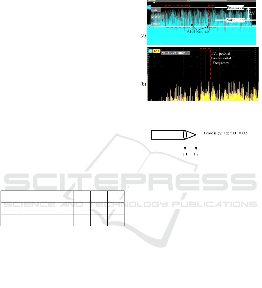
For more analytical analysis, an FFT has been
applied to the sensed signal to evaluate the gain (in
dBm) at the fundamental frequency of 16MHz, that is
equal to the clock frequency of the Arduino Mega, as
shown in the Figure 4. From the result in Table 3, it
is observed that for both NF-based and FFT
calculation, the G1 and P1 seems to show better
results. Although empirically NF-based solution
helps to observe signal analysis in the time domain,
the result for sensing a signal is more accurately be
considered in the frequency domain. The results from
Figure 4 and Table 3, suggests that coils G1 and P1
are suitable hybrid EM probe. But this is applicable
for the DUT used in this work. The results highly
depend upon DUT, test platform, algorithm etc.
Table 3: Results of emission for different probes.
Probes G1 G2 R1 R2 P1 P2
FFT
(dBm)
-4.51 -7.12 -6.02 -9.64 -6.66 -6.01
NF
(mV)
508.4 495.3 376.9 490.9 541.2 531.6
5.3 Figure-of-Merit
As seen from the above results, when using such a
hybrid-EM probe, a trade-off is needed to meet the
requirements for SCA and FIA. In this case, an
empirical formula has been proposed in (4):
=
1
1
+
1
2
(4)
where,
is magnetic permeability, N is no. turns,
D1 and D2 are diameters of the core refer Figure 5.
The expression obtained considers how the IPS and
the DPS values will correspond to the test
requirements (test_req).
The (D1/D2) factor has been added to consider
the shape of the tip. This suggests empirically that the
bigger the FM value is, the better the trade-off
between sensing and injecting capability is.
Figure 4: EM emission observed from hybrid probe. (a)
AES rounds with Noise Floor approach. (b) FFT of AES
emission.
Figure 5: A basic geometry of flathead and sharp-tip probe.
6 CONCLUSION
In this paper a thorough study has been conducted on
characteristics and parameters of EM coil. Using this
study, a novel hybrid nature of EM coil has been
designed, and subsequently a figure-of-merit is
proposed. The experiments conducted on FI and SCA
parts highlights that the designed hybrid coils can
sense and emit the EM signals to/from the DUTs. The
experimental results showcase that such designs can
enable a novel guidance-based EM-FI techniques,
significantly increasing the EM-FI effectiveness,
while reducing the attack model cost and complexity.
As a future effort, the EM probe setting will be
evaluated against lower nano-meter tech nodes.
REFERENCES
Abdellatif, K. M., & Heriveaux, O. (2020). SiliconToaster:
A Cheap and Programmable EM Injector for Extracting
Secrets. 2020 Workshop on Fault Detection and
Tolerance in Cryptography (FDTC), 35–40.
https://doi.org/10.1109/FDTC51366.2020.00012.
Barenghi, A., Breveglieri, L., Koren, I., & Naccache, D.
(2012). Fault Injection Attacks on Cryptographic
Devices: Theory, Practice, and Countermeasures.
EMplifier: Hybrid Electromagnetic Probe for Side Channel and Fault Injection Analysis
821

Proceedings of the IEEE, 100(11), 3056–3076.
https://doi.org/10.1109/JPROC.2012.2188769.
Beckers, A., Kinugawa, M., Hayashi, Y., Fujimoto, D.,
Balasch, J., Gierlichs, B., & Verbauwhede, I. (2020).
Design Considerations for EM Pulse Fault Injection
(pp. 176–192). https://doi.org/10.1007/978-3-030-
42068-0_11.
Caciagli, A., Baars, R. J., Philipse, A. P., & Kuipers, B. W.
M. (2018). Exact expression for the magnetic field of a
finite cylinder with arbitrary uniform magnetization.
Journal of Magnetism and Magnetic Materials, 456,
423–432. https://doi.org/10.1016/j.jmmm.2018.02.003
Chusseau, L., Omarouayache, R., Raoult, J., Jarrix, S.,
Maurine, P., Tobich, K., Bover, A., Vrignon, B.,
Shepherd, J., Le, T.-H., Berthier, M., Riviere, L.,
Robisson, B., & Ribotta, A.-L. (2014). Electromagnetic
analysis, deciphering and reverse engineering of
integrated circuits (E-MATA HARI). 2014 22nd
International Conference on Very Large Scale
Integration (VLSI-SoC), 1–6. https://doi.org/10.1109/
VLSI-SoC.2014.7004189.
Common Criteria. 2022. Common Methodology for
Information Technology Security Evaluation.
Dannehl, J., Liserre, M., & Fuchs, F. W. (2011). Filter-
Based Active Damping of Voltage Source Converters
With $LCL$ Filter. IEEE Transactions on Industrial
Electronics, 58(8), 3623–3633. https://doi.org/10.11
09/TIE.2010.2081952.
Dehbaoui, A., Dutertre, J.-M., Robisson, B., & Tria, A.
(2012). Electromagnetic Transient Faults Injection on a
Hardware and a Software Implementations of AES.
2012 Workshop on Fault Diagnosis and Tolerance in
Cryptography, 7–15.
https://doi.org/10.1109/FDTC.2012.15.
EM-FI Transient Probe Adjustable Pulse Width - Riscure.
(n.d.). Retrieved September 13, 2023, from
https://www.riscure.com/em-fi-transient-probe-apw/
Gaine, C., Nikolovski, J.-P., Aboulkassimi, D., & Dutertre,
J.-M. (2022). New Probe Design for Hardware
Characterization by ElectroMagnetic Fault Injection.
2022 International Symposium on Electromagnetic
Compatibility – EMC Europe, 299–304. https://doi.org/
10.1109/EMCEurope51680.2022.9901104.
Giri, D., King, R., & Wu, T. (n.d.). A theoretical and
experimental study of the ferrite rod antenna. 1977
Antennas and Propagation Society International
Symposium, 242–245. https://doi.org/10.1109/APS.197
7.1147716.
Kinsler, P. (2020). Faraday’s Law and Magnetic Induction:
Cause and Effect, Experiment and Theory. Physics, 2(2),
148–161. https://doi.org/10.3390/physics2020009.
Koeune, F., & Standaert, F.-X. (2005). A Tutorial on
Physical Security and Side-Channel Attacks (pp. 78–
108). https://doi.org/10.1007/11554578_3.
Li, H., Xing, J., & Ma, J. (2016). A high-assurance trust
model for digital community control system based on
internet of things. Wuhan University Journal of Natural
Sciences, 21(1), 29–36. https://doi.org/10.1007/s118
59-016-1135-z.
Mansour, S., & Lauf, A. (2020). Hardware Root Of Trust
for IoT Security In Smart Home Systems. 2020 IEEE
17th Annual Consumer Communications & Networking
Conference (CCNC), 1–2. https://doi.org/10.1109/CCN
C46108.2020.9045412.
NAE-CW520. (n.d.). Retrieved September 13, 2023, from
https://www.newae.com/products/NAE-CW520.
Nikitin, P., Rao, K. V. S., & Lazar, S. (2007). An Overview
of Near Field UHF RFID. 2007 IEEE International
Conference on RFID, 167–174. https://doi.org/10.11
09/RFID.2007.346165.
Oliveira, M. H., & Miranda, J. A. (2001). Biot-Savart-like
law in electrostatics. European Journal of Physics,
22(1), 31–38. https://doi.org/10.1088/0143-0807/22/1/
304.
Omarouayache, R., Raoult, J., Jarrix, S., Chusseau, L., &
Maurine, P. (2013). Magnetic microprobe design for
EM fault attack. 2013 International Symposium on
Electromagnetic Compatibility, 949–954.
Ordas, S., Guillaume-Sage, L., & Maurine, P. (2017).
Electromagnetic fault injection: the curse of flip-flops.
Journal of Cryptographic Engineering, 7(3), 183–197.
https://doi.org/10.1007/s13389-016-0128-3.
Trabelsi, O., Sauvage, L., & Danger, J.-L. (2019).
Characterization at Logical Level of Magnetic
Injection Probes. 625–628. https://doi.org/10.23919/
EMCTokyo.2019.8893692.
Zhu, W., Yin, W., Peyton, A., & Ploegaert, H. (2011).
Modelling and experimental study of an
electromagnetic sensor with an H-shaped ferrite core
used for monitoring the hot transformation of steel in an
industrial environment. NDT & E International, 44(7),
547–552. https://doi.org/10.1016/j.ndteint.2011.05.005.
ICISSP 2024 - 10th International Conference on Information Systems Security and Privacy
822
