
Cycle-Accurate Virtual Prototyping with Multiplicity
Daniela Genius
1
and Ludovic Apvrille
2
1
Sorbonne Université, LIP6, CNRS UMR 7606, Paris, France
2
LTCI, Télécom Paris, Institut Polytechnique de Paris, Paris, France
Keywords:
Virtual Prototyping, System-Level Design, Multiplicity, Design Space Exploration.
Abstract:
Model-based design for large applications, especially the mapping of applications’ tasks to execution nodes,
remains a challenge. In this paper, we explore applications comprising multiple identical software tasks in-
tended for deployment across diverse execution nodes. While these tasks are expected to have a unified repre-
sentation in their SysML-like block diagrams, each must be specifically mapped to individual processor cores
to achieve granular performance optimization. Additionally, inter-task communications should be allocated
across multiple channels. We further demonstrate a method for automatically generating parallel POSIX C
code suitable for a multiprocessor-on-chip. Our approach has proven especially effective for high-performance
streaming applications, notably when such applications have a master-worker task structure.
1 INTRODUCTION
As shown by (Burch et al., 2002), designing embed-
ded applications at different abstraction levels helps
verifying the correctness of the system. In this paper,
we design embedded application at a high abstraction
level, thus pushing forward hardware constraints to
modeling refinements. Many tools propose the pos-
sibility to express the multiplicity of tasks and chan-
nels, but lack the possibility to map them to multi-
processor platforms, with the idea of exploring di-
verse mapping alternatives (a.k.a. design space explo-
ration). Pushing the problem even further, task-farm
parallelism, that can be found in high performance
telecommunication and video streaming applications,
usually results in a huge number of tasks. Applica-
tions consist of alternating levels of producer and con-
sumer tasks, each consumer task waiting for data pro-
duced by any one of the producer tasks.
Our tool (Apvrille, 2023) offers a comprehensive
multi-level modeling and prototyping environment,
initiating from levels akin to SysML. The work in
(Li et al., 2018) extended its capabilities, facilitating
code generation down to the SystemC virtual proto-
type, which is constructed using cycle-accurate mod-
els of the hardware components. This enhancement
enables highly detailed simulations. Nonetheless, a
notable drawback is that every task must be explicitly
delineated in the block diagram, rendering the design
space exploration process to be somewhat tedious.
The paper defines a process to efficiently repre-
sent applications with numerous tasks and channels in
SysML block diagrams and subsequently the efficient
allocation of these tasks and channels to a specific
hardware platform. This hardware platform acts as
an input model, facilitating the generation of a cycle-
accurate virtual prototype. Such a prototype enables
precise simulations to determine optimal task deploy-
ment. Consequently, our extension paves the way for
a more comprehensive modeling of multi-task appli-
cations and their deployment on multi-core platforms.
After discussing related work in Section 2, we in-
troduce the underlying concepts (Model-based engi-
neering, applications with many tasks) in Section 3.
Our contribution is described in Section 4 with a toy
system, and applied to a larger case study in Section
5 before we conclude.
2 RELATED WORK
Many system-level design approaches exist, with
the majority permitting multiple application tasks
and their allocation to virtual prototypes of multi-
processor platforms. Few however propose several
levels of simulation, or even lower the simulation
level to be cycle precise.
The ARTEMIS (Pimentel et al., 2001) project
originates from heterogeneous platforms in the con-
text of research on multimedia applications in partic-
ular. Application and architecture are clearly sepa-
rated: the application produces an event trace at sim-
ulation time, which is then read in by the architec-
ture model. However, low-level behavior depending
Genius, D. and Apvrille, L.
Cycle-Accurate Virtual Prototyping with Multiplicity.
DOI: 10.5220/0012386100003645
In Proceedings of the 12th International Conference on Model-Based Software and Systems Engineering (MODELSWARD 2024), pages 187-194
ISBN: 978-989-758-682-8; ISSN: 2184-4348
Copyright © 2024 by Paper published under CC license (CC BY-NC-ND 4.0)
187

on timers and interrupts cannot be taken into account.
Sesame (Erbas et al., 2006) proposes modeling
and simulation features at several abstraction levels.
Pre-existing virtual components are combined to form
a complex hardware architecture. Models’ semantics
vary according to the levels of abstraction, ranging
from Kahn process networks (KPN (Kahn, 1974)) to
data flow for model refinement, and to discrete events
for simulation. Sesame models consider neither mem-
ory mapping nor the choice of the communication ar-
chitecture.
(Di Natale et al., 2014) proposes the generation
of communication managers for software low layers
of telecommunication applications. Yet, they do not
handle task-farm type applications, nor do they offer
formal verification.
(Batori et al., 2007) proposes a design methodol-
ogy specifically for task parallel telecommunication
applications, using several formalisms to capture the
application structure. Behavior is described as Fi-
nite State Machines, then a deployment is found from
which executable code can be generated. The plat-
form is limited by its specificity and no design explo-
ration seems possible; code generation targets a real
platform instead of a prototyping environment.
UML/SysML based modeling techniques are very
popular in embedded system design. MARTE (Vi-
dal et al., 2009) separates communications from the
pair application-architecture, but intrinsically lacks
separation between control aspects and message ex-
changes. Even if the UML profile for MARTE adds
capabilities to model Real Time and Embedded Sys-
tems, it does not specifically support architectural ex-
ploration. These approaches are however scarcely
used for low-level simulation. With very few excep-
tions such as (Taha et al., 2010), they do not support
full-system simulation. The work presented in (Revol
et al., 2008) supports generation of IP-XACT models.
3 BASIC CONCEPTS
3.1 Model-Based Engineering
Model-based engineering of embedded systems can
be performed at different abstraction levels, com-
monly grouped into two subsets: functional and par-
titioning (high level), software design and deploy-
ment (low level). Specific SysML views and diagrams
can be used for each abstraction level (e.g., block
diagrams, use of allocations). Software and hard-
ware tasks to be partitioned are first captured within
the functional abstraction level. Then, functions and
their communications are mapped to abstract hard-
ware components.
After partitioning, software tasks can be further
detailed and then deployed on more concrete hard-
ware components. Thus, software deployment in-
tends to experiment the interaction of software with
all other components (digital and analog).
3.2 Master-Worker Paradigm
In embedded systems, communications predomi-
nantly take a one-to-one scheme, with one-to-many
used for broadcast communications. In contrast,
high-performance streaming applications often fea-
ture many-to-many communications. Among various
parallel computing paradigms (Barney et al., 2010),
master-worker is particularly suitable for massively
parallel applications.
This pattern is especially prevalent in task farm
applications, where multiple producer tasks interact
with multiple consumer tasks. However, a notable
drawback is the need to model each task individually,
which becomes cumbersome when modeling a large
number of tasks with identical functionalities.
3.3 NUMA Architectures
Non Uniform Memory Access (NUMA) is a design
scheme for massively parallel hardware designs, such
as the ones used for high performance streaming ap-
plications. Memories are separated and placed at dif-
ferent locations: this splitting of memories leads to
different access times to memories and may lead to
access conflicts as well, particularly in MP-SoC based
on clustered on-chip interconnects. Latency and con-
flicts lead to possible extra waiting time for new data
reaching the system and to buffer overflows. In such
NUMA systems, the correct mapping of tasks to pro-
cessors is therefore challenging, especially when a
huge number of tasks is considered.
3.4 Method
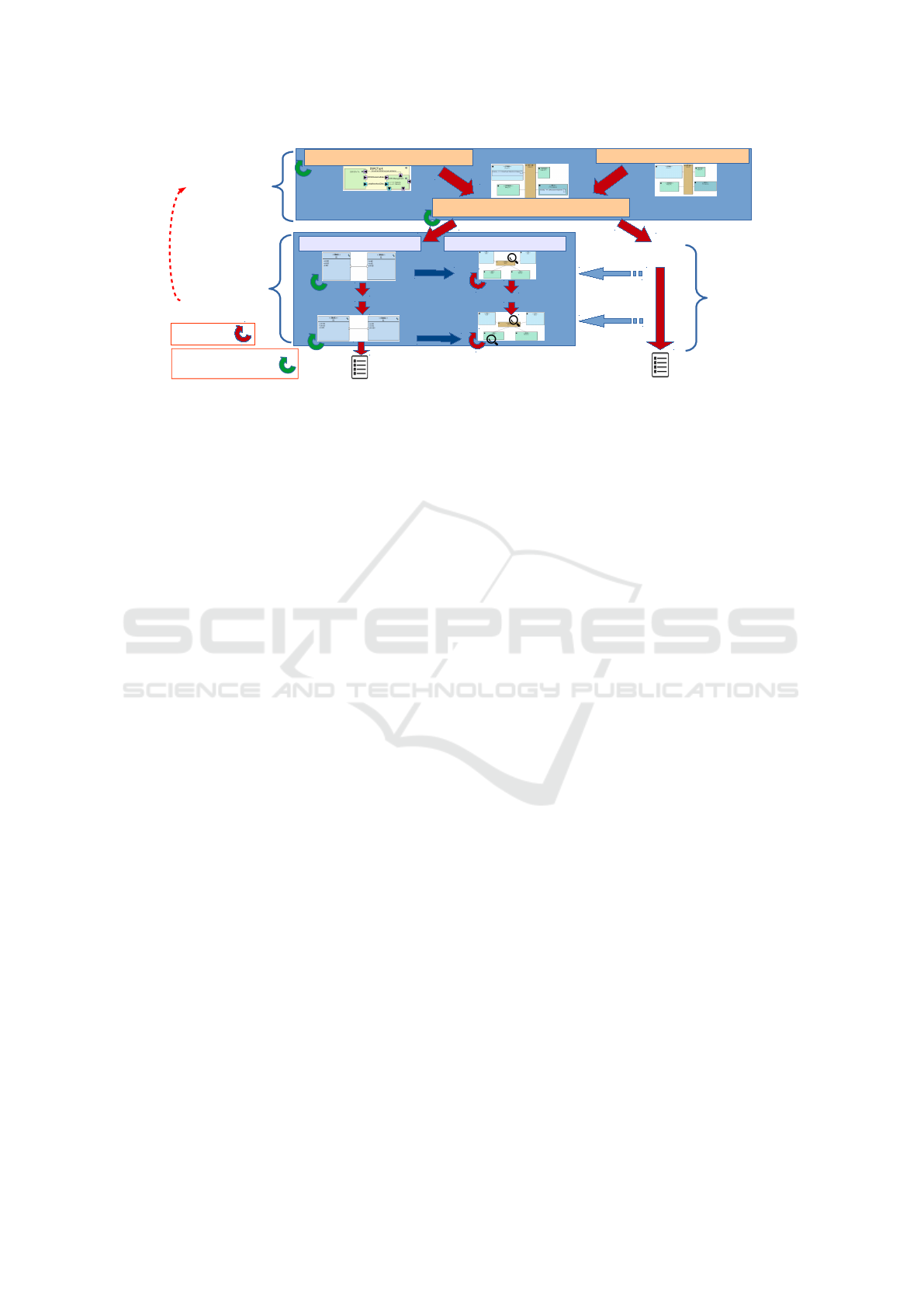
Figure 1 shows the overall method on which our con-
tribution relies. This Figure features the different
modeling phases of the design process, and the evalu-
ation of the different models with simulation and for-
mal verification.
On the partitioning level, functionality is de-
scribed with SysML-like diagrams, and a C++ simu-
lation from partitioning model helps taking allocation
decisions. On software design level, formal verifica-
tion intends to evaluate safety and security properties,
MODELSWARD 2024 - 12th International Conference on Model-Based Software and Systems Engineering
188
Final software code
Refinements
VHDL/Verilog
2. Software
Design and
Prototyping
(AVATAR)
Deployment view
...
...
Hardware
design
Abstractions
Abstractions
Reconsideration
of partitioning
decisions
Simulation
Formal verification
and simulation
Mapping view
Functional view
Architecture view
Software Component
Hardware
model
1. Partitioning
with
Design Space
Exploration
techniques
(DIPLODOCUS)
Figure 1: Methodology (from (Li et al., 2018)).
and a virtual prototype can then be generated for more
refined performance evaluation.
Our improved method relies on a set of UM-
L/SysML views supported within the same toolkit,
TTool (Apvrille, 2023). The method is as follows:
1. Hardware/software partitioning based on design
space exploration techniques contains three sub-
phases: modeling of the functions to be real-
ized by the system ("functional view"), model-
ing of the candidate architecture ("architecture
view"), and mapping ("mapping view"). A func-
tion mapped onto a processor is thus implemented
as a software function, a function mapped onto
a hardware accelerator corresponds to a custom
Application Specific Integrated Circuit (ASIC).
At this stage, we are mostly concerned with how
communications and function affect the perfor-
mance of a mapping. Logical communication be-
tween functions are mapped on a "communication
path" consisting of buses, bridges, memories, etc.
2. Once the system is fully partitioned, the software
and the hardware are designed using the AVATAR
environment (Pedroza et al., 2011). This approach
offers software modeling while taking into ac-
count hardware parameters. A software compo-
nent view is used to build the system software ar-
chitecture and behavior, a deployment view shows
how software components are mapped to the hard-
ware components. The model of software and
hardware components is progressively refined,
the most refined model serves to generate a vir-
tual prototype consisting of hardware models de-
scribed in SystemC and software in the form of C
POSIX tasks.
3.5 Simulation, Verification and
Prototyping
The toolkit offers a press-button approach for per-
forming safety and security proofs by simulation and
formal verification. It also checks if performance re-
quirements are met. Model transformations translate
the SysML models into an intermediate form that is
sent to the underlying simulation and formal verifica-
tion toolkits - some of them third party.
While during functional modeling, not considered
in this paper, formal verification aims at identifying
general safety properties (e.g., absence of deadlock
situations), in the software design and mapping phase,
verification intends to check if performance and secu-
rity requirements are met. Hardware components are
still abstracted, e.g., a CPU is defined with a set of
parameters such as cache-miss ratio, context switch
penalty, etc.
When the software components are more refined,
it becomes important to evaluate performance. Since
the target system is commonly not yet available, our
approach offers a deployment view in which software
components can be mapped onto hardware nodes, and
a press-button approach to transform the deployment
diagram into a specification built upon virtual com-
ponent models using a free SystemC library called
SoCLib (SoCLib consortium, 2016). SoCLib is a
public domain library of models written in SystemC,
targeting shared-memory architectures. SoCLib con-
tains a set of performance evaluation tools for level
simulation which allow to measure cache miss rate,
latency of memory accesses and the fill state of the
buffers, taking/releasing of locks etc. on a cycle-
precise level. Note that on this level, the approaches
is purely based on simulating on the virtual prototype
and it is no more possible to formally verify, due to
high complexity and level of detail.
The method described in (Li et al., 2018) and
Cycle-Accurate Virtual Prototyping with Multiplicity
189
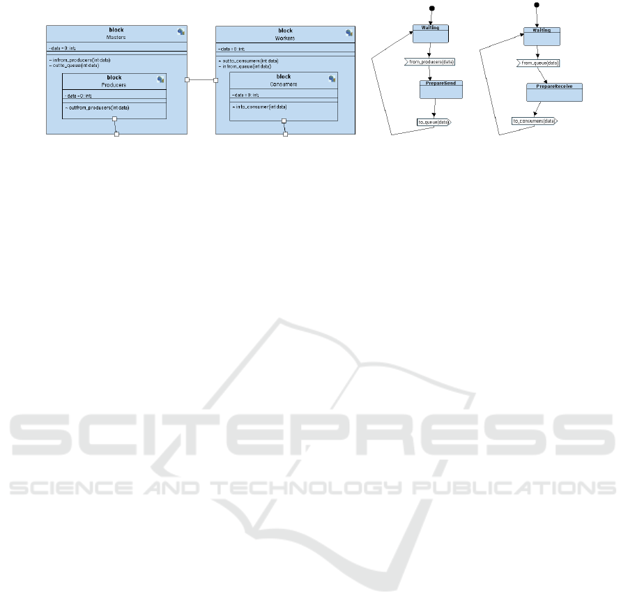
Figure 2: Masters and Workers block diagram (left) and state machines (right) using multiplicity.
shown in Figure 1 implies that if these performance
results differ too much from the results obtained dur-
ing the design space exploration stage, the design
space exploration must be performed again Once the
iterations over the high-level design space exploration
and the low level virtual prototyping of software com-
ponents finished, software code can be generated
from the most refined software model.
4 CONTRIBUTION
The present paper proposes an extension of the high-
level modeling capabilities of TTool (Apvrille et al.,
2006) with multiple parallel tasks. For this, we need
to extend the notion of the SysML Block Diagram to
represent multiple, identical blocks.
4.1 Modeling
From a SysML point of view, block definition and in-
ternal block diagrams are used to capture functions
and architectural components. An additional param-
eter now allows to define the number of identical in-
stances. Blocks that are thus replicated share the same
definition and behavior. In the example of Figure 2 we
have identical instances of the Producers sub task.
When the origin or destination task of a channel
is replicated, the channel has to be replicated too, or
one channel is shared between several origin or sev-
eral destination tasks, or any combination depending
on the task and channels allocation and replication
scheme selected by the user. Here, we choose to repli-
cate the channel to correspond to the number of tasks.
Alternatively, one channel could be shared between
all tasks, or any combination of groups of tasks read-
ing from/writing to a common channel.
This new freedom has consequences on the state
machine diagrams. Identical tasks communicating
through identical channels share the same state ma-
chine diagram. Their channels will be considered
to be multicast channels. For all other replication
schemes, we currently propose one state machine per
block.
4.2 Mapping
Using a deployment diagram where tasks and chan-
nels are allocated to processors and memory, respec-
tively, our tool is capable of generating a parallel
hardware platform suitable for virtual prototyping.
Tasks allocated to a processor are implemented in
software, while those designated to a hardware accel-
erator or FPGA in hardware. Several tasks can share a
node in CPUs or FPGAs, whereas a hardware acceler-
ator can accommodate only a single task. Simulating
these mapping models provides valuable insights into
system performance.
Functional channels must be mapped as well.
When their origin or destination task is replicated,
they must be replicated too, or shared between the
tasks, or any combination depending on the task and
channels allocation and replication scheme selected
by the user.
Blocks (called block artifacts in the deployment
view) are mapped onto CPUs using a pull-down
menu. Identical blocks are not automatically mapped
to the same processor, a design decision which ac-
cepts by doing so that mapping of dozens of blocks
individually is a little cumbersome. Still, it requires
only a few mouse clicks.
Now, we can express the master-worker paradigm
defined in Section 3.2 in a compact way, see Figure 2.
Note that multiplicity can be parameterized by modi-
fying one parameter in the block diagram.
4.3 Code Generation and Virtual
Prototype
Multicast channels are naturally translated into the
Multiple Writer/Multiple Reader (MWMR) channels
of SoCLib. Mapped to memory, they have a com-
plex access scheme (Genius et al., 2011), but corre-
spond best to the master/worker paradigm where ev-
ery master deposes work to a common channel, which
is fetched by any worker, without an order to be re-
MODELSWARD 2024 - 12th International Conference on Model-Based Software and Systems Engineering
190
block
Scheduling
- packet : PacketDesc;
~ in from_queue_low(PacketDesc packet)
~ in from_queue_medium(PacketDesc packet)
~ in from_queue_high(PacketDesc packet)
~ out to_scheduler0(PacketDesc packet)
~ out to_scheduler1(PacketDesc packet)
~ in scheduledPacket0(PacketDesc packet)
~ in scheduledPacket1(PacketDesc packet)
block
Sched0
- packet : PacketDesc;
~ out scheduledPacket0(PacketDesc packet)
~ in toScheduler0(PacketDesc packet)
block
Sched1
- packet : PacketDesc;
~ out scheduledPacket1(PacketDesc packet)
~ in toScheduler1(PacketDesc packet)
block
Classification
- packet : PacketDesc;
- f1 = true : bool;
- f0 = true : bool;
- f2 = true : bool;
~ out queue_low(PacketDesc packet)
~ out queue_medium(PacketDesc packet)
~ out queue_high(PacketDesc packet)
~ in c0_to_queue_low(PacketDesc packet)
~ in c1_to_queue_low(PacketDesc packet)
~ in c2_to_queue_low(PacketDesc packet)
~ in c0_to_queue_medium(PacketDesc packet)
~ in c1_to_queue_medium(PacketDesc packet)
~ in c2_to_queue_medium(PacketDesc packet)
~ in c0_to_queue_high(PacketDesc packet)
~ in c1_to_queue_high(PacketDesc packet)
~ in c2_to_queue_high(PacketDesc packet)
~ out to_c0(PacketDesc packet)
~ out to_c1(PacketDesc packet)
~ out to_c2(PacketDesc packet)
block
Classif2
- packet : PacketDesc;
~ out to_queue_low(PacketDesc packet)
~ out to_queue_medium(PacketDesc packet)
~ out to_queue_high(PacketDesc packet)
~ in from_classif(PacketDesc packet)
block
Classif1
- packet : PacketDesc;
~ out to_queue_low(PacketDesc packet)
~ out to_queue_medium(PacketDesc packet)
~ out to_queue_high(PacketDesc packet)
~ in from_classif(PacketDesc packet)
block
Classif0
- packet : PacketDesc;
- nbPackets : int;
~ out to_queue_low(PacketDesc packet)
~ out to_queue_medium(PacketDesc packet)
~ out to_queue_high(PacketDesc packet)
~ in from_classif(PacketDesc packet)
<<datatype>>
PacketDesc
- address : int;
- date : int;
block
Scheduling
- packet : PacketDesc;
~ in from_queue_low(PacketDesc packet)
~ in from_queue_medium(PacketDesc packet)
~ in from_queue_high(PacketDesc packet)
~ out to_scheduler0(PacketDesc packet)
~ out to_scheduler1(PacketDesc packet)
~ in scheduledPacket0(PacketDesc packet)
~ in scheduledPacket1(PacketDesc packet)
block
Sched0
- packet : PacketDesc;
~ out scheduledPacket0(PacketDesc packet)
~ in toScheduler0(PacketDesc packet)
block
Sched1
- packet : PacketDesc;
~ out scheduledPacket1(PacketDesc packet)
~ in toScheduler1(PacketDesc packet)
block
Classification
- packet : PacketDesc;
- f1 = true : bool;
- f0 = true : bool;
- f2 = true : bool;
~ out queue_low(PacketDesc packet)
~ out queue_medium(PacketDesc packet)
~ out queue_high(PacketDesc packet)
~ in c0_to_queue_low(PacketDesc packet)
~ in c1_to_queue_low(PacketDesc packet)
~ in c2_to_queue_low(PacketDesc packet)
~ in c0_to_queue_medium(PacketDesc packet)
~ in c1_to_queue_medium(PacketDesc packet)
~ in c2_to_queue_medium(PacketDesc packet)
~ in c0_to_queue_high(PacketDesc packet)
~ in c1_to_queue_high(PacketDesc packet)
~ in c2_to_queue_high(PacketDesc packet)
~ out to_c0(PacketDesc packet)
~ out to_c1(PacketDesc packet)
~ out to_c2(PacketDesc packet)
block
Classif2
- packet : PacketDesc;
~ out to_queue_low(PacketDesc packet)
~ out to_queue_medium(PacketDesc packet)
~ out to_queue_high(PacketDesc packet)
~ in from_classif(PacketDesc packet)
block
Classif1
- packet : PacketDesc;
~ out to_queue_low(PacketDesc packet)
~ out to_queue_medium(PacketDesc packet)
~ out to_queue_high(PacketDesc packet)
~ in from_classif(PacketDesc packet)
block
Classif0
- packet : PacketDesc;
- nbPackets : int;
~ out to_queue_low(PacketDesc packet)
~ out to_queue_medium(PacketDesc packet)
~ out to_queue_high(PacketDesc packet)
~ in from_classif(PacketDesc packet)
<<datatype>>
PacketDesc
- address : int;
- date : int;
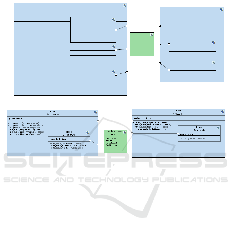
Figure 3: Block diagram of the classification application without multiplicity.
Figure 4: Block Diagram of the classification application featuring multiple blocks and channels.
spected except FIFO. Generated code will be run on
the SoCLib platform under a micro kernel, C POSIX
threads being created for each of the tasks.
5 CASE STUDY
The following case study illustrates the additional
features we propose for handling applications with
many similar tasks. Note that it is not limited, but
most relevant, to task-farm type parallel applications.
A telecommunication application modeled in SysML
in (Genius et al., 2019) serves as case study; it could
initially only handle a fixed number of tasks for both
the classifier and the scheduler stages.
All tasks of a stage n can read the data output by
all tasks of stage n − 1. Basically, the application first
cuts network packets into chunks of equal size car-
rying descriptors referencing the address of the next
chunk. A packet chunk contains a 32-bit address, then
11 bits for the TotalSize, then 20 bits date for a time
stamp, and finally an internal boolean indicating if
the packet is stored on-chip or off-chip, for a total of
64 bits. Only descriptors are sent through the chan-
nels: indeed, packet data are kept in on-chip or off-
chip memories while being routed. For the sake of
simplicity, I/O co-processors are not modeled. Thus,
tasks part of the current case study are:
• The Classification tasks read one or several de-
scriptors at a time, then retrieve the first chunk of
the corresponding packet from memory. Any clas-
sification task can access any chunk. Inner classi-
fier tasks determine the priority of each packet.
• The Scheduling tasks read one of the priority
queues according to their order, then write de-
scriptor to an output. The inner scheduler tasks
schedule the packet, based on its priority.
In order to maximize performance, both classification
and scheduling tasks use try-read primitives to start
work whenever data is available. We do not consider
I/O and bootstrap tasks in this case study.
5.1 Block Diagram
Figure 3 shows the simplified AVATAR block dia-
gram of the original telecommunication application,
without the I/O mechanisms. This software architec-
ture shows refined elements such as the data structure
PacketDesc defined as a data type which is exchanged
Cycle-Accurate Virtual Prototyping with Multiplicity
191
Classif_multi/out to_queue_low
Classif_multi/out to_queue_high
AVATAR Design::Block0AVATAR Design::Classif_multiAVATAR Design::Block0AVATAR Design::Classif_multiAVATAR Design::Block0AVATAR Design::Classif_multiAVATAR Design::Block0AVATAR Design::Scheduling
<<CPU>>
CPU1
<<CPU>>
CPU3
<<CPU>>
CPU0
<<TTY>>
TTY0
<<VGMN>>
ICN0
<<CPU>>
CPU2
<<RAM>>
Memory0
Classif_multi/out to_queue_low
<<CPU>>
CPU4
AVATAR Design::Block0
<<CROSSBAR>>
Crossbar2
<<CROSSBAR>>
Crossbar0
<<CROSSBAR>>
Crossbar1
<<CROSSBAR>>
Crossbar3
<<CPU>>
CPU5
<<CPU>>
CPU6
<<CPU>>
CPU7
AVATAR Design::Block0
<<CPU>>
CPU1
<<CPU>>
CPU3
<<CPU>>
CPU0
<<TTY>>
TTY0
<<VGMN>>
ICN0
<<CPU>>
CPU2
<<RAM>>
Memory0
Classif_multi/out to_queue_low
<<CPU>>
CPU4
<<CROSSBAR>>
Crossbar2
<<CROSSBAR>>
Crossbar0
<<CROSSBAR>>
Crossbar1
<<CROSSBAR>>
Crossbar3
<<CPU>>
CPU5
<<CPU>>
CPU6
<<CPU>>
CPU7
AVATAR Design::Block0AVATAR Design::Classif_multi
AVATAR Design::Block0AVATAR Design::Classif_multi
AVATAR Design::Block0AVATAR Design::Classif_multi
AVATAR Design::Block0AVATAR Design::Classif_multi
AVATAR Design::Block0AVATAR Design::Classif_multi
AVATAR Design::Block0AVATAR Design::Classif_multi
AVATAR Design::Block0AVATAR Design::Classif_multiAVATAR Design::Block0AVATAR Design::Classif_multiAVATAR Design::Block0AVATAR Design::Classif_multiAVATAR Design::Block0AVATAR Design::Sched_multi
AVATAR Design::Block0AVATAR Design::Classif_multiAVATAR Design::Block0AVATAR Design::Classif_multiAVATAR Design::Block0AVATAR Design::Classif_multiAVATAR Design::Block0AVATAR Design::Sched_multi
AVATAR Design::Block0AVATAR Design::Classif_multiAVATAR Design::Block0AVATAR Design::Classif_multiAVATAR Design::Block0AVATAR Design::Classif_multiAVATAR Design::Block0
AVATAR Design::Scheduler
Classif_multi/out to_queue_low
Classif_multi/out to_queue_medium
Classif_multi/out to_queue_low
Scheduler/in from_queue_low
Classif_multi/out to_queue_low
Scheduler/in from_queue_medium
Classif_multi/out to_queue_low
Scheduler/in from_queue_high
Classif_multi/out to_queue_low
Classif_multi/out to_queue_low
Classification/out queue_low
Classification/out queue_low
Classification/out queue_low
Classification/out queue_high
Classification/out queue_low
Classification/out queue_meduim
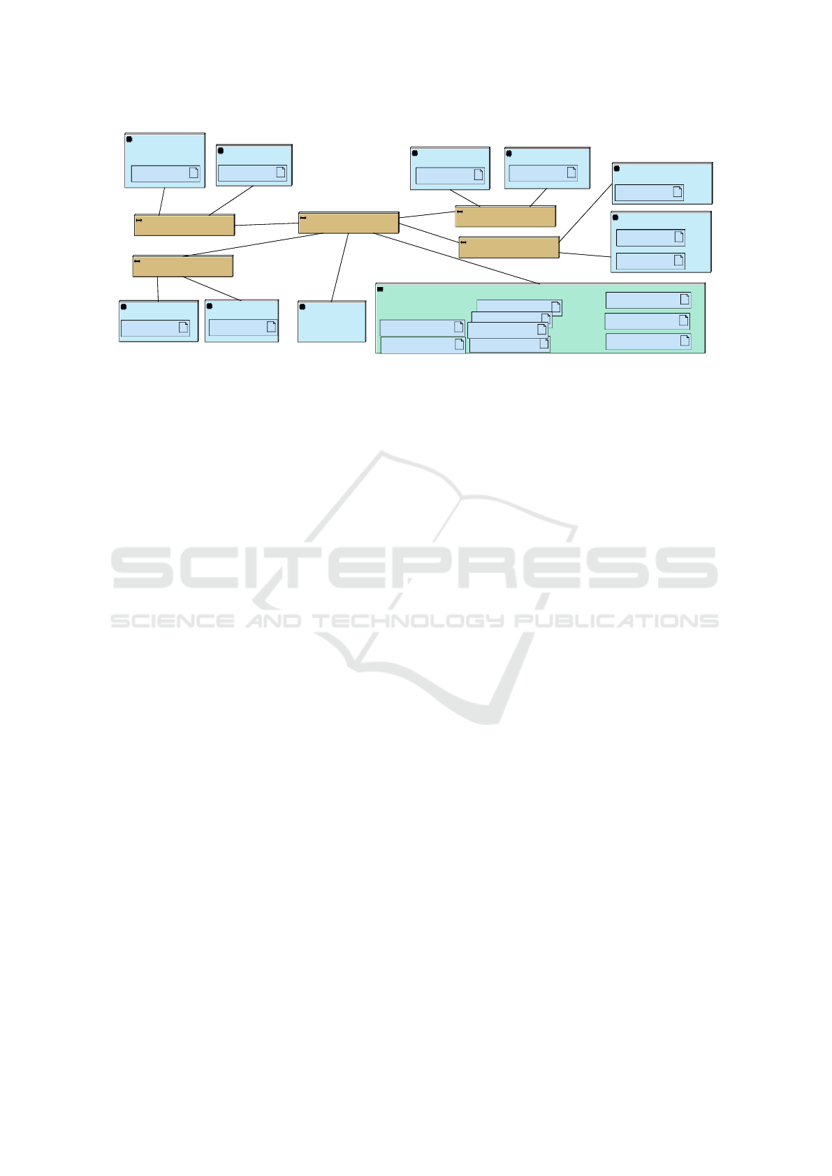
Figure 5: Deployment Diagram for the telecommunication application (6 classification, 2 scheduling tasks).
via channels. The software application model features
three classification tasks and two scheduling tasks and
has to be rewritten, including the state machines, ev-
ery time more tasks are to be added. The relatively
low number of tasks was due to former limitations
of the graphical SysML-like representation: diagrams
could not yet express replication of identical tasks
(i.e., multiplicity) and all diagrams and state machines
had to be designed manually for replication.
The main communication channel is defined be-
tween Classification and Scheduling. It conveys three
signals that correspond to the three priority queues.
Each priority queue (high, medium, low) is meant
to be transformed into a separate multi-writer multi-
reader channel in the SoCLib-based virtual platform.
The priority queues are modeled as asynchronous
channels, with a depth of 1024 descriptors.
Figure 4 shows the rewritten version of the ap-
plication, now featuring multiple blocks. Task-farm
parallelism can be conveniently captured using non-
deterministic choice in the state machines (not shown
for lack of space). The scheduling task which takes
as input available data in the priority queues are mod-
eled in a similar way. An outer task coordinates the
reading from the priority queues and the writing to the
output channel.
5.2 Mapping
The application is deployed on a clustered platform.
The generated virtual prototype supports a highly re-
alistic model of NUMA architectures as explained in
section 3.3; non-uniform memory acces effects such
as increased latency due to competition for the inter-
connect, and buffer overflow caused by a large num-
ber of tasks writing to the same multi-writer channel
without sufficient reads are acerbated by an increas-
ing number of tasks (up to eighty classification tasks
were employed in a study shown in (Genius et al.,
2011)). The AVATAR deployment diagram in Figure
5 illustrates one possible task and channel mapping
on a clustered NUMA platform.
5.3 Experimental Results
The two critical parameters that warrant exploration
for telecommunication and general streaming applica-
tions are latency and channel fill state. Latency refers
to the duration, measured in simulation cycles, that a
packet descriptor requires to complete an end-to-end
traversal. Channel fill state, on the other hand, per-
tains to the quantity of packet descriptors populating
the priority queues within a specified time interval.
5.3.1 Latencies
It is well known that low memory access latencies are
of critical importance for fast packet routing. How-
ever, clustered multiprocessor platforms, often used
to run these applications, usually suffer a high stan-
dard deviation for these latencies with regards to more
common platforms (Nikolov et al., 2008). Channels
are stored in memory, and the communications via
these channels represent a high fraction of the appli-
cation activity as shown in an initial C implementa-
tion (Genius et al., 2011). The higher the number of
tasks accessing a channel, the higher the amount of
time spent waiting for the lock in order to access con-
cerned the memory bank.
Figure 7.(a) shows the mean latencies, assuming
three priority queues (high, medium, low) and a ra-
tio of 3 to 1 (rounded downwards) between classifi-
cation and scheduler tasks. Results are still only par-
tially comparable to the implementation in C, as we
did not model packet memory accesses and I/O, but
in contrast to former work we can now vary the num-
ber of tasks by simple change of a parameter. In the
MODELSWARD 2024 - 12th International Conference on Model-Based Software and Systems Engineering
192
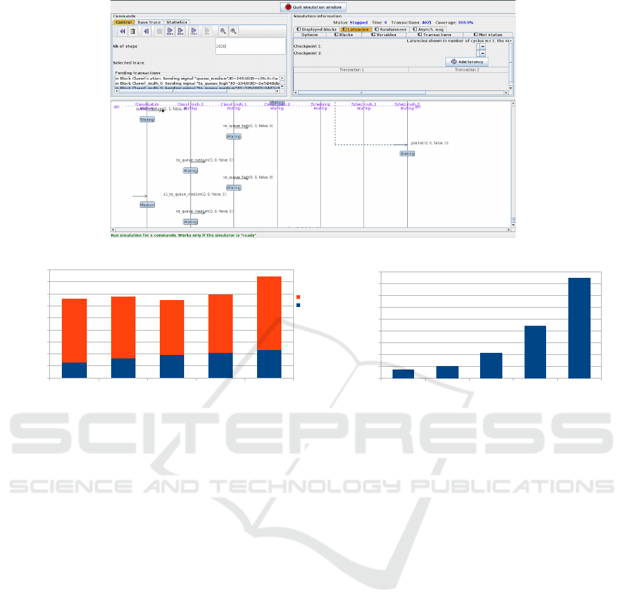
Figure 6: Interactive simulation on software design level.
20 40 60 80 100 tasks
0
100
200
300
400
500
600
700
800
900
transfer data
obtain lock
simulation cycles
(a)
20 40 60 80 100 tasks
0
20
40
60
80
100
120
140
160
180
Bytes
(b)
Figure 7: Mean latency (a) and fill state (b) per channel for 3 priority queues and a varying number of classification tasks.
first SysML version (Genius et al., 2019), only one
instance featuring three classification tasks and two
scheduling tasks was modeled.
5.3.2 Throughput
We keep track of the channel fill state using a Python
script and the SoCLib VCI logger. In our example, we
do not fix an input frequency; addresses are read as
soon as they are available and we assume that chan-
nels are never full: the channels were setup to hold
128 descriptors (1024 bytes). Figure 7.(b) shows the
mean fill state of the channels representing the prior-
ity queues, again for three priority queues and a ratio
of 3 to 1 (rounded downwards) between classification
and scheduler tasks. Figure 6 shows an extract of an
interactive simulation of C Posix code on software de-
sign level, referring to the determination of latencies.
5.3.3 Design Space Exploration
The application is now easily scalable by simple mod-
ification in the multiplicity menu. At the price of
placing tasks individually on processors in the De-
ployment Diagram, more fine-tuning becomes pos-
sible. As in the original C code version of (Genius
et al., 2011), which uses the same virtual platform
SoCLib groups of classification and scheduling tasks,
connected by groups of channels, can be mapped to-
gether on a cluster, in order to fine-tune performance.
6 DISCUSSION AND FUTURE
WORK
By representing multiple identical tasks, and allow-
ing multiplicity of channels, we significantly facili-
tate the design space exploration for task farm type
applications. The generated virtual prototype is very
detailed, making it particularly well adapted for fine
grain performance analysis and tuning.
It should be noted that the extension is useful
for the larger class of applications featuring multiple
identical tasks running in parallel, but only task farm
type applications fully exploit the potential of multi
writer multi reader channels.
Requiring individual state machines for multiple
blocks unless connected by channel replicated in the
same way is still time-consuming. It would be use-
ful to develop communications schemes similar to the
Psi-Chart (Enrici et al., 2017) for the functional level.
Cycle-accurate models are precise, but slow to
simulate – minutes to hours, depending on the number
Cycle-Accurate Virtual Prototyping with Multiplicity
193

of tasks and processors. We are currently working on
the integration of transaction-level and Qemu-based
virtual platforms.
REFERENCES
Apvrille, L. ((accessed 2023)). TTool, an open-source
toolkit for the modeling and verification of embedded
systems, https://ttool.telecom-paris.fr.
Apvrille, L., Muhammad, W., Ameur-Boulifa, R., Coudert,
S., and Pacalet, R. (2006). A UML-based environment
for system design space exploration. In 13th IEEE
Int. Conference on Electronics, Circuits and Systems,
pages 1272–1275.
Barney, B. et al. (2010). Introduction to parallel computing.
Lawrence Livermore National Laboratory, 6(13):10.
Batori, G., Theisz, Z., and Asztalos, D. (2007). Do-
main specific modeling methodology for reconfig-
urable networked systems. In Engels, G., Opdyke, B.,
Schmidt, D. C., and Weil, F., editors, MODELS’07,
pages 316–330. Springer.
Burch, J., Passerone, R., and Sangiovanni-Vincentelli, A.
(2002). Using multiple levels of abstractions in em-
bedded software design. In International Workshop
on Embedded Software, volume 2211.
Di Natale, M., Chirico, F., Sindico, A., and Sangiovanni-
Vincentelli, A. (2014). An MDA approach for the
generation of communication adapters integrating SW
and FW components from simulink. In MODELS’14,
pages 353–369.
Enrici, A., Apvrille, L., and Pacalet, R. (2017). A model-
driven engineering methodology to design parallel and
distributed embedded systems. ACM Trans. Des. Au-
tom. Electron. Syst., 22(2):34:1–34:25.
Erbas, C., Cerav-Erbas, S., and Pimentel, A. D. (2006).
Multiobjective optimization and evolutionary algo-
rithms for the application mapping problem in multi-
processor system-on-chip design. IEEE Evol. Comp.,
10(3):358–374.
Genius, D., Apvrille, L., and Li, L. W. (2019). High-level
modeling of communication-centric applications: Ex-
tensions to a system-level design and virtual prototyp-
ing tool. Microprocessors and Microsystems, 67:117–
130.
Genius, D., Faure, E., and Pouillon, N. (2011). Mapping
a telecommunication application on a multiprocessor
system-on-chip. In Gogniat, G., Milojevic, D., and
Erdogan, A. M. A. A., editors, Algorithm-Architecture
Matching for Signal and Image Processing, chapter 1,
pages 53–77. Springer LNEE vol. 73.
Kahn, G. (1974). The semantics of a simple language for
parallel programming. In Rosenfeld, J. L., editor, In-
formation Processing ’74: IFIP Congress, pages 471–
475. North-Holland, NY.
Li, L. W., Genius, D., and Apvrille, L. (2018). Formal and
virtual multi-level design space exploration. In MOD-
ELSWARD, Springer CCIS vol 880, pages 47–71.
Nikolov, H., Stefanov, T., and Deprettere, E. F. (2008). Sys-
tematic and automated multiprocessor system design,
programming, and implementation. IEEE Trans. on
CAD of Integrated Circuits and Systems, 27(3):542–
555.
Pedroza, G., Knorreck, D., and Apvrille, L. (2011).
AVATAR: A SysML environment for the formal veri-
fication of safety and security properties. In NOTERE,
Paris, France.
Pimentel, A. D., Hertzberger, L. O., Lieverse, P., van der
Wolf, P., and Deprettere, E. F. (2001). Exploring
embedded-systems architectures with artemis. IEEE
Computer, 34(11):57–63.
Revol, S., Taha, S., Terrier, F., Clouard, A., Gerard, S., Ra-
dermacher, A., and Dekeyser, J.-L. (2008). Unifying
hw analysis and soc design flows by bridging two key
standards: Uml and ip-xact. In IFIP Working Confer-
ence on Distributed and Parallel Embedded Systems,
pages 69–78. Springer.
SoCLib consortium (2016). SoCLib: an open platform for
virtual prototyping of multi-processors system on chip
(webpage). In http://www.soclib.fr.
Taha, S., Radermacher, A., and Gérard, S. (2010). An
entirely model-based framework for hardware design
and simulation. In Distributed, Parallel and Biologi-
cally Inspired Systems - 7th IFIP TC 10 Working Con-
ference, volume 329, pages 31–42. Springer.
Vidal, J., de Lamotte, F., Gogniat, G., Soulard, P., and
Diguet, J.-P. (2009). A co-design approach for embed-
ded system modeling and code generation with UML
and MARTE. In DATE’09, pages 226–231.
MODELSWARD 2024 - 12th International Conference on Model-Based Software and Systems Engineering
194
