
Efficiency of 3D Fractal Generation Through Raymarching
Anna Semrau
a
and Dariusz Sawicki
b
Warsaw University of Technology, Warsaw, Poland
Keywords: Fractals, Raymarching, Signed Distance Functions, Ray Tracing.
Abstract: The use of fractal geometry in computer graphics enables the modeling of natural objects which mathematical
description using traditional Euclidean geometry is difficult. However, fractals, due to their properties and
specific description, create application problems, especially related to computational and memory efficiency.
There are known attempts to solve these problems using graphic hardware and special algorithms. One of the
methods that could bring good results is the quite old and rarely used algorithm of raymarching with SDF
(Signed Distance Functions). The aim of the article is to analyze the possibility of using this method to
increase the efficiency of fractal modeling. Demonstration application that allows testing various modeling
cases has been developed, also taking into account the hardware of modern graphics cards. Research was
carried out for 5 different types of fractals (Sierpinski pyramid, Menger sponge, Julia set, Mandelbulb object,
fractal tree). The fractal image generation time and memory consumption were considered. For the Menger
sponge, different model generation methods were also compared: traditional boundary generation and those
using raymarching with SDF. The conducted research has shown that raymarching is a method worth
considering. Moreover, the application of raymarching with SDF can bring many measurable benefits.
1 INTRODUCTION
1.1 Motivation
Modern computer graphics often aim to provide a
realistic or even hyperrealistic representation of
reality. In the case of computer games or films, the
world created is supposed to provide the recipient
with the impression of strong immersion - to be
sufficiently convincing in its impact so that the
viewer or player feels a part of it as much as possible
(Slater, 2003, Berkman and Akan, 2019). This is a
challenge both for programmers, artists and designers
of broadly understood digital art, as well as for the
equipment that must meet the requirements. The
appearance of fractal geometry has revolutionized the
approach to modeling objects in computer graphics.
This made it possible to imitate elements of nature,
natural objects or other components of the real world,
where a mathematical description using traditional
Euclidean geometry is difficult or even impossible.
Benoit B. Mandelbrodt, the originator of fractal
modeling and the term "fractal" itself, points out the
a
https://orcid.org/0009-0001-0410-3248
b
https://orcid.org/0000-0003-3990-0121
problem of describing the irregularities of the real
world in the introduction to his book "The Fractal
Geometry of Nature" (Mandelbrodt, 1992).
According to him, nature, in order to be described,
requires an additional, completely different level of
complexity than that known before the appearance of
fractal geometry (Mandelbrodt, 1992). At the same
time, the complexity and diversity of natural objects
in the world around us make it impossible to create a
unified and universal fractal description (Peitgen et
al., 2013, Barnsley, 2012). The most commonly used
methods are: L-system (Lindenmayer system)
(Prusinkiewicz and Lindenmayer, 1996) and IFS
(Iterated Function System) (Barnsley, 2012).
The combination of modeling based on fractal
geometry with realistic graphics methods creates
application problems. The problem is not only the
effectiveness of the description of a real and complex
natural object, but above all the computational
efficiency of implementing such a task. There are
visible benefits of using fractal objects as models in
simulations, computer games and films. However,
despite the rapid development of the equipment used,
a compromise is still necessary between the quality of
252
Semrau, A. and Sawicki, D.
Efficiency of 3D Fractal Generation Through Raymarching.
DOI: 10.5220/0012380500003660
Paper published under CC license (CC BY-NC-ND 4.0)
In Proceedings of the 19th International Joint Conference on Computer Vision, Imaging and Computer Graphics Theory and Applications (VISIGRAPP 2024) - Volume 1: GRAPP, HUCAPP
and IVAPP, pages 252-260
ISBN: 978-989-758-679-8; ISSN: 2184-4321
Proceedings Copyright © 2024 by SCITEPRESS – Science and Technology Publications, Lda.

created graphics and the speed of calculations. Hence
the need to look for methods of effectively using
hardware to implement graphic applications in fractal
modeling.
1.2 The Aim of the Article
Ray tracing (RT) is one of the basic methods of
realistic graphics. The need for real-time
implementation results in a growing interest in using
modern hardware capabilities to generate images
using RT techniques. On the other hand, there are
many methods to support realistic graphics
calculations. One of them is a quite old raymarching
algorithm that works with object description using
Signed Distance Functions (SDF). An algorithm that
seems to complement fractal modeling with RT
techniques quite well.
The aim of the article is to analyze the efficiency
of generating 3D fractals using the raymarching
algorithm with SDF and the hardware capabilities of
a modern graphics card.
2 USED METHODS – THE STATE
OF THE ART
3D fractal visualization is a complex and complicated
process. The surface of a fractal object is non-
differentiable and obtaining reflection properties or
applying a texture requires appropriate, expensive
approximation. On the other hand, modern
applications based on the RT technique use a fairly
standardized set of tools as well as geometric and
graphic capabilities. This makes it possible to use
graphic libraries that operate on hardware solutions -
which significantly speeds up the image creation
process. A typical modeling approach used today is
constructive solid geometry (CSG). A method that
can be perfectly combined with RT techniques.
Constructive solid geometry (CSG) was proposed
in computer graphics at the end of the last century
(Foley et al., 1990) as an effective method of solid
modelling. CSG is free-shape "building from blocks"
using the boolean operation. This gives surprising
effects from the designer's point of view – seemingly
complex shapes of modelled objects can very often be
obtained using a fairly simple CSG model (Roth,
1982). This feature of CSG modeling convinced the
authors of this publication to use CSG in constructing
3D fractals. Simple data structure (specific binary
tree) needed to store information in CSG and wide
possibilities of practical use made CSG widely used
in the most popular graphic tools. Both for CAD and
3D computer graphics and animation. The main
advantage of CSG used in realistic graphics is the
possibility of using a CSG tree and integrating the
solid modeling process with ray tracing (Glassner,
1989, Watt, 2000). CSG can also be used in game
development, enabling real-time solid modeling
(Ansari, 2011).
The first attempts of modeling fractals using RT
techniques but also using distance estimation were
described by Hart, Sandin and Kauffman in 1989
(Hart et al., 1989). However, the authors of this article
did not use the term raymarching - they wrote about
“ray traversal” and “unbounding spheres”. The term
“ray marching” in the context of estimating the
distance of the surface of complex objects first
appeared in 1984 (Tuy and Tuy, 1984) and later in
1989 (Perlin and Hoffert, 1989). Applications for
generating fractals using raymarching were continued
by Hart in 1996 (Hart, 1996). In publications
(Tomczak, 2012, Shriwise et al., 2017), the authors
use raymarching with SDF as a rendering method to
create an image of implicit surfaces. There are several
websites dedicated to the topic of raymarching with
SDF (Raymarching, 2016, Wong, 2016,
Raymarching, 2020, Bovenzi, 2022, Walczyk, 2023).
In modern graphics engines, SDF is used to generate
fonts (SDF fonts, 2023). In modern graphic
applications, SDF is used to obtain appropriate effects
(shading, ambient occlusion) rather than for modeling
(Mesh Distance Fields, 2023).
The practical use of raymarching with SDF is rare,
and there are not many articles on this topic. Some
very interesting examples of the use of Raymarching
and SDF in creating fractals (Angramme, 2021,
Petrov, 2020) and in the hardware environment
(Granskog, 2017) can be found on the Internet,
however they do not include analysis of the effects
and consequences of using this technique. The
authors do not know of a publication in which an
extensive analysis of the use of raymarching with
SDF for the generation of 3D fractals in the hardware
environment of a graphics card was carried out.
3 MATERIALS AND METHODS
3.1 Main Assumptions
Raymarching is a geometry modeling method rarely
used in modern graphic solutions. It is difficult to
look for this method in ready-made applications or
even among library facilities. Moreover, if we want
to use the hardware solutions of modern graphics
Efficiency of 3D Fractal Generation Through Raymarching
253
cards and appropriate libraries to implement the
method, a completely new test environment and
demonstration software must be developed. On the
other hand, many different varieties of 3D fractals are
currently being considered (Peitgen et al., 2013).
Varieties that differ in terms of visual, geometric and
optical properties. They also differ in terms of
mathematical description. To analyze the use of the
raymarching algorithm, the developed demonstration
application should provide the opportunity to select
fractals from a wide group of different solutions. The
following set of initial assumptions was made to build
the demonstrator software.
Ray marching will be used for rendering.
There will be a set of at least five types of
fractal objects with different properties and
different mathematical descriptions.
A virtual camera will be developed that will
allow the user to observe generated objects
from any observer position (freely defined).
The possibility of applying texture and color to
the surface of any used fractal will be
considered.
A set of procedures will be developed to
determine the geometric parameters of a fractal
object for rendering purposes.
The possibility of using any model of light
reflection from the surface of a fractal object
will be taken into account.
The possibility of traditional procedural
generation (boundary description) will be
added for at least one of the shapes to enable
comparison with the raymarching method. The
possibility of using any model of light
reflection from the surface of a fractal object
defined in this way will be included.
The user of the demonstration application will
receive a convenient interface (GUI) enabling
full operation of the task (changing object
parameters, saving a copy of a set of objects,
printing an image, etc.).
Software that will combine the operation of the
demonstration application with support for a
modern graphics card and enable hardware
implementation of key operations will be
created.
The demonstration application will run in real
time. However, this assumption may be
difficult to meet for all the considered objects,
especially for models generated based on the
boundary description.
Modern tools will be used to assess the
efficiency of algorithms, implementation
complexity and memory usage.
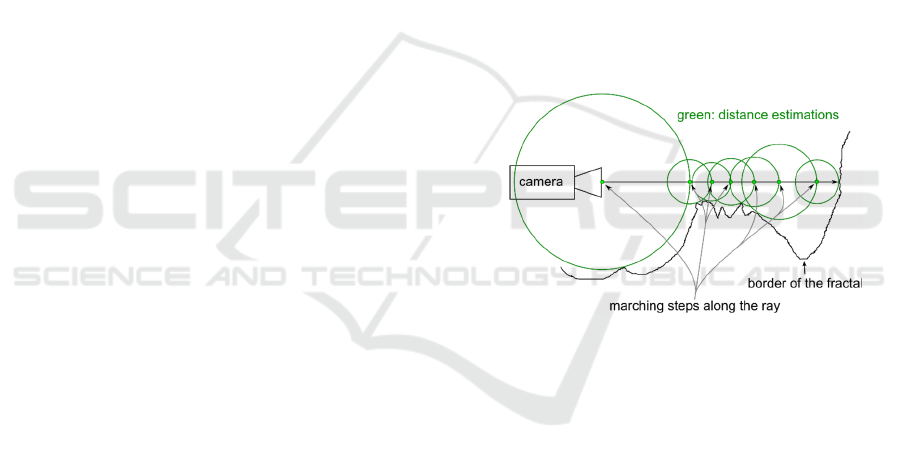
3.2 Raymarching Algorithm
Raymarching (also known as sphere tracing) is a form
of path tracing that estimates the coordinates of a ray
intersecting an object on the scene.
The ray is defined as a point in space r(t) in which
it currently is located and a direction. Placing of the
virtual camera defines the starting point r
o
for the first
iteration. Every pixel of the render target screen
requires at least one ray with direction calculated to
go through that pixel (multisampling can be used to
reduce any visual artifacts. In each iteration the
distance t means the longest distance that a ray can be
traced along its direction without intersection. The
location of a ray position is moved by that distance
and the algorithm “marches” in this way (Figure 1)
until the current t is not smaller than the pre-defined
value ϵ. Tradeoff between algorithm speed and
accuracy can be easily adjusted by changing the
parameters ϵ, maximum amount of steps and a
distance a ray can go forward. Usually, the algorithm
stops after finding the first intersection.
Figure 1: Illustration of raymarching algorithm.
Ambient occlusion can be deduced from the
number of steps taken before hitting an object. The
technique also allows to calculate shadows by casting
some additional rays starting from the original
intersection point. Normal vectors can be estimated
using gradient of partial derivatives calculated from
surface distance mappings with a small position shift
from the original intersection point.
3.3 Signed Distance Functions (SDF)
To calculate the maximum distance t, each object has
to be represented in a way that allows efficient
determination of the length between a ray’s current
position and the object’s surface. Signed distance
functions fulfill the purpose of storing the scene
description in a form convenient for raymarching.
Signed distance function f(x) is the function that
returns a distance (typically Euclidean) between any
given point x and object surface. Sign expresses the
GRAPP 2024 - 19th International Conference on Computer Graphics Theory and Applications
254
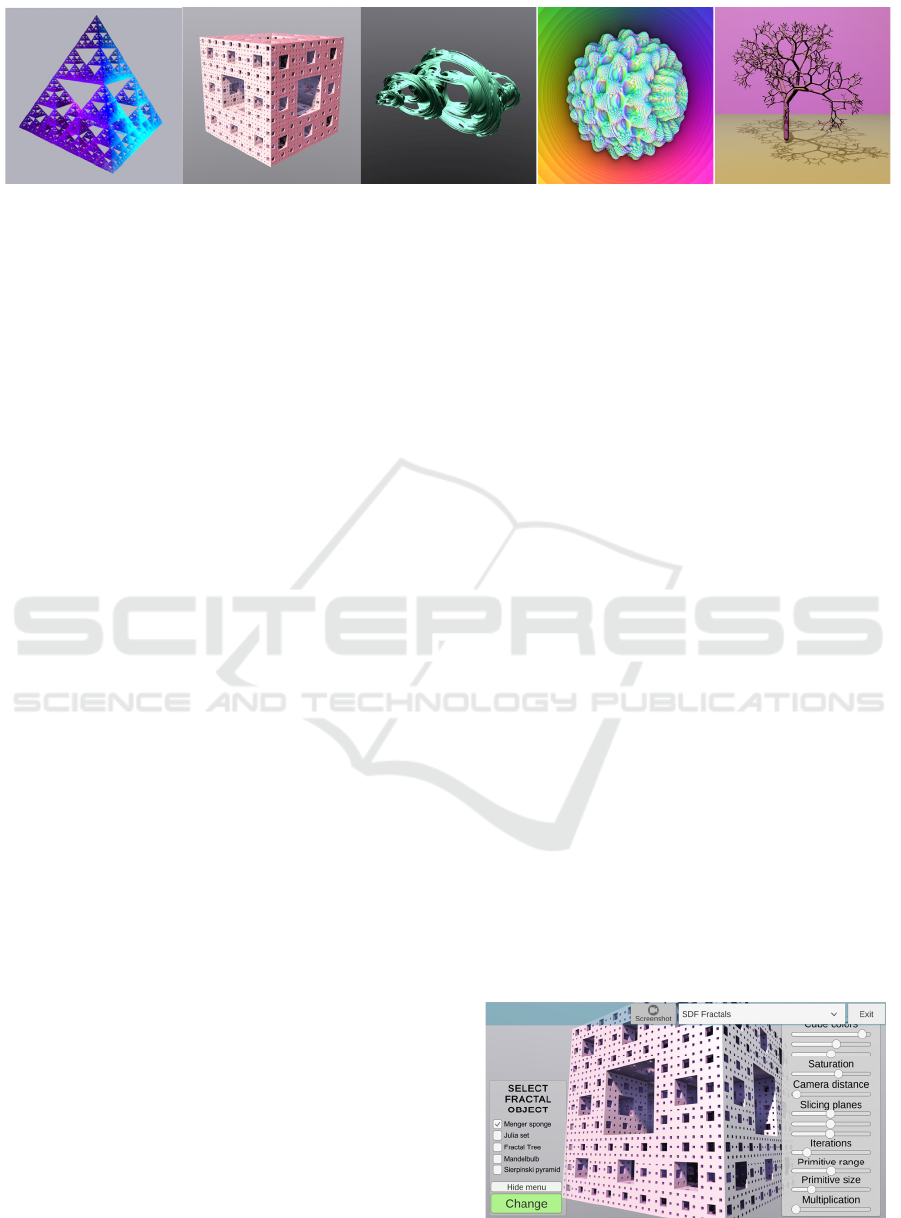
Figure 2: A set of 3D fractals available in the demonstration application. From left to right: Sierpinski pyramid, Menger
sponge, Julia set, Mandelbulb, fractal tree.
distinguishment between the inside and outside of a
given model.
In this approach the data is stored within code in
the form of mathematical functions and as such must
be first described using one from variety of model
definitions. Shapes like Menger sponge or Sierpinski
pyramid can be deconstructed into simple objects –
cubes, tetrahedrons, etc. Distance functions formulas
for primitive 3D shapes are relatively easy to define
and they can be used as input for SDF-based CSG
operations such as intersection, union, and difference.
Defining the CSG tree works the same as in any
typical mesh-represented 3D model. Moreover,
blending objects built using CSG primitives is very
easy with the usage of a polynomial smoothing
function. Working with symmetry and self-
repetitiveness of fractals is intuitive when described
by the distance function. Modulo operator allows for
creating foldings without the need for computational-
costly recursive iterations. By deciding on the amount
of foldings and repetitions one can produce a finite
approximation of an infinite fractal shape that will fit
the need and hardware possibilities.
Some fractal shapes do not have a continuous
surface that can be defined using primitive shapes and
for those signed distance functions are a great
alternative. 3D projection model of a four-
dimensional Julia set is mapped using the escape-time
algorithm based on quaternions. For others, like
Mandelbulb which is a 3D interpretation of
Mandelbrodt set, Cartesian coordinates are
transformed into polar to conduct some operations on
them and then converted back as an output.
Lindenmayer-systems can also be demonstrated
using SDFs. Starting with the basic branch shape
definition for each iteration the set of rules is applied
to transform, split, elongate, or rotate the shape to
form the tree. By changing the parameters growth
process and movement of a tree-like shape can be
simulated.
Bounding volumes optimization (used in other ray
tracing techniques) can be used. In the scene
definition more complex formation can be wrapped
within the simple ones like spheres. If the sphere is
missed by the ray, there is no point in calculating the
more complex function of the shape inside of it.
Proposed solution is not optimized in such way.
4 REALISATION AND RESULTS
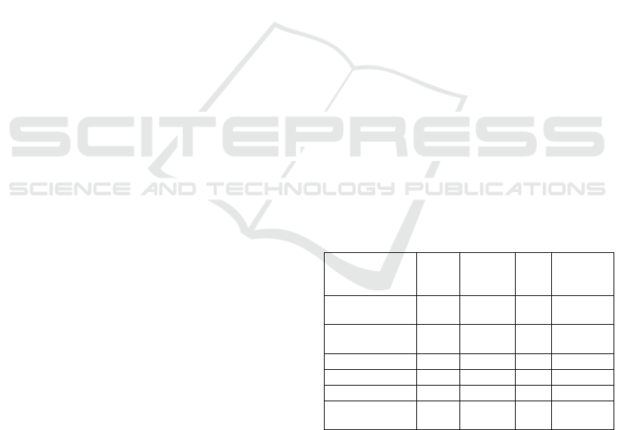
4.1 Demonstration Application
The developed demonstration application consists of
a set of scenes between which the user can switch.
The scenes present examples of fractal objects.
Objects and the camera move in time, and the user
can use sliders to change their most important
parameters.
The program is presenting examples of fractal
objects with SDF representation as well as boundary
representation. To display an object described using
distance estimators, surface is needed, with the
material of a given fractal assigned to it. The
implementation of the marching rays algorithm and
the description of the scene with a fractal object are
located in the pixel shader code assigned to the
material. Each fractal therefore has a separate
material with its own shader.
The following 3D fractals were implemented in
the software: Sierpinski pyramid, Menger sponge,
Julia set, Mandelbulb object, fractal tree – Figure 2.
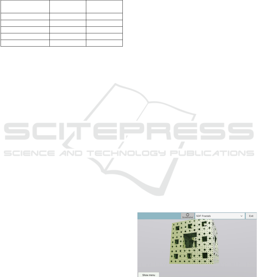
In Figure 3 the main window of the demonstration
application is shown.
Figure 3: View of the running demonstration application.
Efficiency of 3D Fractal Generation Through Raymarching
255
4.2 Environment, Software and
Hardware Dependencies
The demo application was prepared using the Unity
game engine on the MS Windows platform in 64-bit
architecture. Graphics pipeline is set using DirectX
11 and HLSL shaders. Intel Graphics Frame
Analyzer, PresentMon – tools for analyzing the
performance of graphic applications.
The research was carried out using graphics card:
Intel® Iris® Xe Graphics and NVIDIA® GeForce®
RTX 2060.
To perform generation performance analyses, the
Graphics Performance Analyzers toolkit version 21.2
was used. Additionally, to measure the average
duration of rendering frames – the PresentMon
application, version 1.8.1.
Example of a figure constructed recursively –
fragment of HLSL formula for the Sierpinski triangle:
float tetrahedron(float3 p){
p *= _Size;
return (max(abs(p.x+p.y)-p.z, abs(p.x-p.y)+
p.z)-(2.*_Size/3))/sqrt(3.0);
}
float sierpinski(in float3 p){
float scale = 2.5/_Size;
for (int n = 0; n < _Iterations; n++){
p *= 1.0/_Size;
if (p.x+p.y < 0.) { p.xy = -p.yx; }
if (p.x+p.z < 0.) { p.xz = -p.zx; }
if (p.y+p.z < 0.) { p.yz = -p.zy; }
}
return tetrahedron(p)*pow(scale,
int(-_Iterations));
}
An example of a distance mapping function for an
escape-time fractal – Julia’s set:
float julia(in float3 p, in float4 c){
float4 z = float4(p, 0.0);
float md2 = 1.0; float mz2 = dot(z, z);
for (int i = 0; i < _Iterations; i++){
md2 *= 4.0 * mz2;
z = quatsqr(z) + c;
mz2 = dot(z, z);
if (mz2 > 4.0) break;
}
float d = 0.25 * sqrt(mz2 / md2) * log(mz2);
return d;
}
5 RESULTS AND DISCUSSION
Several tests were carried out to assess the efficiency
of the implementation of the raymarching algorithm
and the use of hardware functions of the graphics
card. Tests were also carried out to assess the
application's memory usage. The set of generated
fractals included, for the version using SDF:
Sierpinski pyramid, Menger sponge, Julia set,
Mandelbulb object and fractal tree. For the boundary
representation, a Menger sponge was generated. The
analysis of the results also considered: functional
possibilities, difficulties in implementation and
efficiency of the solutions.
5.1 Efficiency of Realization
Considering hardware optimizations (use of the
graphics pipeline by the engine, use of shaders),
frame generation times were compared for the
following graphics cards: Intel® Iris® Xe Graphics
and NVIDIA® GeForce® RTX 2060. The efficiency
comparison for these cards is presented in Table 1.
Performance of the integrated GPU was presented
mostly for contrast to show that the implementation
performance heavily depends on the GPU with the
usage of pixel shaders. The comparison shows that
the demonstration application makes significant use
of the GPU.
Table 1: Comparison of implementation efficiency for
various fractal objects (FPS – Frames Per Second, HMT –
How Many Times the performance of GeForce 2060 is
better, RPS – Rays Per Second).
Scene (resolution
1920x1080
p
ixels)
FPS of
Iris Xe
FPS of
GeForce
2060
HMT
RPS of
GeForce
2060
Sierpinski
py
rami
d
SDF
5.6 59.6 10.6
123.6 ⋅ 10
6
Menger sponge
SDF
22.0 638.0 29.0
1323 ⋅ 10
6
Julia set SDF 4.78 35.0 7.3
72.6 ⋅ 10
6
Mandelbulb SDF 6.7 228.0 34.0
472.8 ⋅ 10
6
Fractal tree SDF 5.2 140.9 27.1
292.2 ⋅ 10
6
Menger sponge
b
oundar
y
re
p
r.
13.27 74.8 5.6
Not
a
pp
licable
Additionally, it is worth paying attention to the
comparison of performance for the same fractal
(Menger sponge) but in different implementations:
using raymarching and SDF and in the traditional
boundary representation. The SDF implementation is
almost 10 times faster than the naive procedural
generation using boundary representation (for the
GRAPP 2024 - 19th International Conference on Computer Graphics Theory and Applications
256
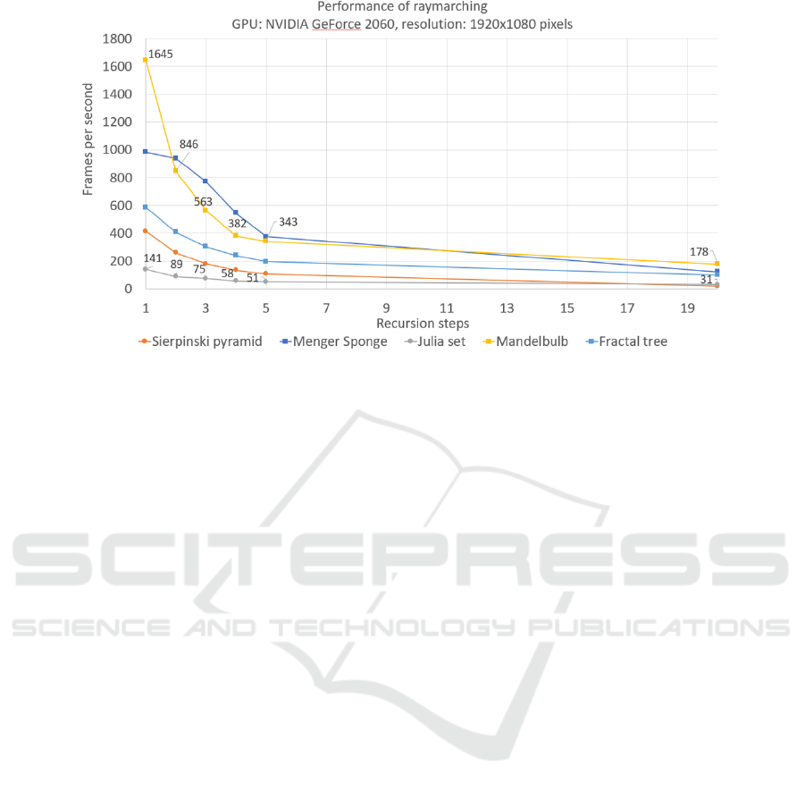
Figure 4: Efficiency of the raymarching algorithm.
GeForce card) and twice as fast as the static model
imported as a scene object. However, this comparison
may not be precise due to the multitude of
optimization possibilities in both techniques.
An analysis of the relationship between the
performance (FPS) of the raymarching algorithm and
the number of iterations was also carried out. This is
a very important problem, because only a sufficiently
large number of iterations ensures the expected visual
effect. The results are presented on a chart in
Figure 4. It is clearly visible that although the FPS
value varies depending on the mathematical
description and geometry, the trend of changes is
similar for any fractal. For a small number of
iterations, differences between fractals (geometry and
mathematical description) strongly affect the FPS
value. Since the frame rate was higher than the refresh
rate of the monitor screen (144Hz), frames were
collected using the GPA software to measure the
estimated performance. Due to the very short
duration, these measurements are characterized by a
high error (a difference of up to 10% between
subsequent measurements). Nevertheless, these
measurements prove a tendency for the generation
rate to decrease with increasing computational
complexity.
5.2 Memory Usage
The basic advantage of raymarching is saving the
memory needed to store data about the fractal model.
All necessary output is calculated on the fly, all is
stored in the code in a shape formula description.
Experiments were carried out for a Menger sponge in
both versions of implementation: raymarching with
SDF and the traditional boundary representation.
Despite differences in properties and mathematical
descriptions, different groups of fractals are based on
an iterative, recursive form of generation. This means
that for each fractal, the increase in the complexity of
the model will be exponential. Therefore, the
asymptotic increase in the number of elements will
always be described by an exponential function.
Therefore, the conclusions from the analysis of the
Menger sponge can be transferred to other fractals.
The asymptotic relationship will be the same up to a
constant.
Most algorithms for the procedural generation of
boundary representations involve dividing elements
into smaller parts and possibly transforming them.
For the Menger sponge, the number of vertices after
n iterations will be 8*20
n
. The vertices are stored in
memory for model reconstruction. Even if we assume
optimization of memory consumption, e.g. by
removing elements with duplicate coordinates, the
exponential growth quickly creates an object that
takes up so much memory that it may exceed the
application capabilities. For example, for the 5th
iteration we can get as many as 25,600,000 vertices.
Of course, we are talking about the maximum number
of vertices – in practice, some of them may be
rejected (effect of culling).
An experiment was performed with two Menger
sponges corresponding to the above theoretical
analysis. To make the comparison more reliable, an
imported ready-made static 3D model of the Menger
sponge with 5 levels of recursion was used. The
results (dumps of content from the graphics card
memory) are summarized in Table 2. Over 17 million
vertices are drawn for the boundary representation in
Efficiency of 3D Fractal Generation Through Raymarching
257
specific implementation conditions. Such
complicated models can be easily made using SDF –
creating not only 3D, but also real-time animated
fractal objects.
Table 2: Comparison of implementation efficiency for
different representations (Graphics card statistics).
Boundary
representation
Raymarching
with SDF
FPS
195.7 (5.1ms) 377.9 (2.6ms)
Tris 14.9 M 202
Verts 17.1 M 125
Mesh memory usage 329.6MB 1.0MB
Screen resolution 1920 x 1080 1920 x 1080
Presented implementation used pixel shaders and
DirectX® 11 pipeline for simplicity. It is worth
mentioning that in a modern API like Vulkan® or
DirectX® 12 when combining raymarching with
normal rendering, computer shader can be used
instead of pixel shader to better utilize the pipeline in
asynchronous manner and output whatever is needed
to a texture or directly to the render target view.
5.3 Functionality
Modeling with raymarching and SDF solves the
problem of efficiency and allows creating high-
resolution visualizations of fractal objects. The shape
of objects and the position of the camera change in
real time. A constant number of rays is used each time
to generate one image frame. The time needed for
calculations depends on which part of the frame the
displayed object occupies and the complexity of the
procedure of generating it (as shown in the chart in
Figure 4). For example, Mandelbulb in the first
iteration is just a sphere, which is the easiest shape to
calculate distance to.
Some fractals require less operations repeated in
each iteration to achieve the required result, so they
converge faster. A suitable number of iterations for
the given resolution is about 5 - more details cannot
be rendered without increasing the number of pixels
available. This is also the reason why the curves
stabilize – not much is changing in generating the
image and the amount of calculations become similar.
A different shape of curve for the Menger Sponge
is caused by the complexity of this algorithm being
exponential. In contrary to Sierpinski pyramid, where
all small tetrahedrons are drawn based on their
calculated position, Menger Sponge implementation
depends on the usage of CSG operations to cut the
holes inside the cube recursively.
The number of pixel shaders is related to the
screen resolution, multisampling, etc. and does not
change significantly with scene complexity. Profiling
the raymarching algorithm is not difficult because the
entire code is contained in one shader and there are
specific parameters responsible for the balance
between quality and generation speed (recursion
level, number of steps for the marching ray).
Calculating normal vectors allows to add lighting
simulations. When designing a display algorithm,
shading, anti-aliasing can be added, lighting
parameters and coefficient values changed.
Additionally, it is possible to use space folding
operations, CSG operations and processing of the
behavior of observed points (for example for Julia
sets). Creating a boundary representation for fractal
objects would be costly and very complicated.
Many stages of image generation (lighting
simulation, shading, anti-aliasing) require writing the
shader code yourself. However, those can be reused
for any objects if the mapping function returns the
distance between the position of the ray and the the
nearest object. Objects can be positioned relative to
each other, building increasingly complex scenes.
Adding shadow casting for the Menger sponge with
20 levels of recursion depth (Figure 5) reduces
performance from about 250 FPS to 165 FPS, but it is
still higher than the refresh rate of high-quality
displays. The shapes can also be replicated with a
small increase in generation time by using space
transformation operations. An important advantage of
using the path tracing is the ability to easily add visual
effects: ambient occlusion, glow. Additionally, this
happens without much larger computational costs.
The disadvantages of using the SDF include the
lack of sufficient accuracy. For the Menger sponge,
there are no visual differences when increasing the
recursion depth above 5, because individual cubes
begin to overlap.
Figure 5: Menger sponge’s shading effect.
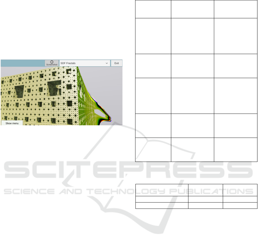
Objects may behave in a way that is difficult to
predict due to the multiple compositions of space –
Figure 6 and the multitude of iterative operations,
GRAPP 2024 - 19th International Conference on Computer Graphics Theory and Applications
258
forcing heuristic adjustment of appropriate
parameters. The lack of accuracy that results from
performing n calculations on floating-point numbers
limits the quality of generation more than the speed
of visualization itself. On the other hand, the lack of
continuity of solids caused by the use of space
transformations and some distance estimator
formulas means that even with increased image
resolution, obtaining a higher number of details could
prove problematic.
Figure 6: An example of undesirable distortion of the
Menger sponge.
5.4 Functionality Comparison of
Representations
Using the boundary representation is characterized by
low efficiency of image generation due to the rapidly
increasing number of calculations for geometric
transformations with increasing recursion levels.
However, there are ready-made methods of
displaying (rendering) the scene image, culling
optimizations, easy texturing, adding collision
components, and the ability to store the shape of
objects as appropriate data structures. The main
benefits of using the raymarching algorithm are
presented in Table 3.
With boundary representation, fractal objects can
be modeled volumetrically by adding primitives to
the scene via scripts. The fractal objects created in
this way cause a significant drop in the efficiency of
the generated image and, without the use of complex
hardware optimizations, do not match the level of
detail of objects described using raymarching with
SDF. Moreover, adding each additional object to the
scene means the need to process its vertices. The
largest number of recursion levels that have been
achieved in practice for the generated Menger sponge
is three (Table 4). Each subsequent level of recursion
results in an overflow in hardware memory, and
finally, forced termination of the program.
Table 3: Key benefits of using the raymarching algorithm.
Application
Raymarching
with SDF
Modelling with
boundary
re
p
resentation
Modelling of
non-
differentiable
surfaces
Accurate modeling,
tracking the escape
route of specific
points
Necessary use of
interpolation,
tessellation,
volumetric
modeling, even
when using RT
Modelling of
fractal tree
Creating many
branches and
multiplying trees at
low cost
Need to use
instancing
techniques to
maintain efficiency
Modeling
objects
recursively
based on
primitive shapes
Mostly linear
computational
complexity thanks
to the use of space
folding
Exponential
increase in
computational
complexity
depending on the
level of recursion
Technology
stack
Any 3D pipeline
engine that is able to
execute pixel or
com
p
ute shade
r
Requires usage of
3D modeling tools
Memory and
computational
cost
Low, structure in
the code,
calculations only for
what is visible
High, many vertices
to process, many not
visible
Table 4: The number of shader calls for scenes depicting a
Menger sponge with three levels of recursion.
Scene (resolution
1920x1080
p
ixels
)
Pixel shader
calls
p
er frame
Vertex shader
calls
p
er frame
Boundar
y
re
p
resentation 8809000 1054000
Ra
y
marchin
g
with SDF 7759000 7504
6 SUMMARY
The article presents how raymarching can be turned
into a well-suited solution for generating fractal
shapes using modern hardware. It can generate real-
time animated visualizations of three-dimensional
fractal models. Comparisons of different fractal
groups and modeling techniques were described.
Both speed and memory performance were studied.
Despite not utilizing most of the 3D pipeline features
the algorithm proved to be very efficient. Numerous
techniques of describing fractal shapes were explored
along with the parameters that allow for the shape,
color and camera manipulations.
SDFs provide a convenient tool for
mathematicians to define shapes and transformations
directly in code, without extensive knowledge of the
3D modeling tools. Raymarching can be incorporated
Efficiency of 3D Fractal Generation Through Raymarching
259

as a stage of a larger rendering solution or treated as
standalone.
There is a lot of potential to optimize raymarching
path tracer in a similar manner to a standard ray
tracing by implementing proper bounding volume
hierarchy and binary space partitioning.
On the Internet (Raymarching, 2020) you can find
the statement that “raymarching is the unappreciated
cousin of ray tracing”. Articles on this topic are rare.
The conducted research has shown that it is worth
addressing this issue. Moreover, the practical use of
raymarching with SDF can bring many measurable
benefits.
REFERENCES
Angramme (2021). Fractal_viewer. https://github.com/
Angramme/fractal_viewer. (Accessed 10 December
2023).
Ansari, M.Y. (ed.), (2011), Game Development Tools, CRC
Press,
Barnsley, F.B. (2012). Fractals Everywhere: New Edition.
Dover Publications Inc.; 3rd revised edition.
Berkman, M.I., Akan, E. (2019). Presence and Immersion
in Virtual Reality. In: Lee, N. (eds) Encyclopedia of
Computer Graphics and Games. Springer, Cham.
https://doi.org/10.1007/978-3-319-08234-9_162-1.
Bovenzi, T. (2022). Ray Marching. https://www.
tylerbovenzi.com/RayMarch/ (Accessed 10 October
2023).
Foley, J.D., van Dam, A., Feiner, S.K., Hughes, J.F. (1990).
Computer Graphics Principles and Practice, sec. ed.
Addison-Wesley.
Glassner, A.S. (1989). An Introduction to Ray Tracing,
Morgan Kaufmann.
Granskog, J. (2017). CUDA Ray Marching.
https://granskog.xyz/blog/2017/1/11/cuda-ray-
marching. (Accessed 10 December 2023).
Hart, J.C., Sandin, D.J., Kauffman, L.H. (1989). Ray
Tracing Deterministic 3-D Fractals. ACM SIGGRAPH
Computer Graphics. 23 (3), July 1989. 289–296.
https://doi.org/10.1145/74334.74363.
Hart. J.C. (1996). Sphere Tracing: A Geometric Method for
the Antialiased Ray Tracing of Implicit Surfaces. The
Visual Computer. 12. 527–545. https://doi.
org/10.1007/s003710050084.
Mandelbrodt, B.B. (1983). The fractal geometry of nature.
W.H.Freeman & Co Ltd.
Mesh Distance Fields. (2023). Mesh Distance Fields.
https://docs.unrealengine.com/4.27/en-
US/BuildingWorlds/LightingAndShadows/MeshDista
nceFields/. (Accessed 10 October 2023).
Peitgen, H-O., Hartmut, J., Saupe, D. (2013). Chaos and
Fractals: New Frontiers of Science. New York:
Springer-Verlag.
Perlin, K., Hoffert, E.M. (1989). Hypertexture. ACM
SIGGRAPH Computer Graphics. 23 (3). 253–262.
https://doi.org/10.1145/74334.74359.
Petrov St. (2020). 3D-Fractal-Mandelbulb-Raymarching.
https://github.com/StanislavPetrovV/3D-Fractal-
Mandelbulb-Raymarching. (Accessed 10 December
2023).
Prusinkiewicz, P., Lindenmayer, A. (1996). The
Algorithmic Beauty of Plants, http://
algorithmicbotany.org/, Author’s electronic version of
Springer Verlag book from 1996. (Accessed 10 October
2023).
Raymarching (2016). Raymarching Distance Fields:
Concepts and Implementation in Unity. https://
adrianb.io/2016/10/01/raymarching.html. (Accessed 10
October 2023).
Raymarching (2020). Ray marching tutorial Series' Articles.
https://dev.to/ramislicer/series/8991. (Accessed 10
October 2023).
Roth, S. (1982). Ray Casting for Modeling Solids.
Computer Graphics and Image Processing. 18(2), 109–
144. https://doi:10.1016/0146-664X(82)90169-1.
SDF fonts. (2023). About SDF fonts. In: Unity manual.
https://docs.unity3d.com/Packages/com.unity.textmes
hpro@4.0/manual/FontAssetsSDF.html. (Accessed 10
October 2023).
Shriwise, P.C., Davis, A., Jacobson, L.J., Wilson, P.H.
(2017). Particle tracking acceleration via signed
distance fields in direct-accelerated geometry Monte
Carlo. Nuclear Engineering and Technology. 49 (6).
1189-1198. https://doi.org/10.1016/j.net.2017.08.008.
Slater, M. (2003). A note on presence terminology.
Presence Connect 3(3), 1–5.
Tomczak, L.J. (2012). GPU Ray Marching of Distance
Fields. Technical University of Denmark.
Tuy, H. and Tuy, L. (1984). Direct 2-D Display of 3-D
Objects. IEEE Computer Graphics and Applications. 4
(10). 29-34. https://doi.org/10.1109/MCG.1984.
6429333.
Walczyk M. (2023). Ray Marching.
https://michaelwalczyk.com/blog-ray-marching.html
(Accessed 10 October 2023).
Watt, A. (2000). 3D Computer Graphics, 3rd ed. Addison-
Wesley.
Wong, J. (2016). Ray Marching and Signed Distance
Functions. https://jamie-wong.com/2016/07/15/ray-
marching-signed-distance-functions/. (Accessed 10
October 2023).
GRAPP 2024 - 19th International Conference on Computer Graphics Theory and Applications
260
