
Heuristic Methods for the Antenna-Constrained Beam Layout
Optimization on Multibeam Broadcasting Mission
Camille Lescuyer
1
, Christian Artigues
2
, Jean-Thomas Camino
1
and C
´
edric Pralet
3
1
Airbus Defence and Space, 31 Rue des Cosmonautes, 31402, Toulouse, France
2
CNRS, LAAS, 7 Avenue du Colonel Roche, F-31400, Toulouse, France
3
ONERA/DTIS, University of Toulouse, 2 Avenue Edouard Belin, 31400 Toulouse, France
Keywords:
Telecommunication Satellite, Television Broadcasting, Linguistic Beam, Heuristic, Graph Coloring.
Abstract:
In this paper, we tackle a payload design problem for a broadcasting mission where a telecommunication
satellite must provide television services to distinct regions defined as polygons. To cover these polygons,
several telecommunication beams are emitted by the satellite, with the risk that they mutually degrade their
performance while also being hard to accommodate mechanically on the spacecraft. The problem is to de-
termine a set of non-conflicting beams that cover all the regions and optimize a performance metric related
to the sizes of the beams used. The first method is a matheuristic exploiting iterative solv of an ILP model.
The second method, called the merge-and-split heuristic, is inspired by Iterated Local Search and reuses a fast
graph coloring algorithm to analyze conflicts among selected beams. These two methods are evaluated on
realistic instances, the largest one involving more than one hundred regions to cover.
1 INTRODUCTION
Telecommunication satellites are major assets used
by operators to provide coverage in remote areas at
a lower cost than terrestrial networks. As operators
require an increasing quantity and quality of the ser-
vices they provide, satellites must optimize their on-
board resources. Therefore, satellite manufacturers
need the support of optimization techniques to help
them find payload design solutions that reach the mis-
sion requirements while complying with the full set of
operational and design constraints. One of these so-
lutions consists in using multiple beams to increase
the capacity without expanding the frequency spec-
trum, as the same frequency band can be used by sev-
eral beams. Moreover, using multiple beams requires
using dedicated antenna technologies such as Single-
Feed-Per-Beam (SFPB), which is cost-effective and
can reach high-performance radio frequencies. How-
ever, SFPB introduces beam layout constraints. Each
beam is created by a so-called feed horn (or feed, see
Fig. 1), whose size and shape can be computed be-
forehand given the target region to be served, and each
beam is allocated to a certain reflector (parabolic an-
tenna available onboard). As shown in Fig. 2, one
issue is that it can turn out that the positions required
for two feeds on the same reflector are not compatible
with each other for geometrical reasons if the target
regions are too close.
To optimize the design of telecommunication
satellites while considering beam layout constraints,
several approaches have been studied. (Kyrgia-
zos et al., 2013) explores non-uniform beam sizes
and bandwidth allocation among beams to maximize
inter-beam distance. (Camino, 2017) incorporates
antenna constraints into a non-uniform beam lay-
out, leveraging graph coloring techniques for beam-
to-reflector allocation. A patent by (Hammill and
Dishaw, 2004) presents a method for generating non-
uniform beams based on population density within
specific polygons. (Contardo and Hertz, 2021) pro-
poses an exact algorithm to cover polygons with a set
of disks, but do not address the beam-to-reflector al-
location problem.
In this paper, we introduce two heuristic meth-
Figure 1: Beams of differ-
ent sizes and their associ-
ated feeds.
Figure 2: A conflict be-
tween two feeds.
294
Lescuyer, C., Artigues, C., Camino, J. and Pralet, C.
Heuristic Methods for the Antenna-Constrained Beam Layout Optimization on Multibeam Broadcasting Mission.
DOI: 10.5220/0012380200003639
Paper published under CC license (CC BY-NC-ND 4.0)
In Proceedings of the 13th International Conference on Operations Research and Enterprise Systems (ICORES 2024), pages 294-301
ISBN: 978-989-758-681-1; ISSN: 2184-4372
Proceedings Copyright © 2024 by SCITEPRESS – Science and Technology Publications, Lda.

ods for beam layout design in SFPB antennas, aim-
ing to fulfill the requirements of telecommunication
missions. Our primary objective is to provide ser-
vice to as many requested regions as possible while
ensuring a satisfactory quality of service. In this de-
composed optimization scheme where the beam lay-
out is the first step, the quality of service cannot be
accurately evaluated at this stage where important de-
sign steps subsequent to the beam layout optimiza-
tion are missing (frequency allocation, definition of
all payload routes, TV channels assignment, ampli-
fiers sizing, power distribution, etc.). However, we
can still create beams having a small size to maxi-
mize the power spectral densities and enhance signal
quality for ground receivers. In the end, our goal is
to select small beams that cover as many regions as
possible, while preventing feed conflict assignments
among beams allocated to the same reflector.
The rest of the paper is organized as follows: Sec-
tion 2 presents the formal problem definition using In-
teger Linear Programming (ILP). Section 3 introduces
a matheuristic approach that iteratively enlarges a set
of candidate beams. Section 4 describes a heuristic
algorithm called merge-and-split. Section 5 provides
experimental results on various instances. Finally,
Section 6 concludes the paper and outlines potential
future developments.
2 PROBLEM DEFINITION
2.1 Telecommunication Mission
The mission is defined by a set of regions on the
Earth’s surface. The geometrical definition of a re-
gion is a polygon defined by the set of successive ver-
tices placed on its boundary, and each region has its
own demand expressed in terms of number of televi-
sion channels. The segmentation of the market in ge-
ographical areas can be made for linguistic reasons or
because of the economical context. In the following,
the set of polygons to cover is referred to as P.
2.2 Beams
General Beams. We can define a beam as a disk
that covers a specific area on the Earth’s surface
served by the satellite communication system. More
formally, a beam is a pair b = (c
b
, r
b
) where c
b
is
the center of the beam (defined by a longitude and
a latitude) and r
b
is the radius of the disk associated
with the beam, expressed in degree angle. For signal
quality reasons, the radius of all the beams considered
must not be greater than a maximum value referred to
as MaxRadius.
Smallest Covering Beams. In the following, we
consider specific kinds of beams that are directly de-
fined by the set of polygons they cover. Using the
Welzl algorithm (Welzl, 2005), we can find the small-
est beam b = (c
b
, r
b
) covering a subset P
′
⊆P in O(n)
time. Here, n is the number of polygons in P
′
. The
Smallest Covering Beam for a set P
′
⊆ P is denoted
as SCB(P
′
), and the covered polygons are denoted as
P
b
.
One combinatorial challenge arises: if a beam can
be defined from any set P
′
⊆ P, then there are 2
|P|
candidate beams.
Conflicts Between Beams. As mentioned in the in-
troduction, the SFPB antenna is characterized by a
limited set of reflectors, usually three or four. Each re-
flector is associated with a cluster of feeds, as shown
in Figure 2. Each feed is the hardware equipment as-
sociated with a single beam, and the reflector focuses
the signal and reflects the beam on the Earth’s surface.
Two beams whose disks are close on the Earth’s
surface and that are allocated to the same reflector
can create a conflict on their associated feeds. To pre-
vent conflicts, a minimum separation distance is im-
posed on the Earth’s surface. Formally, for two beams
b
1
= (c
b
1
, r
b
1
) and b
2
= (c
b
2
, r
b
2
) assigned to the same
reflector, the CONFLICT(., .) predicate is defined as
follows:
CONFLICT(b
1
, b
2
) : dist(c
b
1
, c
b
2
) < κ(r
b
1
+ r
b
2
) (1)
Here, dist(c, c
′
) is the Euclidean distance between
points c and c
′
in the longitude-latitude plane, and
κ > 1 is a fixed parameter determined by the satellite
manufacturer. In this context, κ =
√
3 is considered,
reflecting recent observations in related satellite man-
ufacturing activities.
From an operations research perspective, the beam
separation constraints can be represented using a
graph coloring problem. Indeed, let B
s
denote the set
of beams selected. We can build a graph G(B
s
) called
the feed conflict graph, containing one node per beam
in B
s
and one edge between two nodes associated with
beams b
1
, b
2
such that CONFLICT(b
1
, b
2
) takes value
true. Then, a set of beams is mechanically imple-
mentable if the chromatic number of G(B
s
), referred
to as γ(G(B
s
)), is less than or equal to the number of
reflectors, so that the beams can be distributed among
the different reflectors.
Heuristic Methods for the Antenna-Constrained Beam Layout Optimization on Multibeam Broadcasting Mission
295

2.3 Input Data
For a particular beam layout problem, we consider the
following input data:
• P = {p
1
, p
2
, . . . , p
N
P
}: set of polygons to cover;
• R = {1, 2, . . . , N
R
}: set of reflector indices;
• B = {b
1
, b
2
, . . . , b
N
B
}: set of candidate beams; the
radius of all these candidate beams is assumed to
be consistent with parameter MaxRadius;
• I ⊂ B ×B: pairs of beams which cannot be as-
signed to the same reflector (incompatible beams).
Moreover, for every p ∈ P, we denote as B
p
⊆ B the
set of beams in B that cover polygon p, that is the set
of beams b ∈ B such that p ∈ P
b
.
2.4 ILP Definition
Defining a solution of the beam layout problem means
(1) selecting a subset of the candidate beams to cover
polygons, and (2) associating a reflector with each se-
lected beam so that the reflector-to-beam allocation
is feasible. Such a problem can be formalized as an
Integer Linear Program using the following variables:
• z
p
∈ {0, 1}, p ∈ P : binary variable taking value 1
if and only if polygon p is covered by a selected
beam;
• x
b,r
∈ {0, 1}, b ∈ B, r ∈ R : binary variable taking
value 1 if and only if beam b is allocated to reflec-
tor r.
The ILP model proposed is given in Equations 2 to 5.
maximize M ·
∑
p∈P
z
p
−
1
|B|
∑
b∈B,r∈R
r
2
b
x
b,r
(2)
subject to ∀p ∈P,
∑
(b,r)∈B
p
×R
x
b,r
≥ z
p
(3)
∀p ∈P, ∀b ∈ B
p
,
∑
r∈R
x
b,r
≤ z
p
(4)
∀r ∈ R, ∀(b
1
, b
2
) ∈ I, x
b
1
,r
+ x
b
2
,r
≤ 1 (5)
The objective function given in Equation 2 tries to
both maximize the number of polygons covered (term
∑
p∈P
z
p
) and minimize the size of the beams used
(term −
1
|B|
∑
b∈B,r∈R
r
2
b
x
b,r
). To express that the main
goal is to maximize the coverage of the polygons,
a large constant M = MaxRadius
2
is used to weight
the first term, which leads to a lexicographic objec-
tive function. Constraint 3 ensures that if a polygon
is covered, then at least one of its covering beams is
selected. Constraint 4 ensures that if a polygon p
is not covered, then none of the beams covering p
is selected. As z
p
is a binary variable, it also states
that a beam is associated with at most one reflec-
tor. Last, Constraint 5 expresses that two conflicting
beams cannot use the same reflector.
2.5 Complexity
While we plan to prove the NP-hardness of the beam
layout problem considered, we can refer to closely
related problems from the literature that are already
known to be NP-hard. One notable similarity can
be observed with various NP-complete covering and
packing problems (Fowler et al., 1981). For example,
the 3-colorable unit disk covering problem involves
finding a set of unit disks and assigning a distinct
color to each disk such that the union of the disks
covers all given points, and overlapping disks have
different colors. This problem is proven NP-hard in
(Biedl et al., 2021). In another direction, the beam
layout problem addressed in (Camino, 2017) consid-
ers a set of points to be covered by beams, with each
point having a traffic demand. The objective is to find
a beam layout, including the beam-to-reflector assign-
ment, that maximizes the total traffic. This problem is
proven NP-hard through a polynomial reduction from
the Circle-Covering problem. It is important to note
that our problem differs in that we aim to maximize
the number of polygons covered by beams of small
sizes, rather than maximizing the total traffic associ-
ated with a set of covered points.
3 MATHEURISTIC METHOD
As mentioned before, enumerating all candidate
beams is exponential in the number of polygons and
is not practicable. For example, for an instance in-
volving only 20 polygons, there can be up to 1048576
possible subsets of polygons and as many potential
beams. This is why we propose a matheuristic method
that solves the ILP several times, on a restricted pool
of candidate beams B that evolves during the itera-
tions. Iterations are performed until a solution cover-
ing all the polygons is found or until a maximum CPU
time is reached. Also, one of the modelling issues
in the ILP presented in Section 2.4 is the fractional
part of the criteria in Equation 2 (
1
|B|
∑
b∈B,r∈R
r
2
b
x
b,r
),
referred as MSRS for Mean Squared Radius Sum in
this paper. The latter is fractional and difficult to im-
plement, we will then use the following criterion in
this first method:
maximize M ·
∑
p∈P
z
p
−
∑
b∈B,r∈R
r
2
b
x
b,r
with M =
∑
b∈B
r
2
b
+ 1
ICORES 2024 - 13th International Conference on Operations Research and Enterprise Systems
296

3.1 Detailed Description
The matheuristic is provided in Algorithm 1. Ini-
tially, the set of candidate beams B only contains all
the smallest beams covering a single polygon in P
and all the smallest beams covering two polygons in
P. Based on these candidate beams, it is possible to
compute the set I containing the pairs of incompat-
ible beams and to solve the ILP model given before
for input data P, R, B, I. In Algorithm 1, this is
achieved through a call to a function solveILP, that
returns the set of beams B
s
selected in the solution
of the ILP presented in Section 2.4. More formally,
if y denotes the value of a variable y after optimiza-
tion, then B
s
← solveILP(P, R, B, I) is equivalent to
B
s
← {b ∈ B |
∑
r∈R
x
b,r
= 1}. Altogether, the beams
in B
s
cover a set of polygons P
s
= ∪
b∈B
s
P
b
. The algo-
rithm iteratively improves the current solution by gen-
erating a set of new beams to expand the set B while
there are uncovered polygons and available compu-
tation time. It updates beam incompatibilities and
solves the enlarged ILP model, potentially refining the
beam selection strategy. The algorithm returns the last
beam selection found and, if there’s a maximum CPU
time for each solveILP call, it can also return the best
solution across iterations based on the objective func-
tion provided in Equation 2. Notably, in Algorithm 1,
cpuTime() denotes the current computation time, and
TimeLim represents the global CPU time limit.
Input: P: set of polygons to cover; R: set of
reflector indices
B ← initBeams(P);
I ← initIncomp(B);
B
s
← solveILP(P, R, B, I) ;
P
s
← ∪
b∈B
s
P
b
;
while P
s
̸= P and cpuTime() ≤ TimeLim do
B
g
← generateNewBeams(B
s
, P);
I
g
← generateNewIncomp(B
g
, B);
(B, I) ← (B ∪B
g
, I ∪I
g
);
B
s
← solveILP(P, R, B, I) ;
P
s
← ∪
b∈B
s
P
b
end
return B
s
Algorithm 1: Pseudocode of the matheuristic.
3.2 Beam Generation Heuristic
In the proposed matheuristic method, the main chal-
lenge lies in devising an effective strategy for gen-
erating beams that can be added to the current pool.
Several approaches have been tested, but in this para-
graph we only discuss the one that yielded the best
results thus far. The method involves enlarging the
pool of beams with new beams that cover subsets of
polygons with increasing cardinality during each it-
eration. To achieve this, we introduce a parameter
called NbPolyLimit. Initially, we set NbPolyLimit to
2, enabling the generation of beams that individually
cover one or two polygons. In each iteration, solving
the Integer Linear Programming (ILP) problem pro-
duces a set of selected beams denoted as B
s
. If B
s
does
not cover all the polygons, we increment NbPolyLimit
by one unit and generate beams b by merging two
beams from the solution. The resulting beams b cover
at most NbPolyLimit polygons and are added to the
pool. Formally, we compute
B
g
= {b = SCB(P
b
1
∪P
b
2
)| (6)
(b
1
, b
2
∈ B
s
) ∧(r
b
≤ MaxRadius)
∧(|P
b
| ≤ NbPolyLimit)}
4 MERGE-AND-SPLIT
The ILP manipulated in the previous sections has lim-
itations on instances containing more than 100 poly-
gons. To overcome this limitation, we define a spe-
cific heuristic that is independent of the ILP formal-
ization, called the merge-and-split heuristic.
4.1 Global Description
Globally, the merge-and-split heuristic is inspired
from Iterated Local Search (Lourenc¸o et al., 2003),
which alternates between optimization phases where
local moves are performed to try and improve the cur-
rent solution (beam merging moves in our case), and
a perturbation phase where the features of the cur-
rent solution are randomly updated (split operations
in our case). The merging phase consists in replac-
ing two beams b
1
and b
2
by the smallest beam cov-
ering all the polygons covered by b
1
and b
2
. The
selection of the beams involves randomness to di-
versify the exploration of the search space. Beam
merging operations aim at providing a new conflict
graph that is easier to color than the current graph
and are performed until reaching a colorable graph
or until a maximum number of merging operations
is reached. At that point starts the splitting process
of some beams, where splitting a beam b covering a
set of polygons P
b
means replacing b with the set of
individual beams {SCB({p}) |p ∈ P
b
} covering each
polygon served by b. Each time a feasible solution has
been found, it is evaluated according to the MSRS cri-
teria. We fix a total time limit, and we return the best
solution found at the end of the process. The merge-
and-split heuristic proposed is described in Figure 3.
Heuristic Methods for the Antenna-Constrained Beam Layout Optimization on Multibeam Broadcasting Mission
297
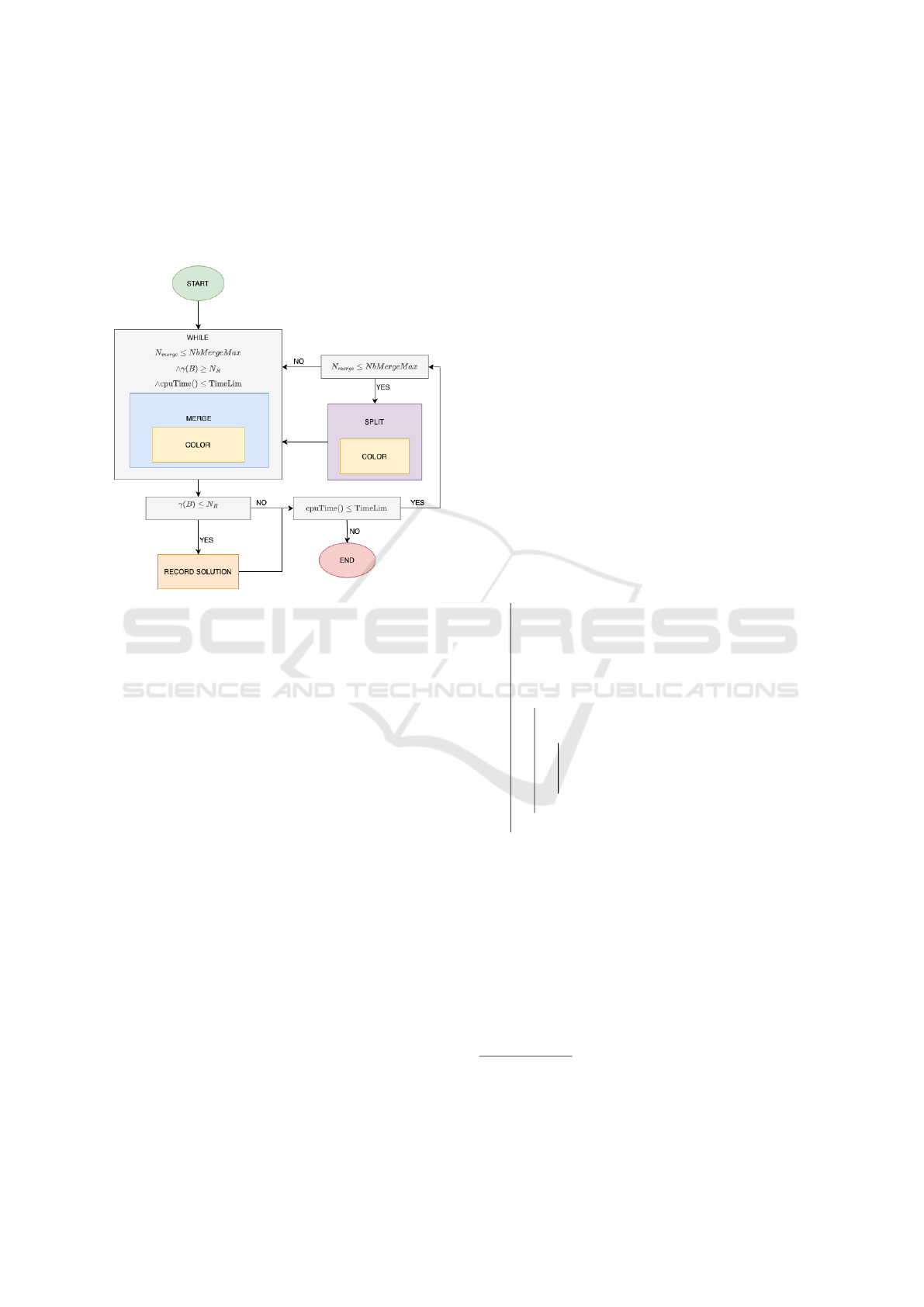
It starts from a set of beams B containing the small-
est covering beam associated with each polygon in P,
i.e. B = {SCB({p})|p ∈P}. By definition, this set of
beams covers all the polygons in P. In the following,
we detail the three main components of the algorithm,
that is the coloring, merging, and split procedures.
Figure 3: Merge-and-split algorithm.
4.2 Coloring Method
Each time the current set of beams B is updated, a
function needs to color the corresponding feed con-
flict graph. This function is called many times during
the algorithm and needs to be fast, even if determin-
ing whether a graph can be colored using a restricted
number of colors is NP-complete. Therefore, we de-
cided to reuse DSATUR (Br
´
elaz,1979). DSATUR is
a greedy algorithm that colors nodes with the highest
degree first. Each node is assigned the lowest feasible
color, considering its neighboring nodes’ colors. If
DSATUR manages to color the graph using no more
than N
R
colors, a consistent beam-to-reflector alloca-
tion exists. We denote the number of colors used by
DSATUR as
ˆ
γ(G(B)), which serves as an upper bound
on the actual chromatic number γ(G(B)).
4.3 Merging Mechanisms
The pseudocode of the merging process is sketched
in Algorithm 2. As expressed in the condition of the
while loop, merging operations are performed while
the chromatic number of current feed conflict graph
G(B) exceeds N
R
and there is some computation time
left and the number of merge operations does not ex-
ceed a limit referred to as NbMergeMax
1
.
At each step, the merging loop selects a candidate
pair of beams (b
1
, b
2
) in Cand, according to a merg-
ing method randomly chosen (more details later on
this point). The merged beam is accepted if and only
if it is feasible according to parameter MaxRadius,
but also if the estimated chromatic number of G(B
′
)
with B
′
←(B \{b
1
, b
2
}) ∪{b
3
} is lower than or equal
to the estimated chromatic number of the feed conflict
graph G(B) (i.e.,
ˆ
γ(G(B
′
)) ≤
ˆ
γ(G(B))). Indeed, merg-
ing two beams can also create new edges in the feed
conflict graph. As illustrated in Figure 4, beam 10
created by merging beams 3 and 4 has a conflict with
beam 9 that was not in conflict with the two beams
merged. Finally, the set of candidate beams Cand is
updated to avoid selecting several times the same pair
of beams, and the number of merging operations is
incremented.
Input: B: set of beams in the current solution
NbMerge ← 0
Cand ← {(b
1
, b
2
)|b
1
, b
2
∈ B, b
1
≺ b
2
}
while
ˆ
γ(G(B)) > N
R
and
Cand ̸=
/
0 and
cpuTime() ≤ TimeLim and
NbMerge ≤ NbMergeMax do
m ← select merging
method(ProbMergMethod)
(b
1
, b
2
) ← select a pair in Cand given m
Cand ← Cand \{(b
1
, b
2
)}
b
3
← SCB(P
b
1
∪P
b
2
)
if r
b
3
≤ MaxRadius then
B
′
← B ∪{b
3
}\{b
1
, b
2
}
if
ˆ
γ(G(B
′
)) ≤
ˆ
γ(G(B)) then
B ← B
′
Cand←Cand∪{(b
3
, b)|b ∈B
′
\{b
3
}}
NbMerge ← NbMerge + 1
end
end
end
Algorithm 2: Merging loop.
In the following, we define three heuristics to se-
lect the two beams b
1
, b
2
to merge at each step.
Merging Method 1 (M1). The first merging heuris-
tic favors the creation of small beams. To diver-
sify the search process, we select a pair (b
1
, b
2
)
leading to a merged beam b
3
that is among the
⌈|B|
2
× RatioSelectedBeams⌉ smallest ones. Here,
1
As we only merge beams two by two, the highest num-
ber of merging operations is always |P|−1. We consider a
smaller value for NbMergeMax in order to favor the explo-
ration of solutions containing a larger number of beams
ICORES 2024 - 13th International Conference on Operations Research and Enterprise Systems
298

(a) Before merging.
(b) After merging.
Figure 4: Impact of beam merging on the feed conflict
graph.
RatioSelectedBeams ∈]0, 1] is a parameter that allows
us to control the number of candidate pairs considered
at each step, that is the degree of diversification.
Merging Method 2 (M2). The second merging
heuristic favors the selection of two beams b
1
, b
2
that
have the highest number of common neighbors in
graph G(B). As illustrated in Figure 4b, the under-
lying idea is to make the coloring of these common
neighbors easier. In Figure 4, beams 3 and 4 have
four common neighbors, the merging of this pair of
beams deletes 10 edges and creates 7 ones, reducing
the total number of edges in the graph. Similarly to
M1, in order to diversify the search process, merging
method M2 randomly selects a pair of beams among
the ⌈|B|
2
×RatioSelectedBeams⌉ highest quality ones.
Merging Method 3 (M3). This third method first
selects a beam b for which the index of the color as-
signed by DSATUR is strictly greater than the num-
ber of reflectors available. This beam is then merged
with a beam b
′
that is selected following either a rule
inspired from method M1, or a rule inspired from
method M2, or a rule that merges b with its closest
neighbor. The method for selecting the second beam
is chosen randomly among these three methods.
4.4 Splitting Mechanisms
The splitting procedure selects ⌈β ×|B|⌉ beams in B,
with a selection according to a probability distribution
that is proportional to the beam size. The procedure
can be called in two different cases:
• DSATUR manages to color the current set of
beams using no more than N
R
colors, then β = β
m
and should be low enough to try and improve the
current solution and not restart all over again, but
not too low to favor the exploration of other parts
of the search space
• NbMergeMax has been reached, then, β = β
M
and
should be higher in order to try and remove incon-
sistencies in the current solution.
4.5 Parameters
In the end, the merge-and-split heuristic uses sev-
eral parameters. TimeLim is the maximum duration
of the process; NbMergeMax is the maximum num-
ber of merging operations performed before splitting
some beams; ProbMergMethod = [p
M1
, p
M2
, p
M3
] is
the selection probability for each merging method;
RatioSelectedBeams is the proportion of beam pairs
among which the beam merging method selects a
good alternative; β
m
is the ratio of beams to split when
the current solution is colorable using no more than
N
R
colors; β
M
is the ratio of beams to split when the
current solution is not feasible.
5 EXPERIMENTS
Experimental Setup. The matheuristic and merge-
and-split methods have been implemented in Python.
The ILP problems have been solved using CPLEX
12.10. The runs were made on a server with 96 cores
of an Intel(R) Xeon(R) Gold 5318Y CPU @2.10GHz
processor and 62GB of RAM. CPLEX exploits all
96 cores, while the merge-and-split heuristic runs on
a unique core. This difference must be considered
in the analysis of the experimental results, but for
the heuristic our goal is to build a fast method any-
way. We consider a telecommunication satellite hav-
ing N
R
= 4 reflectors. The methods were tested on
six instances, corresponding to sets of polygons P
mapped on France, Italy, West Europe, and Central
Europe. The last two instances correspond to the Cen-
tral Europe instance split into two parts that are called
Central Europe Part1 and Central Europe Part2. If we
covered each of the polygons of the four instances us-
ing one beam per polygon, we would obtain a feed
conflict graph G
0
= (B
0
, E
0
) whose features are given
in Table 1.
Table 1: Features of the instances.
Instance Notation |P| |E
0
| γ(G
0
)
France F 22 144 10
Italy I 30 128 8
West Europe W 92 467 9
Central Europe C 103 893 12
C Part 1 C1 52 294 10
C Part 2 C2 51 402 11
To evaluate the efficiency of each algorithm, we
analyze the number of polygons covered by the solu-
tion found and the number of beams selected in this
Heuristic Methods for the Antenna-Constrained Beam Layout Optimization on Multibeam Broadcasting Mission
299
solution. We also analyze the Mean Squared Radius
Sum given by
MSRS =
∑
b∈B
s
r
2
b
|B
s
|
where B
s
stands for the set of beams selected
in the final solution. For the merge-and-split
heuristic, we use 0.2 for β
m
; 0.8 for β
M
;
[0.2, 0.7, 0.1] for ProbMergMethod and finally 0.2 for
RatioSelectedBeams.
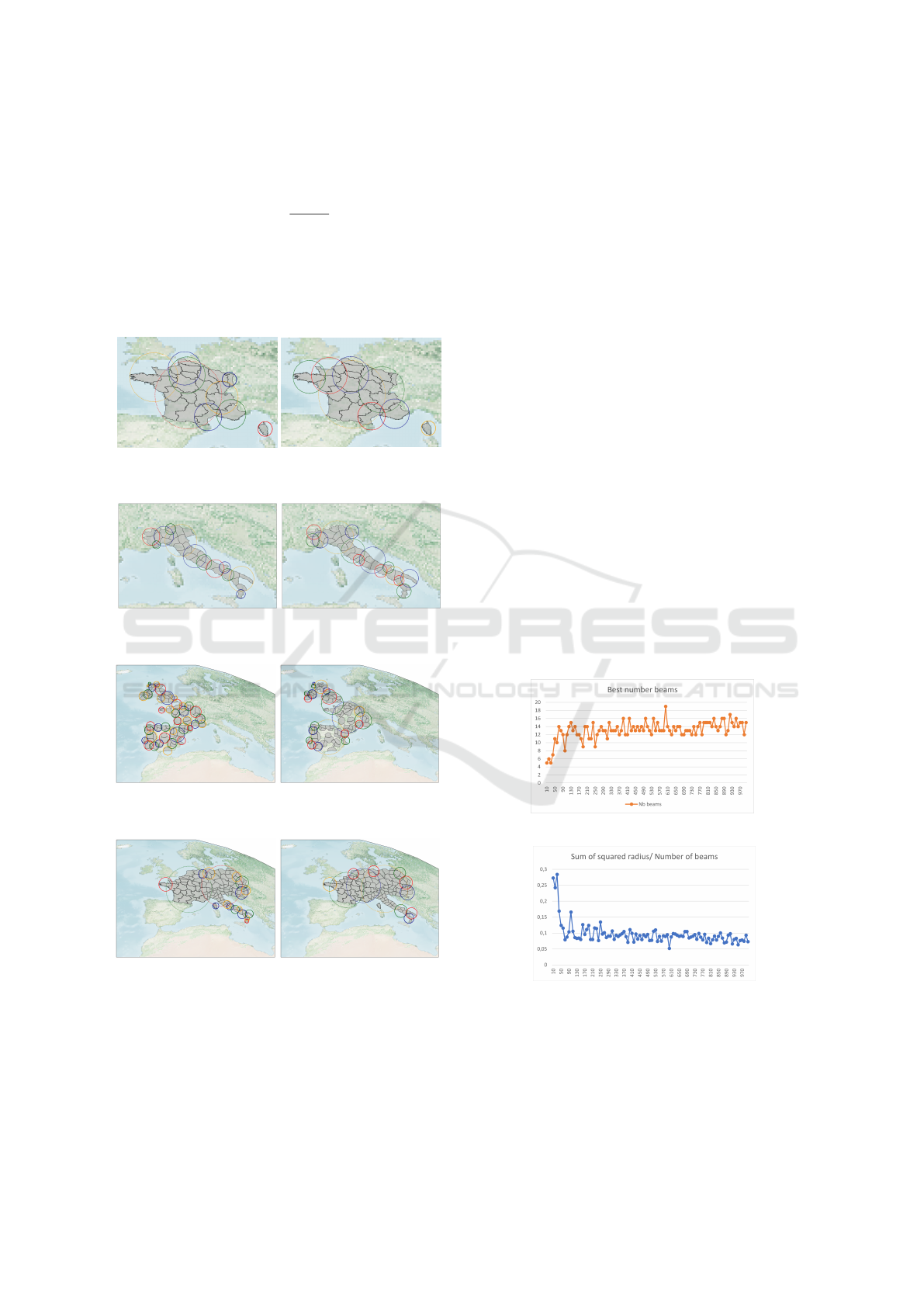
Figure 5: Matheuristic result
on France.
Figure 6: Merge-and-split
heuristic on France.
Figure 7: Matheuristic result
on Italy.
Figure 8: Merge-and-split
heuristic on Italy.
Figure 9: Matheuristic result
on West Europe.
Figure 10: Merge-and-split
heuristic on West Europe.
Figure 11: Matheuristic re-
sult on Central Europe.
Figure 12: Merge-and-split
heuristic on Central Europe.
Results of the Matheuristic. The solutions found
by the matheuristic method are illustrated in Figures
5, 7, 9, 11, depicting the best sets of beams found,
each beam being colored according to the index of
the reflector to which it is assigned. From an opera-
tional point of view, the solutions appear to be of good
quality for the telecommunication satellite designers.
The detailed results of the matheuristic are given in
Table 2. In this table, we indicate the time limits of
the matheuristic method and the time limits specified
for the call to the ILP solver at each iteration (col-
umn ILP time limit). This parameter is set manually
following preliminary experiments. It is also worth
noting that the matheuristic method manages to find
good solutions on all instances, but can have a long
computational time on the instance containing more
than 100 polygons, where the time limit is increased
to 1000 seconds.
Results of the Merge-and-Split Heuristic. Exam-
ples of solutions found by the merge-and-split heuris-
tic are given in Figures 6, 8, 10, 12. The detailed re-
sults are given in Table 2. Even if the solutions found
cover all polygons using a number of beams that is
rather low given the number of polygons to be cov-
ered, the merge-and-split heuristic finds several fea-
sible solutions during the process. Figure 13 displays
the evolution of the best solution’s quality for the West
Europe instance. Various TimeLimit values ranging
from 10s to 1000s (in increments of 10s) are consid-
ered. The number of selected beams (Figure 13a) and
the mean squared radius sum (Figure 13b) represent
the best values obtained for each run. The results in-
dicate that the improvement of both criteria becomes
less significant as the total time limit is increased.
(a) Number of beams.
(b) Squared radius sum.
Figure 13: Impact of the time limit on the performance of
the merge-and-split heuristic (time limit on the x-axis).
Comparison Between the Two Methods. Given
the time limit to consider for each instance, the
matheuristic method outperforms the merge-and-split
ICORES 2024 - 13th International Conference on Operations Research and Enterprise Systems
300
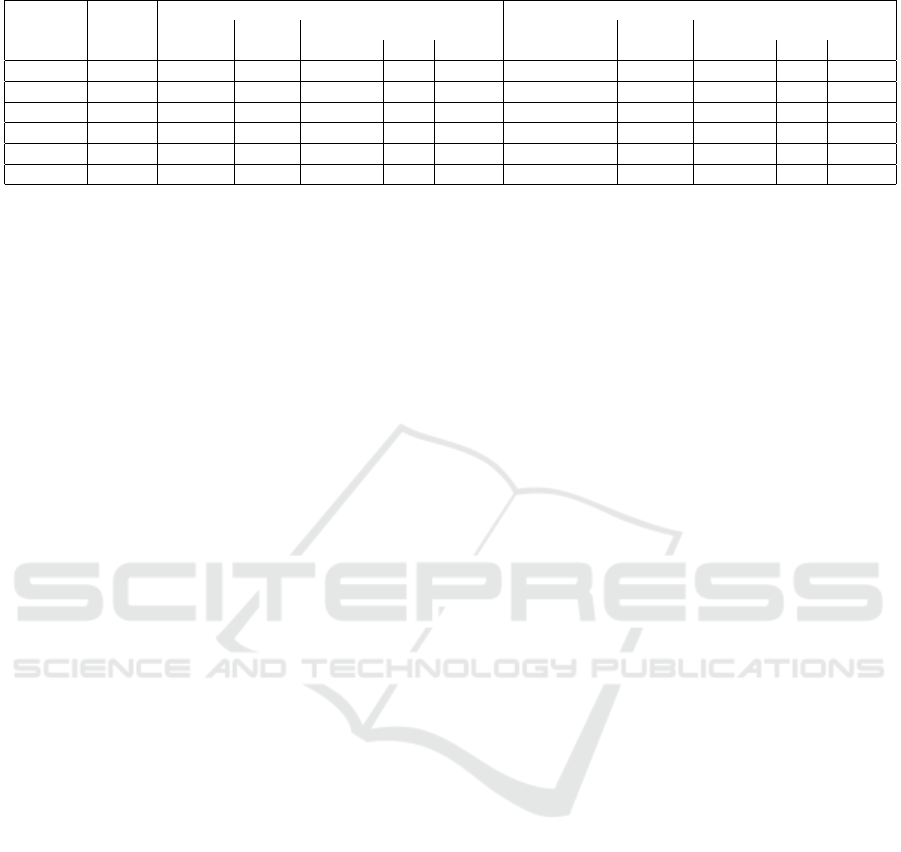
Table 2: Results of the matheuristic and the merge-and-split heuristic.
Instance
name
Time
limit
Matheuristic results Merge-and-split results
ILP time
limit
Nb
it.
Best solution
NbMergeMax Nb sol.
Best solution
|P
s
| |B
s
| MSRS |P
s
| |B
s
| MSRS
F 100 10 7 22/22 7 0.062 5 8 22/22 7 0.069
I 10 5 3 30/30 12 0.017 5 88 30/30 15 0.027
W 200 50 3 92/92 37 0.022 20 14 92/92 21 0.49
C 1000 300 7 103/103 18 0.069 50 5 103/103 12 0.12
C1 50 10 4 52/52 19 0.037 5 15 52/52 18 0.38
C2 50 10 2 51/51 6 0.13 5 1 51/51 8 0.10
heuristic in terms of number of beams selected and
mean squared radius sum, except on instance C2.
However, the merge-and-split heuristic finds several
solutions covering all polygons, while the matheuris-
tic takes a few iterations to cover all polygons. The
heuristic method considers MSRS directly, while the
matheuristic focuses on SRS, as the formulation of
MSRS is not directly linear. We can show that the
matheuristic improves the SRS criterion from itera-
tion 2 while the MSRS is improved from iteration 2
to 3 on the Central Europe instance but then increases
until the end of the process.
6 CONCLUSION
In this paper, we considered a problem associated
with the design of a telecommunication satellite used
for television broadcasting on regions, for which a set
of beams of different sizes must be defined to cover a
set of polygons, considering antenna mechanical con-
straints represented as a graph coloring problem. To
face the combinatorial issues and find solutions that
are industrially feasible, we proposed two different
methods. The first one is a matheuristic method that
is built upon an ILP formulation and uses an evolving
pool of candidate beams until finding a feasible solu-
tion. This matheuristic produces good-quality solu-
tions, but can require a long computational time. The
second method, called the merge-and-split heuristic,
iteratively constructs the beam layout by updating a
set of beams step-by-step through local merging op-
erations. This second method is faster and robust
to large scale instances. Several perspectives can be
listed for this work. For the matheuristic approach, we
could design other methods to fill the pool with rele-
vant beams, and some unused beams could be deleted
to alleviate the ILP model. Moreover, to handle
the mean squared radius sum in the matheuristic in-
stead of the squared radius sum, we could use Linear-
fractional Programming. We could also try other cri-
teria, such as minimize the maximum radius or raise
the radius to higher exponents. For the merge-and-
split heuristic, we could parallelize the process to ben-
efit from all cores and other merging methods should
be looked for, in particular to better identify the rea-
sons for the non-colorability at each merging step. A
last perspective is to define a hybrid method where the
matheuristic and the merge-and-split heuristic could
share solutions or sets of relevant beams.
REFERENCES
Br
´
elaz, D. (1979). New methods to color the vertices of a
graph. Communications of the ACM, 22(4):251–256.
Biedl, T., Biniaz, A., and Lubiw, A. (2021). Minimum ply
covering of points with disks and squares. Computa-
tional Geometry, 94:101712.
Camino, J.-T. (2017). Co-optimisation charge utile satellite
et systeme t
´
el
´
ecom.
Contardo, C. and Hertz, A. (2021). An exact algorithm for
a class of geometric set-cover problems. Discrete Ap-
plied Mathematics, 300:25–35.
Fowler, R. J., Paterson, M. S., and Tanimoto, S. L. (1981).
Optimal packing and covering in the plane are np-
complete. Information processing letters, 12(3):133–
137.
Hammill, C. W. and Dishaw, K. O. (2004). Satellite beam
pattern for non-uniform population distribution. US
Patent 6,813,492.
Kyrgiazos, A., Evans, B., and P.Thompson (2013). Irregular
beam sizes and non-uniform bandwidth allocation in
hts multibeam satellite systems. In 31st AIAA Interna-
tional Communications Satellite Systems Conference
(ICSSC).
Lourenc¸o, H. R., Martin, O. C., and St
¨
utzle, T. (2003). It-
erated local search. In Handbook of metaheuristics,
pages 320–353. Springer.
Welzl, E. (2005). Smallest enclosing disks (balls and ellip-
soids). In New Results and New Trends in Computer
Science: Graz, Austria, June 20–21, 1991 Proceed-
ings, pages 359–370. Springer.
Heuristic Methods for the Antenna-Constrained Beam Layout Optimization on Multibeam Broadcasting Mission
301
