
Developing a Sequential Mask Projection Technique for Micro-Lens
Generation Using Excimer Laser Micro-Structuring
Eric Syrbe, Sebastian Buettner, Michael Pfeifer and Steffen Weissmantel
Laserinstitut Hochschule Mittweida, Technikumplatz 17, Mittweida, Germany
Keywords: Excimer Laser, Micro-Optics, Micro-Lenses, Fluorine Laser, Direct Laser Fabrication, Micro Machining.
Abstract: Fluorine laser micro-structuring enables the generation of micro-optics in glasses and other wide band gap
materials. For the generation of micro-lenses, we developed a new micro-structuring method and the
appropriate hardware. The process is based on the mask projection technique and uses a set of different
circular masks, which are placed consecutively within the laser beam. This creates a ring-shaped ablation area
with variable inner radius. By using an appropriate set of masks, it is possible to generate a surface with a
defined spherical shape. The measured radii of curvature of the structured micro-lenses are in the range of
90 μm up to 250 μm with corresponding surface roughness values to below 100 nm. The entire process and
requirements are described, and the results are presented.
1 INTRODUCTION AND STATE
OF THE ART
Current technical innovations are often based on
improved efficiency or a more compact design. The
latter case requires a miniaturization of the included
parts, which is a constant challenge for the involved
manufacturing processes. One of the driving forces
behind are the computer and communication
technologies, because data transmission via the classic
copper cable is limited in terms of transmission speed
and becomes more susceptible to electromagnetic
interference fields the greater the volume of data
transmitted per second. One solution is offered by
optical data transmission, which is insensitive to these
effects and shows a low signal attenuation, so that
signals can be transmitted over long distances with
virtually no loss or errors. The coupling of the optical
signals into progressively smaller wave guiding
structures such as mono mode fibres require micro-
optics with best possible shape accuracy and low
surface roughness. A wide range of processes was
developed to fulfil these demands. Imprinting (Moore,
Gomez, & Lek, 2016) and additive techniques
(Bückmann, Schittny, Thiel, & Kadic, 2014; Kim,
Brauer, Fakhfouri, & Boiko, 2011) are especially used
to produce polymer micro-optics. But there is still a
great need for development regarding the production of
micro-optics in glass materials and in high-quality
fused silica, e.g. for integrating optics into a wafer.
Only a few processes are still suitable for processing
this material, with the most used being lithography.
However, the latest developments are increasingly
using femtosecond (Hua, Liang, Chen, Juodkazis, &
Sun, 2022) and CO
2
lasers (Zhao et al., 2022) or a
combination of both (Sohn, Choi, Noh, Kim, & Ahsan,
2019) to achieve the desired lens quality. The approach
we have been pursuing for some years now is to use
excimer lasers and the mask projection technique for
this purpose. It has been successfully demonstrated that
a wide variety of micro-optics can be produced using
the numerous structuring methods we have developed.
But as with the other laser structuring methods the
achievable quality is still a major challenge.
In this research we aim to reduce the influence of
re-deposition of debris at the ablation area during the
patterning process. The previously developed method
uses a rotating mask where the debris is always
pushed ahead into the following ablation area. This
results in irregularities in the structure and its surface
(Buettner, Pfeifer, & Weissmantel, 2020). To solve
this problem, we have changed the strategy for lens
structuring to a full area structuring method in which
the ablation area is gradually reduced and always lies
within the previous area. Therefore, almost no debris
should be found inside the ablation area after
structuring. To achieve this gradually changing mask
geometry we used a combination of a set of circular
masks and an outer aperture.
Syrbe, E., Buettner, S., Pfeifer, M. and Weissmantel, S.
Developing a Sequential Mask Projection Technique for Micro-Lens Generation Using Excimer Laser Micro-Structuring.
DOI: 10.5220/0012377400003651
Paper published under CC license (CC BY-NC-ND 4.0)
In Proceedings of the 12th International Conference on Photonics, Optics and Laser Technology (PHOTOPTICS 2024), pages 21-27
ISBN: 978-989-758-686-6; ISSN: 2184-4364
Proceedings Copyright © 2024 by SCITEPRESS – Science and Technology Publications, Lda.
21
2 EXPERIMENTAL SETUP
2.1 Process
The used system consists of the pulsed fluorine laser
LPF 220i of Coherent Lasersystems GmbH & Co. KG
and the micro machining station EX-157. A detailed
description of the station is given in our previous
work (Buettner, Pfeifer, & Weissmantel, 2019), as the
system is identical. Due to its beam characteristics the
fluorine laser is not suited for the direct-writing
technique. Therefore, a mask projection technique is
applied. To get the laser pulse fluence H evenly
distributed over the mask area the laser beam is
homogenized. If the threshold laser pulse fluence of
the material to be structured is exceeded the
homogenization results in a uniform ablation depth.
Both the laser pulse duration and the used laser
wavelength influence the threshold laser pulse
fluence. The fluorine laser emits photons with a pulse
duration of 25 ns and a wavelength of 157 nm, which
corresponds to a photon energy of 7.9 eV. The photon
energy is of particular interest for the machining of
wide band gap materials, as the difference between
photon energy and energy band gap has a direct effect
on the processing quality. Higher photon energy, in
relation to the band gap energy of the material to be
structured, results in a better surface quality of the
treated material, due to the better absorption
conditions. On the other hand, the energy band gap
determines which optical material can be used as
mask material for the corresponding wavelength of
the laser.
As mentioned above, we targeted to realize a
whole area treatment, which requires a combination
of several masks. More precisely, the goal was to
create a ring-shaped ablation area with a variable
inner and a constant outer radius. The inner radius of
the ablation area is controlled by a set of special
circular masks. The fabrication of the masks is
described in the following subsection.
2.2 Mask Generation
As mentioned, the masks must be transparent for the
wavelength of the laser. We choose calcium fluoride
as mask substrate material, because its band gap
energy of 12.2 eV is higher than the photon energy.
Therefore, the material is transparent for the used
laser wavelength. The 50 mask substrates have a
diameter of 5 mm and a thickness of 0.5 mm. The
latter is very low, so that hardly any losses occur. To
obtain an inner boundary of the ring-shaped ablation
area, it is necessary to generate an opaque area on the
mask substrate. We used a pulsed laser deposited
tantalum coating for this purpose. The main challenge
in generating these opaque areas is to position them
very precisely on the substrate. For the generation of
micro-lenses, these areas are circles with different
radii and these circles must each be concentric to the
substrate. To solve this problem of precise
positioning, a mask holder for the coating process was
developed.
The holder consists of three metal plates, the back
plate, the sample plate, and the front plate with the
sample plate being pinched between the other two
plates. The sample plate is a 0.5 mm thick metal plate
with 56 holes of 5 mm diameter each so that the
calcium fluoride substrates fit ideally into these holes.
Other than the back plate, the front plate also got
56 holes of 4 mm diameter to expose one face of the
substrates for coating. To change the area to be
coated, an additional thin tantalum foil is placed
between the sample and the front plate. In this foil,
holes with different diameters were cut using an ultra-
short pulse laser. In the whole assembly the sample
plate, the tantalum foil and the front plate were
aligned and fixed on the back plate.
All three plates have adjusting holes for a precise
positioning using dowel pins. The adjusting holes
ensure that all coating areas are concentric regarding
the boundary of each substrate. Following, the pulsed
laser deposition coating process is applied to the
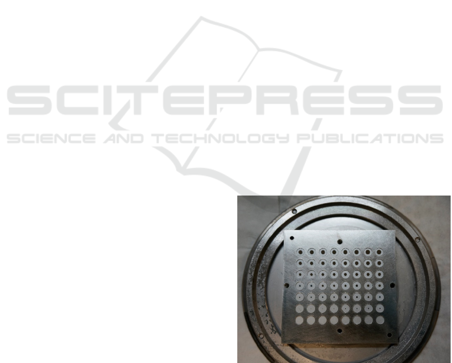
assembly. In Figure 1 the coated calcium fluoride
substrates are shown. Due to the coating mask
(tantalum foil) geometries, every area has an
individual inner radius generating ablation areas with
a radius starting from 1 μm up to 50 μm in 1 μm steps
as there are 50 different masks.
Figure 1: Coated calcium fluoride substrates on the sample
plate after the pulsed laser deposition coating process, with
the front plate and the coating mask removed.
PHOTOPTICS 2024 - 12th International Conference on Photonics, Optics and Laser Technology
22
2.3 Hardware
The sequential ablation of material with different
mask geometries requires the fast change of the
masks within the laser beam. For this a mask wheel
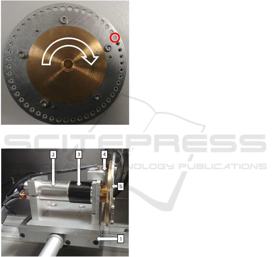
was developed, shown in Figure 2.
Figure 2: Mask wheel (red: smallest mask, white: direction
of rotation).
Figure 3: Experimental setup consisting of: linear stage (1),
stepper motor (2), 33:1 gear (3), Hall sensor (4) and mask
wheel (5).
The coated substrates are again held using three
laser-cut plates: a front and back plate with holes of
4 mm diameter and an intermediate plate with holes
of 5 mm diameter. These 4 mm holes are responsible
for the fixed outline of each micro-optic and are as
such the before mentioned constant radius aperture.
The holes in the mask wheel are placed on a circle
with a radius of 50 mm.
The mask wheel is driven by a servo motor with a
33:1 gear. The used motor encoder has a precision of
4000 increments per revolution. Furthermore, a Hall
sensor is added to reference the rotary movement
(homing). Now the center of each mask can be moved
precisely to the same position within the laser beam.
This is important for the position of the ablation areas,
and therefore for the geometry of the target structure.
The whole assembly, shown in Figure 3, is placed on
a linear stage, which is used for adjusting the wheel
position to the laser beam height.
2.4 Calculation of the Process
Parameters
In principle, two different process methods are
possible. In method 1, the mask wheel is rotated
during the structuring process at a speed that is
synchronised with the laser pulse repetition rate.
Thus, a micro-optic can be completed in about 0.25 s
if all 50 masks are used, and the laser emits at its
maximum pulse repetition frequency of 200 Hz.
However, this method requires a mask set specially
made for the micro-optics to be structured. This mask
set then enables the fast industrial production of
identical lenses.
In method 2, the rotary motion is stopped at each
mask position and the calculated number of laser
pulses needed to form the target structure is applied.
Due to the acceleration and deceleration of the mask
wheel the processing times are about one minute per
micro-optic, which is significantly slower than
method 1. On the other hand, this second method is
more flexible since a mask can be used several times
and thus more masks with different diameters fit into
the mask wheel. Since many different micro-lenses
are to be structured, the second method is used for this
study.
The number of laser pulses and the necessary set
of masks are calculated using a variance comparison.
The starting point of each calculation is the target
radius of curvature (ROC) and the given laser pulse
fluence which determines the ablation depth per laser
pulse ∆𝑧. As the lens is rotationally symmetrical the
calculation can be simplified to two dimensions. The
centre of the lens is always at a radius of r = 0 μm.
The target profile is then defined by a circle equation
with the target ROC. The calculation of the actual
profile starts with the radius value r
m,1
corresponding
to the first mask in the mask set being used. The
required ablation depth for each mask radius r
m
is the
difference between the profile depth for the current
Developing a Sequential Mask Projection Technique for Micro-Lens Generation Using Excimer Laser Micro-Structuring
23
mask radius, e.g. r
m,1
, and the profile depth for the
previous mask radius, e.g. r
m,0
. The number of laser
pulses results from the integer rounded ratio of the
necessary ablation depth to follow the target profile
and the ablation depth per laser pulse ∆𝑧. The result
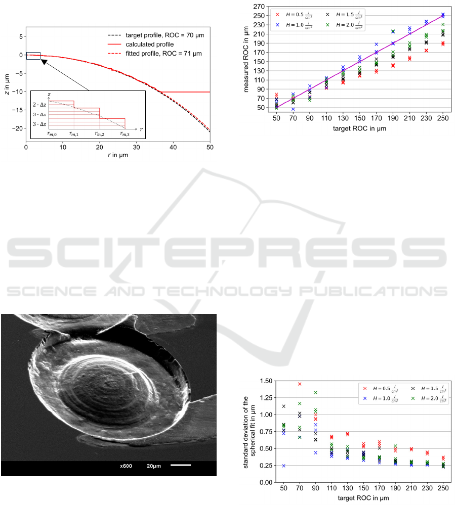
of this step-by-step calculation procedure is shown as
an example in Figure 4.
Figure 4: Exemplary result of a variance comparison
calculation for a given target profile.
3 RESULTS
We used laser pulse fluences from H = 0.5 J/cm
2
up to
2.0 J/cm
2
and target ROC from 50 μm up to 250 μm to
determine the optimal parameter set for each target
structure. In principle, the setup described in the
previous chapter enables the generation of micro-
lenses, as demonstrated by the example in Figure 5.
Figure 5: Scanning electron microscope picture of a micro-
lens with H = 1.0 J/cm
2
and a ROC of 250 μm.
After the structuring process the micro-lenses are
measured with a laser scanning microscope. The
height data is then analysed using a python program
that fits a sphere to the data with the radius as the
variable fit parameter. This radius is the measured
ROC. Each parameter set was structured three times
to evaluate the process stability. In the following
figures every point represents the result for one
micro-lens.
Figure 6: Comparison of the measured ROC to the target
ROC of the lens structures for different laser pulse fluences.
The magenta line indicates the ideal ROC.
Figure 6 shows that the measured ROC of the
structures with H = 1.0 J/cm
2
deviate the least from
the target ROC with one structure from each
parameter set almost exactly showing the target ROC.
For the other laser pulse fluences the measured ROC
is significantly smaller. The ratio between measured
and target ROC remains approximately constant for
all parameter combinations: H = 0.5 J/cm
2
: 0.75;
H = 1.5 J/cm
2
: 0.84; H = 2.0 J/cm
2
: 0.88. These
constant deviations point to an error regarding the
laser pulse fluence measurement which could be
minimised by applying a correction factor for each
laser pulse fluence. This factor can be iteratively
adjusted by structuring a series of lenses with
different target ROC and calculating the ROC
deviation.
Figure 7: Standard deviation of each spherical fitted ROC
for every structured micro-lens.
The calculation of the standard deviation for each
fitted sphere, as shown in Figure 7, can be used as an
PHOTOPTICS 2024 - 12th International Conference on Photonics, Optics and Laser Technology
24
indicator for the shape accuracy of each lens. It can be
noticed that larger target ROC values result in lower
standard deviations. The lenses structured with
H = 1.0 J/cm
2
generally show the lowest standard
deviations meaning that they correspond most closely
to the shape of an ideal sphere. The lenses with
H = 1.5 J/cm
2
and H = 2.0 J/cm
2
show values of
standard deviation that are just a bit higher. The
H = 0.5 J/cm
2
lenses generally show the highest
standard deviations. In addition to being the farthest
away from the target ROC, this laser pulse fluence is
thus not suitable for structuring useful micro-lenses.
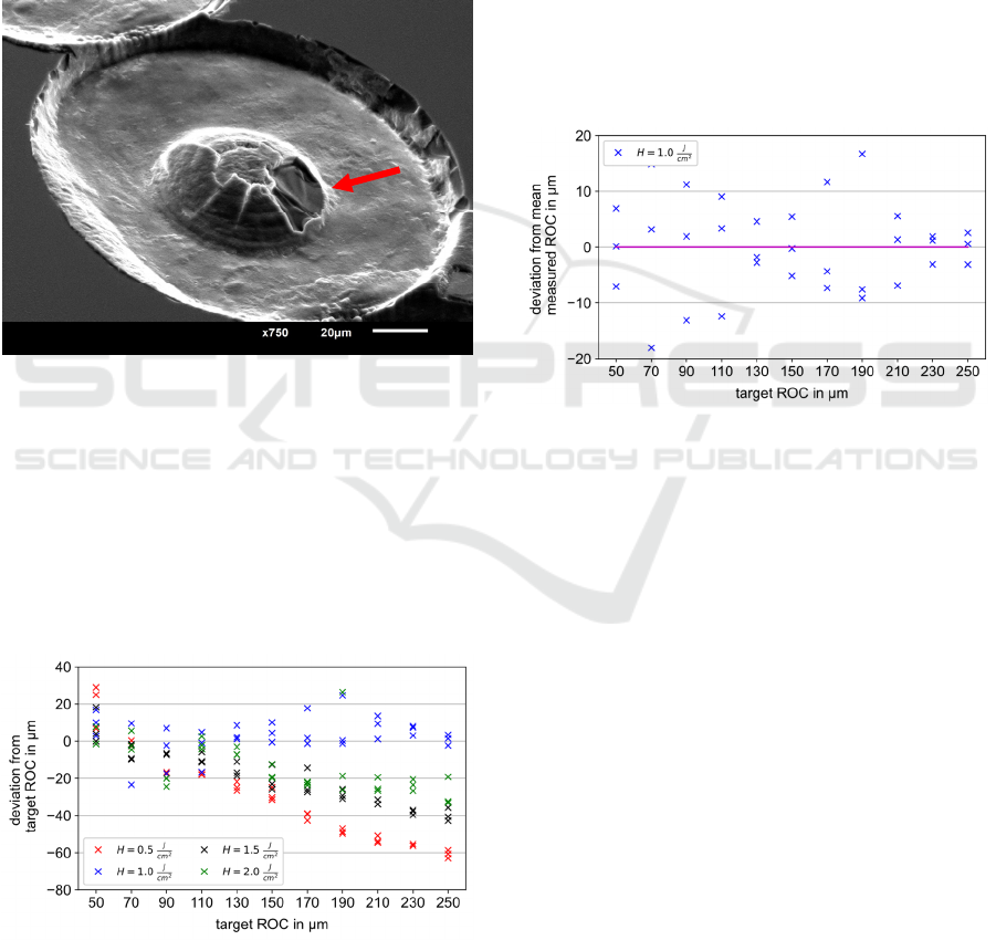
Figure 8: Scanning electron microscope picture of a micro-
lens with H = 1.0 J/cm
2
and a ROC of 50 μm. The red arrow
points at the clearly visible chipping.
Small values of target ROC result in high standard
deviations, because those lenses tend to chip making
them useless as an optical device. An exemplary
micro-lens is shown in Figure 8. The chipping is also
the reason for the measured ROC deviation for the
smallest target ROC of 50 μm and 70 μm, as shown
in Figure 9.
Figure 9: Deviation of the measured ROC from the target
ROC for different laser pulse fluences.
However, the chipping does not occur in any
micro-lens with a ROC of 90 μm and larger. This
structuring method can therefore be used to produce
micro-lenses with a radius of curvature ≥ 90 μm.
Figure 9 again shows that the laser pulse fluence of
H = 1.0 J/cm
2
is most suited for the generation of
micro-lenses closest to a given target ROC. To further
analyze these lenses regarding the repeatability of the
structuring process the deviation from the mean
measured ROC for each target ROC can be
calculated. The result is shown in Figure 10. The
lenses with a target ROC of 70 μm and 190 μm show
the largest deviation with 18 μm and 16 μm
respectively. The smallest deviation occurs with the
lenses with the largest target ROC of 230 μm and
250 μm with 3 μm each. This corresponds to a
deviation from the mean measured ROC of about 1 %
which indicates a good repeatability of the structuring
results for the respective process parameters.
Figure 10: Deviation from the mean measured ROC for
each target ROC using a laser pulse fluence of
H = 1.0 J/cm
2
. The magenta line indicates an ideal deviation
of 0 μm.
The laser pulse fluence of H = 1.0 J/cm
2
also
results in the smallest overall root mean square
surface roughness values at around S
q
= 80 nm, as
shown in Figure 11. This value is obtained by
convolving the height data with a gaussian filter using
a standard deviation value corresponding to a defined
cutoff wavelength of 𝜆
= 8 μm. Overall S
q
is
decreasing by increasing target ROC. The reason for
this is that fewer laser pulses per mask position are
required to produce micro-optics with a larger ROC.
The surface roughness for all target ROC greater than
170 μm is generally below 130 nm which in relation
to the design wavelength for optical data transmission
of 1310 nm equals 𝜆/10. The so far best shape lenses
are those structured with the laser pulse fluence of
H = 1.0 J/cm
2
. To further analyse their surface
roughness different cutoff wavelengths can be used
for the calculation, as shown in Figure 12 with
𝜆
= (2.5; 8.0; 25) μm. The smaller the cutoff value
the lesser the roughness. For the ROC of 250 μm the
three roughness values for the corresponding cutoff
Developing a Sequential Mask Projection Technique for Micro-Lens Generation Using Excimer Laser Micro-Structuring
25
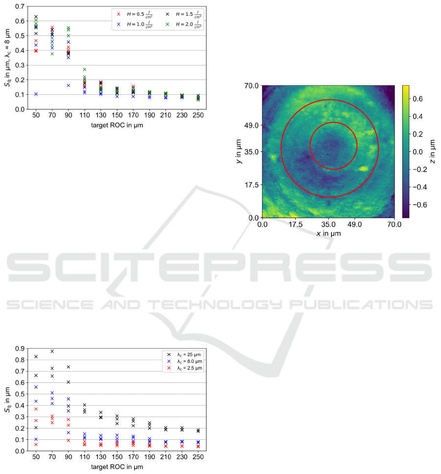
wavelengths of (2.5; 8.0; 25) μm are (38; 74; 172) nm
respectively. 38 nm is less than 𝜆/30 in relation to the
design wavelength.
Figure 11: Calculated surface roughness S
q
for every
structured lens using a cutoff wavelength of 8 μm.
Yet another way of assigning a roughness value to
each structure is already given in Figure 7 through the
standard deviation of each spherical fitted ROC.
These values can be interpreted as the roughness that
remains when the ideally fitted lens shape is
subtracted from the measured height data as the
formula for the standard deviation is identical to the
formula for surface roughness. But these roughness
values do not involve a specific cutoff wavelength,
they are rather an indication of the wavefront error a
plane wave would get when passing through the
micro-lens.
Ultimately the calculation and the needed surface
roughness value is dictated by the application the
micro-optics are used for.
Figure 12: Calculated surface roughness S
q
for all lenses
structured with a laser pulse fluence of H = 1.0 J/cm
2
using
three different cutoff wavelengths.
Regarding a process optimisation, there are two
possible starting points. Firstly, we detected a mask
misalignment error while evaluating the generated
micro-lenses, as shown exemplary in Figure 13. This
error can be a result of backlash in the motor gearbox
which could be solved by attaching the motor encoder
directly onto the mask wheel. The error could also be
caused due to misalignment during the fabrication of
the mask wheel or during the mounting of the mask
wheel to the motor axis. Both could result in the masks
not being concentric to the motor axle which would
explain the mask misalignment. Solving this problem
would lead to lenses that are closer to the ideal shape
of a sphere and simultaneously also smoother,
depending on the used roughness calculation method.
Figure 13: Mask misalignment error. The red circles
indicate the inner edge of two ablation areas that are not
ideally concentric.
Secondly, the fluorine laser slowly loses power
while not emitting at a its maximum pulse repetition
frequency of 200 Hz. As the mask wheel has to stop
at each mask position to wait until the necessary
number of laser pulses is applied, the effective pulse
repetition frequency is much lower than 200 Hz. As a
result, the laser pulse fluence slowly decreases with
increasing duration of the structuring process. This
has a particular effect on the ablation areas with the
largest inner radius because these are processed last.
Therefore, once an optimal parameter set for a
specifically needed target ROC is found, the next step
is to reduce the total process time by using only the
necessary masks and applying process method 1 as
described in section 2.4. This should further decrease
the local deviations from the ideal lens shape as the
laser can now operate close to or even at its maximum
pulse repetition frequency.
4 CONCLUSIONS AND
OUTLOOK
The combination of sequential mask projection and
fluorine laser micro-structuring enables the generation
PHOTOPTICS 2024 - 12th International Conference on Photonics, Optics and Laser Technology
26

of rotationally symmetrical micro-optics. For this
purpose, the necessary masks were produced and the
experimental setup with a rotating mask wheel was
built. Each micro-optic to be structured is defined by
the used laser pulse fluence and a structure parameter
such as the target radius of curvature of a lens
geometry. The required mask sequence and the
number of laser pulses per mask are calculated using
a variance comparison. The evaluation of the
structures produced with the calculated parameter
sets shows that the calculation method leads in
principle to the generation of micro-lenses close to
the target geometries. The measured radii of
curvature of the micro-lenses produced with a laser
pulse fluence of H = 1.0 J/cm
2
deviate the least from
the respective target radius of curvature. One
structure from each parameter set almost exactly
matches the predefined target radius of curvature. The
surface roughness S
q
of those structures decreases
with larger target radius of curvature. The smallest
calculated S
q
values are around 80 nm using the cutoff
wavelength of 𝜆
= 8 μm.
Our next studies aim to reduce the process time
per micro-optic with a different motor-gear-
combination as well as the surface roughness by
applying a laser smoothing process as an
aftertreatment.
REFERENCES
Bückmann, T., Schittny, R., Thiel, M., & Kadic, M. (2014).
On three-dimensional dilational elastic metamaterials.
New Journal of Physics, 16(3).
Buettner, S., Pfeifer, M., & Weissmantel, S. (2019).
Manufacturing of Cylindrical Micro Lenses and Micro
Lens Arrays in Fused Silica and Borosilicate Glass
using F2-Laser Microstructuring. In M. Raposo, P. A.
Ribeiro, & D. Andrews (Eds.), PHOTOPTICS 2019
(pp. 66–72). Setúbal, Portugal: SCITEPRESS - Science
and Technology Publications Lda.
Buettner, S., Pfeifer, M., & Weissmantel, S. (2020).
Fabrication of Micro Spiral Phase Plates in Fused Silica
using F2-Laser Microstructuring. In P. Albella (Ed.),
PHOTOPTICS 2020 (pp. 114–121). Setúbal:
SCITEPRESS - Science and Technology Publications
Lda.
Hua, J.-G., Liang, S.-Y., Chen, Q.-D., Juodkazis, S., & Sun,
H.-B. (2022). Free ‐ Form Micro ‐ Optics Out of
Crystals: Femtosecond Laser 3D Sculpturing.
Advanced Functional Materials, 32(26).
Kim, J. Y., Brauer, N. B., Fakhfouri, V., & Boiko, D. L.
(2011). Hybrid polymer microlens arrays with high
numerical apertures fabricated using simple ink-jet
printing technique. Optical Materials Express, 1(2),
259.
Moore, S., Gomez, J., & Lek, D. (2016). Experimental
study of polymer microlens fabrication using partial-
filling hot embossing technique. Microelectronic
Engineering, 162, 57–62.
Sohn, I.-B., Choi, H.-K., Noh, Y.-C., Kim, J., & Ahsan, M.
S. (2019). Laser assisted fabrication of micro-lens array
and characterization of their beam shaping property.
Applied Surface Science, 479, 375–385.
Zhao, L., Cheng, J., Yin, Z., Yang, H., Liu, Q., Tan, C., et
al. (2022). Rapid CO 2 laser processing technique for
fabrication of micro-optics and micro-structures on
fused silica materials. Proceedings of the Institution of
Mechanical Engineers, Part B: Journal of Engineering
Manufacture, 236(1-2), 100–110.
Developing a Sequential Mask Projection Technique for Micro-Lens Generation Using Excimer Laser Micro-Structuring
27
