
Optical Characterization of Micro Spiral Phase Plates
Sebastian Buettner, Erik Thieme and Steffen Weissmantel
Laserinstitut Hochschule Mittweida, University of Applied Sciences Mittweida,
Technikumplatz 17, 06948 Mittweida, Germany
Keywords: Fluorine Laser, Fused Silica, Micro Structuring, Orbital Angular Momentum, Spiral Phase Plates.
Abstract: The results of our investigations on laser fabricated micro spiral phase plates in fused silica are presented.
Other than in previous investigations we focussed on the optical characterization of the SPPs. As we could
show, the laser-based process enables the generation of spiral phase plates with different topological charges,
handedness, modulation depths and level numbers. Each geometric property influences the property of a
transmitting electro-magnetic field and therefore the orbital angular momentum. For the optical
characterization we observed and analysed the diffraction images of the generated SPPs. Moreover, we
validated our results by calculating the diffraction patterns under variation of certain parameters.
1 INTRODUCTION
Since Maxwell light is understood in terms of
electromagnetic fields. The connection of magnetic
and electrical fields led to a new view to photons and
light in general. The solution of Maxwell’s equations
in absence of matter and charges is an
electromagnetic wave with the properties,
wavelength, polarization, amplitude and phase. All
these are used in modern technologies and can be
influenced for different purposes and applications. In
1909 Poynting showed, that electromagnetic fields
can have spin angular momentum (SAM), which is
associated with the circular polarization of an
electromagnetic field (Poynting, 1909). In 1992 Allen
et. al. proved that Laguerre-gaussian laser modes also
got orbital angular momentum (OAM) (Allen et al.,
1992). The recognition that light can have angular
momentum led to a new understanding and
consequently to many new applications. The total
angular momentum
𝐽
⃗
of an electro-magnetic field can
be calculated from the electrical field strength
distribution 𝐸.
𝐽
⃗
=
𝜖
2𝑖𝜔
𝐸
∗
(𝑟⃗×∇)
,,
𝐸
𝑑
𝑟
⃗
(1)
+
𝐸
∗
×𝐸 𝑑
𝑟
⃗
As can be seen from equation (1), the SAM is an
intrinsic property, whereas the OAM results from a
spatial distribution. More precisely, the OAM results
from a phase distribution with an azimuthal
dependency. The modulation of an even wave front
with a helical phase term gives the Poynting vector a
helical trajectory (Allen and Padgett, 2011). The idea
that the total OAM results from the spatial
distribution is correct with respect to the entire field.
Counterintuitively, it can be shown that single
photons can also have orbital angular momentum. In
2005 Anton Zeilinger's group showed that the OAM
states of individual photons can be entangled (Mair et
al., 2001). The entanglement of OAM states of single
photons enables the development of new quantum
technologies with enormous potential (Fickler et al.,
2012,2014; Cardano et al.,2015; Krenn et al., 2017).
Moreover, the OAM become interesting for
several other applications like optical tweezers and
particle manipulation (Grier,2003). However, this
property can be used to encode classical information
for optical data transfer. In the last years, several
methods for creating light and in particular laser
beams with a defined OAM were developed. As
example, there are some micro-optical elements
which can be used to modulate and convert light. One
of them is a q-plate, which converts SAM to OAM
(Marrucci et al., 2006; Karim et al., 2009). But also
phase elements like fork gratings (FGs) and spiral
phase plates (SPPs) can be used to influence the OAM
of electromagnetic waves, as well as spatial light
modulators (SLM) (Zhu et al., 2018; Xie et al., 2018;
Bozinivic et al. 2013). In addition to this, FGs and
Buettner, S., Thieme, E. and Weissmantel, S.
Optical Characterization of Micro Spiral Phase Plates.
DOI: 10.5220/0012376400003651
Paper published under CC license (CC BY-NC-ND 4.0)
In Proceedings of the 12th International Conference on Photonics, Optics and Laser Technology (PHOTOPTICS 2024), pages 57-64
ISBN: 978-989-758-686-6; ISSN: 2184-4364
Proceedings Copyright © 2024 by SCITEPRESS – Science and Technology Publications, Lda.
57
SLMs were used to encode data to OAM states and
vice versa. To push forward the idea of OAM based
data communication, we developed a laser-based
technique, which allows the generation of individual
micro SPPs in fused silica. In this investigation we
focused on the measurement of the optical function of
the generated SPPs.
2 SPP PROPERTIES
The OAM of an electromagnetic field is a result of the
modulated phase with an azimuthal dependency. A
description of such a modulated wave is given in
equation (2), where
𝑢
(
𝑥,𝑦,𝑧
)
represents the amplitude
and 𝑒
the phase of the field. The phase depends on
the azimuth angle 𝜑 and the topological charge 𝑙.
𝑢
(
𝑥,𝑦,𝑧
)
=𝑢
(
𝑟,𝜑,𝑧
)
=𝑢
(𝑟,𝑧) ∙𝑒
∙𝑒
(2)
The modulation can be done using SPPs, which got
an azimuthal change in thickness. Due to this, the
wave front of a transmitting even electro-magnetic
wave becomes a helical shape. For SPPs the
topological charge in general represents the number
of 2π phase jumps within the structure. Moreover, one
can show that the modulation depth also influences
the number of intertwined phase fronts in the same
way. Due to this, we defined the number of phase
jumps as a separate quantity 𝑗 , as well as the
modulation depth 𝑚 . The resulting topological
charge 𝑙 is given then by equation (3).
𝑙=𝑚∙
𝑗
(3)
This provides a certain degree of freedom regarding
the generation of the SPPs. According to the Huygens
law, the effect of 𝑗 and 𝑚 differs. Regarding to this, 𝑗
led to the interaction of the elementary waves of one
wave front. Whereas 𝑚1 led to the interaction of
the elementary waves of 𝑚 wave fronts. As result, the
modulation depth can act as time delay, due to the
delay of interaction of elementary waves of the 1
st
and
the m
th
wave front. Concluding, the modulation depth
induces a time delay from fractional to full
modulation. It is unlikely, but it could be necessary to
take this in account for some ultra-fast applications.
Due to the delay is in a range of few femtoseconds for
a typically wavelengths in the micron range. An
ideally helical modulated wave front converts a
gaussian to a ring-shaped intensity distribution. In the
centre of the SPPs is a phase singularity, which occur
also in the modulated wave front. Therefore, the
intensity in the range of the singularity approaches
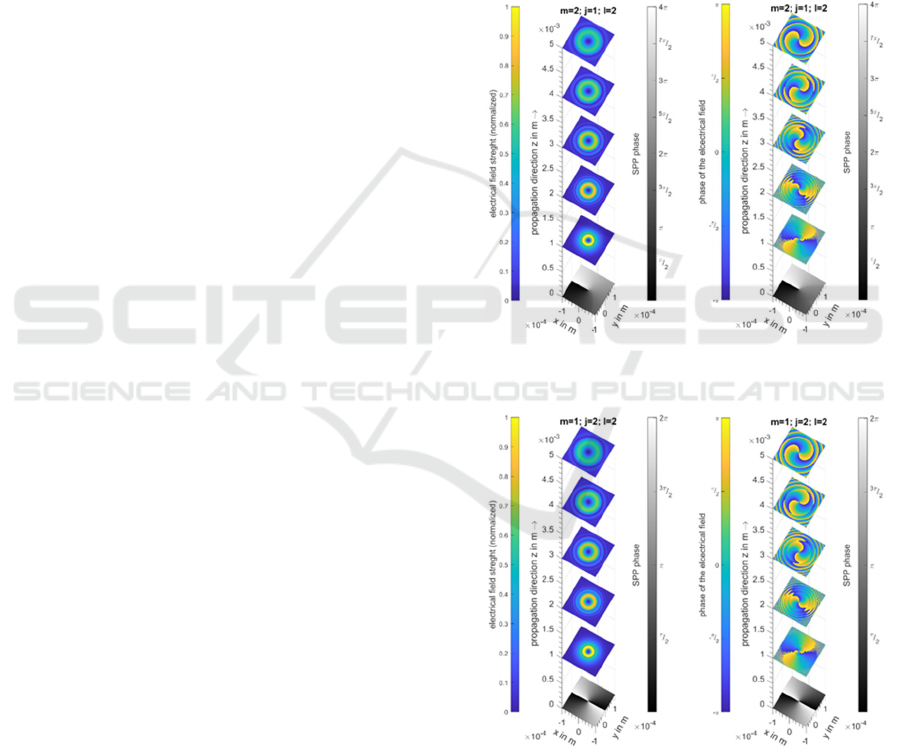
zero. In Fig. 1 and Fig. 2 the calculated electric field
and phase distributions are shown for different
distances to the plane of modulation. The calculations
were done using the Fresnel-Kirchhoff diffraction
integral. The comparison of Fig. 1 and Fig. 2 shows
that the modulation depth 𝑚 and the number of phase
jumps j got the same effect. Due to this, the
topological charge of the field can be controlled by
the modulation depth, the number of phase jumps or
both simultaneously. This is beneficial regarding to
the generation process, which allows the generation
of SPPs with at least two sectors. By stetting 𝑚 to 0.5
an SPP with a 𝑙 of 1 can be generated too.
Figure 1: Calculated electrical field strength (l.) and phase
distribution (r.) of an OAM beam (𝑙=2, 𝑗=1, 𝑚=2).
Figure 2: Calculated electrical field strength (l.) and phase
distribution (r.) of an OAM beam (𝑙=2, 𝑗=2, 𝑚=1).
Our interest in this field of research and expertise in
laser micro structuring of optical materials led us to
develop a process for micro SPP generation. The
process allows the fabrication of those elements in
various versions. For example, Fig. 3 shows one of
PHOTOPTICS 2024 - 12th International Conference on Photonics, Optics and Laser Technology
58
the generated SPPs in fused silica. A detailed
description of the experimental setup and the process
can be found in a former report (Buettner et al. 2020).
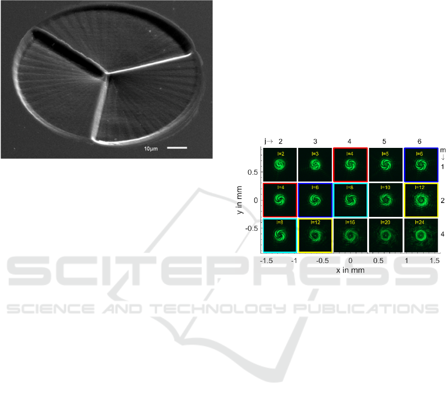
Figure 3: Scanning electron microscope image of a right-
handed micro spiral phase plate (j=3, m=2, l=6).
3 RESULTS AND DISCUSSION
For these investigations, we observe and evaluate the
diffraction images of the SPPs using the measurement
setup that we set up earlier. Due to this, a description
of the basic set-up can also be found in the above-
mentioned paper. Following, it is also briefly
described. The measurement setup consists of a
frequency-doubled Nd:YAG laser (λ=532 nm), a
series of polarisers, two lenses with different focal
lengths (f=175 mm, f=10 mm) and neutral density
(ND) filters. With the improved setup the laser spot
size can be set to a defined value. Reducing the size
of the laser spot requires a reduction in the intensity
of the measuring laser to avoid overdriving the
camera. This is achieved using two polarisers and
additional ND filters. The radius of the frequency-
doubled Nd:YAG laser beam is 0.65 mm. This is
reduced to 37 µm using the two lenses. The substrate
is positioned at the focal point of the second lens. At
this point the wavefront is assumed to be flat.
Moreover, an XY axis is used to position the SPPs
within the measurement laser beam. In this way the
SPP can be adjusted concentric to the laser beam. The
resulting diffraction images were recorded with a
confocal microscope positioned above. The whole
microscope can be moved vertically in micron steps,
which allows to adjust the distance between the SPP
and the plane of observation. This allows the
diffraction images to be recorded at different
distances from the SPPs. The diffraction images are
used to calculate the maximum and root mean square
(rms) radius (𝑟
,𝑟
) of the ring-shaped intensity
distributions too, as well as the divergence angle of
the propagating fields. For a first measurement we
used a laser spot size of 90 µm. Due to the spot size
is in the range of the SPP diameter, the modulated and
unmodulated components of the transmitting field
were interfering strongly, as can be seen in Fig. 4. The
generated interferograms show the number and
symmetry of the twisted phase fronts in the form of
curved intensity maxima. The number of maxima is
equal to the topological charge of the corresponding
SPP. Moreover, the comparison of the interferograms
of SPPs with the same topological charge shows the
same number of maxima, due to the modulation depth
and the number of phase jumps have the same effect.
Figure 4: Interferograms of the SPPs with different
topological charges, 3 mm above the modulating surface.
The alignment of the SPPs was done by observing
the symmetry of the diffraction pattern during the
adjustment. Nevertheless, some of the interferograms
show asymmetries within the intensity distribution.
These deviations result from geometric asymmetries
of the SPPs. Moreover, for SPPs with a topological
charge >12 the intensity maxima cannot be separated
easily. The higher the topological charge, the more
the intensity distribution is distorted. This can be
explained by a change of the local pitch angle within
one sector and the slope edges between the steps of
the structures. The change of the local pitch angle is
a result of a varying ablation depth per laser pulse
during the generation process and it is caused by the
fluctuation of the laser pulse energy. The slope angle
at the edges of the ablation area depends on the
ablation depth per pulse. Due to this, the edges of the
steps got a constant slope angle, which depends on the
ablation depth and therefore the laser pulse fluence.
The local pitch angle of the SPP sector is given by the
topological charge, the modulation depth and the
distance to the optical axis. Consequently, the slope
angle of the step edges mostly does not match the
Optical Characterization of Micro Spiral Phase Plates
59
required local pitch angle of the SPP sector.
Increasing the modulation depth by the step number
increases the slope area within one sector. These areas
contain a different phase information and do not
contribute to the targeted phase and intensity
distribution. The slope edges got a negative effect on
the resulting wave front and increase the losses and
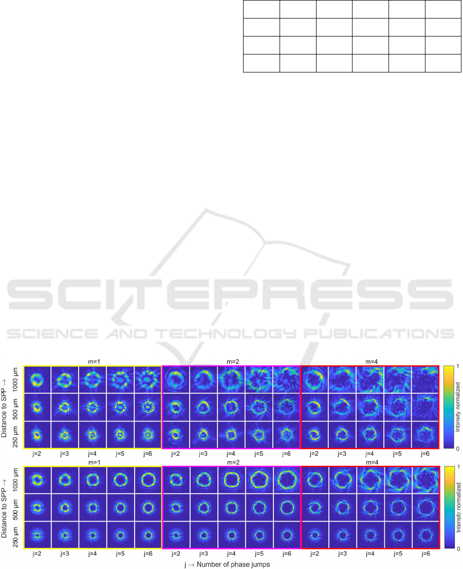
distortion within the diffraction image. Furthermore,
we observed the diffraction images with a beam
radius of 𝑤
= 37 µ𝑚 (Fig. 5). For the SPPs with a
modulation depth of 𝑚=4 the quality of the
diffraction images was very low and affected by
distortion. In general, the diffraction pattern does not
show the expected ring-shaped intensity distributions
as shown in Fig. 1 and Fig 2. Instead, the images show
intensity maxima, which are surrounded by a ring-
shaped distribution with lower intensity. The reason
for this is an insufficient phase modulation, due to the
total depth of the structures not matching the
equivalent
2
𝜋, 4𝜋 and 8𝜋 phase shift (Tab. 1). This
also can be shown by the numerical calculations of
the diffraction images considering the deviations
from the ideal phase. The calculated diffraction
images show the same characteristics as the measured
(compare Fig. 5 (a) and (b)). Concluding, the
deviation of the ideal phase in terms of a systematic
deviation from the depth causes a change in the
intensity distribution The intensity maxima rinsing
with the increase of the deviations.
The reason for the deviations of the structure
depths is an insufficient adjustment of the laser pulse
fluence. The adjustment was done measuring the laser
Table 1: Phase shift of the SPPs, calculated from the
measured maximum structure depth.
m / j 2 3 4 5 6
1
1.65π 1.72 π 1.75 π 1.82 π 1.85 π
2
3.50 π 3.63 π 3.69 π 3.67 π 3.77 π
4
6.97 π 6.96 π 6.70 π 6.75 π 6.84 π
power near to the image plane of the laser system at a
constant frequency of 200 Hz. This is necessary
because the laser power must be raised to the
measuring range of the power meter. A constant
operation of the laser at a defined frequency led to the
thermal equilibrium of the laser tube. For the SPP
generation a pulse-on-demand operation is necessary.
In this mode, the effective laser pulse frequency is in
a range of 1 Hz, due to the slow angular velocity of
the rotation stages. By changing the operation mode
and therefore the laser frequency, the laser is not in a
thermal equilibrium anymore and the laser power
drops. As result, we reached only 88.5 ± 3.28 % of
the targeted depth. This systematic deviation can be
avoided improving the measurement for the pulse-on-
demand mode or using a power offset.
However, we calculated the diffraction images for
the ideal SPPs with
2
𝜋, 4𝜋 and 8𝜋 phase shift (Fig.
7). The calculation was done using a continuous
phase profile. The aperture was set to 150 µm and is
therefore twice as large as the beam diameter. This
reduces the influence of the aperture on the
diffraction image.
Figure 5: Coloured representation of the measured diffraction images (generated by the SPPs) (a) and the calculated (b)
intensity distributions for the appropriate distances (𝑧 = 250 µ𝑚, 500 µ𝑚, 1000 µ𝑚 / 𝑤
= 37µ𝑚 / 𝜆 = 532 𝑛𝑚).
(a)
(b)
PHOTOPTICS 2024 - 12th International Conference on Photonics, Optics and Laser Technology
60
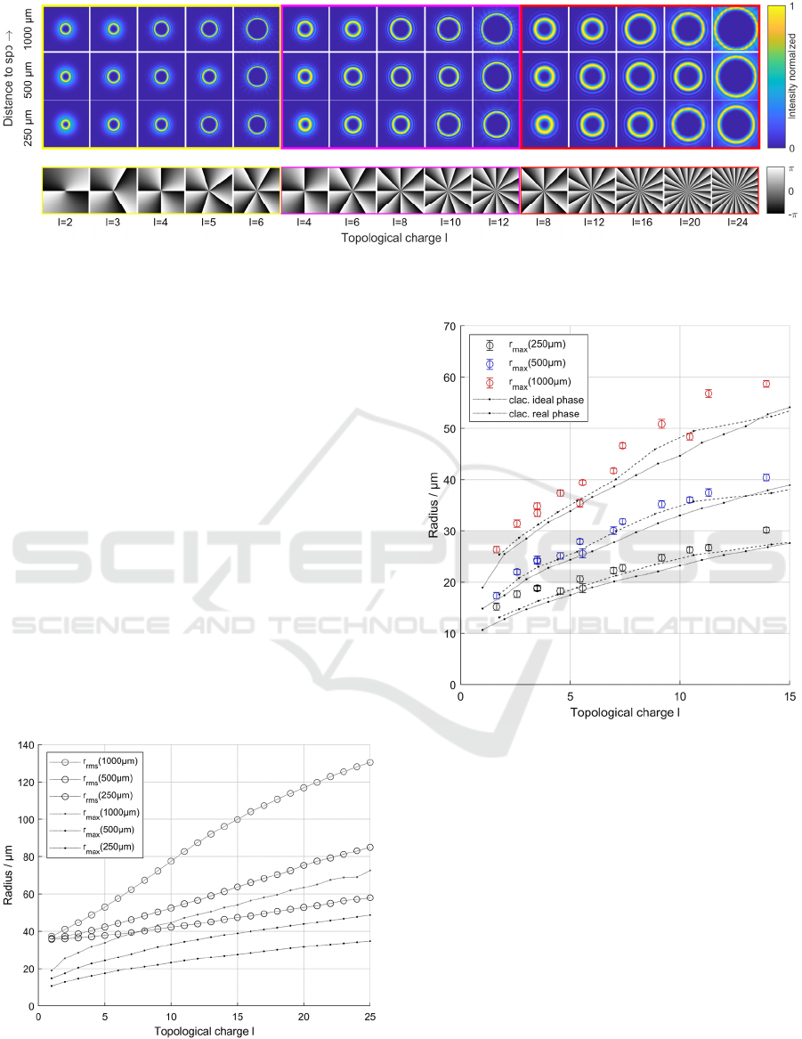
Figure 6: Coloured representation of the calculated intensity distributions (top) using an ideal and continuous phase
distributions (bottom) in a distance of 250 µ𝑚, 500 µ𝑚 and 1000 µ𝑚 to the modulation plane.
Moreover, the size of the target area is changed with
the distance, due to the divergence of the field and
appropriate increase of the radius of the distribution.
The calculation of the ideal diffraction images shows
the dependency of the rms and maximum beam radius
from the topological charge without the influence of
the aperture and steps. The topological charge was
varied from 1 to 25 and the modulation depth was set
to 𝑚=1 for all calculations. According to the target
values of the generated SPPs the optimum diffraction
images are shown in Fig. 6. The maximum radii 𝑟
,
were calculated from the 1000 biggest intensity
values, using a circular fit function. The rms radius
𝑟
was calculated by the second moment method.
As can be seen, both, the rms and the maximum radius
increases with the topological charge (Fig. 7.). For
small values of the topological charge the maximum
and the rms radius depend on 𝑙 in a very different
way. With higher values the course of both radii
become more linear.
Figure 7: Root mean square (rms) and maximum radii of
the calculated ideal intensity distributions depending on the
topological charge for different distances z.
Figure 8: Radii 𝑟
of the measured and calculated
intensity distribution for different distances in propagation
direction. The calculation was done using the ideal phase
and determined values for the real SPPs (see Tab. 1).
It can be seen further that the rms radii for 𝑙=1 is
close to the radius of the input beam waist 𝑤
. The
measured maximum radii basically follow the course
of the calculated maximum radii (Fig. 8). However,
there is a small offset of the measured radii to the
calculated, which can be partially explained by the
inaccuracy of the phase of the generated SPPs. Taking
this into account, the calculated radii approach the
measured radii, but a small difference remains. The
reason for this could be a slight misalignment of the
SPPs in the direction of propagation. Therefore, the
wavefront of the measuring beam is not flat, which
increases the radii of the intensity distributions and
the divergence of the fields.
Optical Characterization of Micro Spiral Phase Plates
61
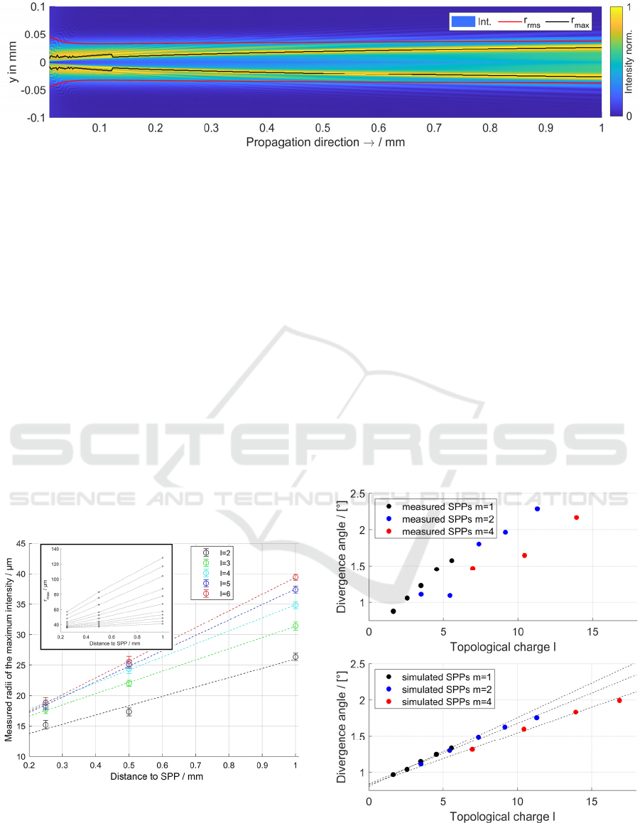
Figure 9: Calculated intensity distribution of an OAM beam (𝑙=2) along the direction of propagation.
For future investigations, the wavefront of the
measuring system must be characterized using a wave
front sensor. The rms and maximum radii were also
compared to theoretical values. Therefore, Padgett
and colleagues derived equations for the maximum
and rms radius for two different kinds of OAM beams
(Padgett et al., 2015). They distinguish between
modes with a fixed beam waist (e.g. converting
Hermite-Gauss modes into Laguerre-Gauss using a
cylindrical lens mode converter) and modulated
gaussian modes, which can be generated by
illuminating a fork grating. Depending on the mode,
a transmitting field propagates differently. Therefore,
the far field beam divergence scales either with the
square root or linear with the topological charge. Due
to the generation of our OAM beams using SPPs, we
expect that the beam radius and the divergence
depends on the topological charge either in the one or
the other way. But it must be taken in account that our
measurements and calculations were done somewhat
between the near and the far field.
Figure 10: Measured and calculated radii 𝑟
of the
intensity distributions depending on the distances in
propagation direction 𝑧.
The equations given by Padgett et al. are valid for the
far field. Moreover, the relation between the size and
feature size of our generated SPPs and the wavelength
got a significant influence on the propagation of the
OAM beams, due to the propagation is not transversal
at all. This can lead to an abrupt change of the radius
of maximum intensity along the propagation axis (see
𝑟
in Fig. 9). Due to this, the measured results are
valid for these specific structures of this specific size
and the mentioned conditions. But the radii do not
match the values calculated from the equations, due
to the given reason. Fig. 10 shows the measured 𝑟
as a function of the distance to plane of modulation
for OAM beams with different topological charge.
The data fits very well with a linear progression.
However, as can be seen from the calculated data, the
curve is generally not linear and it also differs
depending on the topological charge. Here,
investigations with a more precise analysis of the
divergence are necessary.
Figure 11: Divergence angle depending on the topological
charge calculated from of the measured intensity
distributions (top) and the calculated intensity distributions
(bottom).
PHOTOPTICS 2024 - 12th International Conference on Photonics, Optics and Laser Technology
62

Nevertheless, we calculated the average divergence
angle for the measured and calculated intensity
distributions (Fig 11.). Both, the measured and
calculated angles show a nearly linear dependency
regarding to the topological charge. Moreover, the
data points are grouped by modulation depth m and
the progression between the points of the groups is
discontinuous. In addition, each group show a
different slope depending on the modulation depth.
This shows the influence of the modulation depth on
the divergence of the propagating fields, and it must
be considered for the design of micro SPPs for a
specific application. Concluding, the propagating
fields diverge differently depending on the
topological charge. In addition to this, the modulation
depth also got an influence on the divergence angle.
In order to find a general rule for the radii and the
divergence of the OAM beams as a function of the
topological charge, the further generation and
analysis of a large number of high-quality SPPs is
necessary. In further investigations, also the influence
of the relationship between feature size and design
wavelength should be analysed in more detail.
4 CONCLUSIONS
We show the results of our investigations on the
optical characterization of laser fabricated micro
SPPs. Therefore, we used two measurement
configurations. The measured results were verified by
numerical calculations of the diffraction images using
the Fresnel-Kirchhoff diffraction integral. The
captured interferograms show the equality of the
modulation depth and number of phase jumps, which
act on the topological charge in the same way.
Moreover, we captured the diffraction images with a
reduced beam radius to supress the interference
between the modulated and unmodulated proportion
of the propagating field. It could be shown that the
calculation in consideration of the geometric
properties led to equal diffraction pattern compared to
the measured one. This enables us to identify
irregularities and asymmetries within the structures
and their optical effect.
Simultaneous, we calculated the diffraction
images for ideal spiral phase distributions to
determine the course of the ideal maximum and root
mean square radius of the ring-shaped intensity
distributions. The comparison of the maximum radii
shows a good fit in course but a small offset of the
measured values, due to a small misalignment of the
SPPs. Moreover, we determined the divergence
angles of the OAM beams, as well as the influence of
the topological charge on their divergence.
Surprisingly, the modulation depth also got an
influence on the divergence of the propagating fields.
However, it must be considered that the
measurements and calculations were carried out on
micro-optics with feature sizes close to the
wavelength range. Moreover, the range of
measurement is somewhat between the near and far
field. Due to this, the far field approximation is not
valid. In further investigations, the region of interest
therefore should be increased. This may connect our
experimental data to the far field approximation.
Finally, the generation process and quality of the
micro spiral phase plates must be improved. In
particular, the precise control of the laser pulse energy
and therefor the ablation depth per pulse can raise the
quality of the SPPs significantly. As we have shown,
the depth of the structures was not exactly equal to the
required equivalent targeted phase shift and the slopes
and edges within the structure increased the distortion
within the diffraction image. Regarding to this, we
currently work on an improved process which will
allow us to generate continuous surfaces with
arbitrary geometry with highest possible quality.
AKNOWLEDGEMENTS
The authors would like to thank the referees for their
careful reading the manuscript and their valuable
comments and suggestions. Furthermore, we
thankfully acknowledge the financial support from
the free state of saxony.
REFERENCES
Poynting, J. H. (1909): The Wave Motion of a Revolving
Shaft, and a Suggestion as to the angular momentum in
a Beam of Circular Polarized Light.
Allen, L.; Beijersbergen, M. W.; Spreeuw, R. J. C.;
Woerdman, J. P. (1992). Orbital angular momentum of
light and the transformation of Laguerre-Gaussian laser
modes. In: Physical Review A, 45(11), S. 8185-8189.
Allen, L. and Padget, M. (2011). The Orbital angular
momentum of light. In Twisted Photons, WILEY-VCH
Verlag GmbH, pp. 1-12, Weinheim.
Mair A.; Vaziri, A.; Weihs, G.; Zeilinger, A. (2001).
Entanglement of the orbital angular momentum states
of photons. In: Nature, 412, pp. 313-316.
Fickler, R.; Lapkiewicz, R.; Plick, W. N.; Krenn, M.;
Schaeff, C.; Ramelow, S.; Zeilinger, A. (2012).
Quantum Entanglement of High Angular Momenta.
Science, 338(6107), 640–643. doi:10.1126/science.12
27193
Optical Characterization of Micro Spiral Phase Plates
63

Fickler, R.; Lapkiewicz, R.; Huber, M.; Lavery, M. P.J.;
Padgett, M.J.; Zeilinger, A. (2014). Interface between
path and orbital angular momentum entanglement for
high-dimensional photonic quantum information.
Nature Communications, 5:4502., pp. 1-6.
Cardano, F.; Massa, F.; Qassim, H.; Karimi, E.;
Slussarenko, S.; Paparo, D.; de Lisio, C.; Sciarrino, F.;
Santamato, E.; Boyd, R. W.; Marrucci, L. (2015).
Quantum walks and wavepacket dynamics on a lattice
with twisted photons. Science Advances, 1(2),
e1500087–.
Krenn, M.; Malik, M.; Erhard, M.; Zeilinger, A. (2017).
Orbital angular momentum of photons and the
entanglement of Laguerre–Gaussian modes.
Philosophical Transactions of the Royal Society A:
Mathematical, Physical and Engineering Sciences,
375(2087).
Grier, D. A revolution in optical manipulation (2003).
Nature 424, pp. 810–816.
Marrucci, L.; Manzo, C.; Paparo, D. (2006). Optical Spin-
to-Orbital Angular Momentum Conversion in
Inhomogeneous Anisotropic Media. Physical Review
Letters, 96(16), pp. 163905–.
Karimi, E.; Piccirillo, B.; Nagali, E.; Marrucci, L.;
Santamato, E. (2009). Efficient generation and sorting
of orbital angular momentum eigenmodes of light by
thermally tuned q-plates. Applied Physics Letters,
94(23), pp. 231124–.
Zhu, L.; Wang, A.; Chen, S.; Liu, J. and Wang, J. (2018):
Orbital angular momentum mode multiplexed
transmission in heterogeneous few-mode and multi-
mode fiber network; In: Opt. Lett. 43, p. 1894-1897.
Xie, Z.; Gao, S.; Lei, T.; Feng, S.; Zhang, Y.; Li, F.; Zhang,
J.; Li, Z.; Yuan, X. (2018). Integrated (de)multiplexer
for orbital angular momentum fiber communication. In:
Photonics Research, 6(7), pp. 743-749.
Bozinivic, N.; Yue, Y.; Ren, Y.; Tur, M.; Kristensen, P.;
Huang, H.; Willner, A.E.; Ramachandran, S. (2013).
Terrabit-Scale Orbital Angular Momentum Mode
Division Multiplexing in Fibers. In: Science,
340(6140), pp. 1545-1548.
Buettner, S., Pfeifer, M., Weissmantel, S., (2020):
Fabrication of Micro Spiral Phase Plates in Fused Silica
using F2-Laser Microstructuring, 8th International
Conference on Photonics, Optics and Laser
Technology.
Padgett, M. J; Miatto, F. M.; Lavery, M. P. J.; Zeilinger, A.;
Boyd, R. W. (2015). Divergence of an orbital-angular-
momentum-carrying beam upon propagation. New
Journal of Physics, 17(2), 023011–. doi:10.1088/1367-
2630/17/2/023011
PHOTOPTICS 2024 - 12th International Conference on Photonics, Optics and Laser Technology
64
