
Robust 3D Point Cloud Registration Exploiting Unique LiDAR Scanning
Pattern
Ahmad Kamal Aijazi
a
and Paul Checchin
b
Institut Pascal, UMR 6602 CNRS Universit
´
e Clermont Auvergne, F-63000 Clermont-Ferrand, France
Keywords:
LiDAR, Non-Repetitive Scanning, 3D Point Cloud and Scan Registration.
Abstract:
The task of 3D point cloud registration is fundamentally about aligning multiple scans or point clouds ob-
tained from one or more LiDAR sensors to create a unified and accurate representation of the scanned scene.
This process serves as the cornerstone for applications such as map building, autonomous navigation, land
surveying and many others. While 3D registration techniques have made significant advancements, several
persistent challenges continue to warrant research attention and innovation. Recently, non-repetitive scanning
LiDAR sensors are emerging as a promising alternative for 3D data acquisition. In this paper, a novel 3D
point cloud registration method is presented that exploits the unique scanning pattern of the sensor to register
successive 3D scans. The sensor is first characterized and then, using the characteristic equation of the unique
scanning pattern, a perfect scan is reconstructed at the target distance. The real scan is then compared with this
reconstructed scan to extract objects in the scene. The displacements of these extracted objects in successive
scans, with respect to the center of the unique scanning pattern, are compared in successive scans to determine
the transformations that are then used to register the successive scans. The proposed method is evaluated on
two real and different datasets and compared with other state-of-the-art registration methods. The results show
that the method is comparable with other methods in terms of accuracy but surpasses them in performance in
terms of processing time.
1 INTRODUCTION
The advancement of LiDAR (Light Detection and
Ranging) technology has played a pivotal role in rev-
olutionizing our ability to capture three-dimensional
representations of the environment with unprece-
dented accuracies and details. The task of 3D point
cloud registration is fundamentally about aligning
multiple scans or point clouds obtained from one
or more of these LiDAR sensors to create a uni-
fied and accurate representation of the scanned scene.
However, the process of registering multiple LiDAR-
generated point clouds into a single, coherent 3D
model is not without its challenges.
Most of the state-of-the-art methods employ repet-
itive scanning LiDAR sensors which have their inher-
ent limitations. Recently, non-repetitive scanning Li-
DAR sensors are emerging as a promising alternative
for 3D data acquisition. In this paper, we explore the
use of such a LiDAR sensor to improve the 3D point
a
https://orcid.org/0009-0000-6349-128X
b
https://orcid.org/0000-0002-2930-3393
cloud registration process using its unique scanning
pattern.
2 RELATED WORK
Point cloud registration is an important task for lo-
calization and mapping applications. In this section,
we review some key research in the field of 3D point
cloud registration.
The Iterative Closest Point algorithm (ICP) pro-
posed by Besl and McKay (1992) has been an ele-
mentary method in point cloud registration. In this
method, the distance between corresponding points
in two point clouds is iteratively minimized, allowing
for rigid transformation estimation. Extensions, such
as the Generalized ICP (GICP) by Segal et al. (2009),
dense normal based ICP (NICP) (Serafin and Grisetti,
2015) and Sample Consensus ICP (Xie et al., 2022)
have improved robustness to various scenarios.
Tazir et al. (2018) modified the method for select-
ing 3D points for the matching process in the standard
ICP algorithm to propose Cluster Iterative Closest
Aijazi, A. and Checchin, P.
Robust 3D Point Cloud Registration Exploiting Unique LiDAR Scanning Pattern.
DOI: 10.5220/0012342600003654
Paper published under CC license (CC BY-NC-ND 4.0)
In Proceedings of the 13th International Conference on Pattern Recognition Applications and Methods (ICPRAM 2024), pages 679-686
ISBN: 978-989-758-684-2; ISSN: 2184-4313
Proceedings Copyright © 2024 by SCITEPRESS – Science and Technology Publications, Lda.
679

Point (CICP) that successfully register point clouds
of different densities obtained form different sensors.
Another variant Global ICP (G-ICP) presented by Ai-
jazi et al. (2019) employs bundle adjustment to fine
tune the registration process, at the end, in addition
to the scan by scan registration using point to plane
matching. However, such method is not suitable for
real-time processing.
Feature-based registration methods focus on ex-
tracting distinctive features from point clouds and
matching them to establish correspondences. The
SIFT-based approach by Rusu et al. (2009) and the
Fast Point Feature Histograms (FPFH) by Rusu and
Cousins (2011) are notable examples.
One of the important concerns for point cloud
registration is scalability. The LeGO-LOAM system
by Xue et al. (2022) offers a real-time solution for
large-scale point cloud registration and mapping. Re-
cent advances in deep learning have led to the emer-
gence of deep neural networks for point cloud regis-
tration (Pais et al., 2019; Choy et al., 2020).
Some works have also employed recently devel-
oped non-repetitive scanning LiDARs. The work has
also been done to register their point clouds. An ex-
tension of classical feature-based methods, the work
by Wang et al. (2021) introduced a feature-based reg-
istration algorithm employing point clouds generated
by non-repetitive scanning LiDARs leveraging dis-
tinct features to establish correspondences. Wang
et al. (2023) proposed a novel method that leverages
deep learning techniques for sparse point cloud reg-
istration, achieving impressive results in various sce-
narios. He et al. (2021) introduced a highly efficient
algorithm designed for non-repetitive scanning Li-
DARs, combining geometric and learning-based ap-
proaches to improve speed and accuracy. Li et al.
(2023) presented a registration method for combin-
ing non-repetitive scanning LiDAR point clouds with
RGB-D data, enabling precise 3D scene reconstruc-
tion. Zou et al. (2023) presented a plane-based global
registration (PGR) approach for coarse registration
followed by an ICP algorithm to register point clouds.
In this paper, we present a fast 3D scan registra-
tion method exploiting the unique scanning pattern of
a LiDAR sensor. To the best of our knowledge, no
work has so far exploited the non-repetitive scanning
pattern to register point clouds.
In the following sections, we first explain the Li-
DAR sensor and its characterization (Section 3) and
then our method (Section 4). The experiments and re-
sults are presented in Section 5 while we conclude in
Section 6.
3 CHARACTERIZATION OF
NON-REPETITIVE SCANNING
LIDAR
The recently developed Mid-70 sensor by LIVOX is
a solid state 3D LiDAR. The sensor is capable of
collecting up to 100 000 points per second within a
circular field of view directly in front of the scan-
ner’s glass window. With a small form factor, it
has a range of about 260m with precision of up to
0.02m (see Table 1 for more specifications). How-
ever, what really sets this sensor apart from other laser
scanners is its scanning mechanism. Rather than ro-
tate the laser scanner/receiver pair themselves (as is
done in a multi-line scanner like Velodyne LiDARs),
this holds the two in a “solid state”, immobilized in-
side the scanner’s housing while the outbound and
inbound light is directed through a pair of Risley
prisms (Brazeal et al., 2021). These wedge-shaped
glass lenses act as optical steering mechanisms as they
rotate in opposite directions, directing the beam in
a rosette-style scan pattern in the circular scan area
(Figure 1).
Table 1: Main specifications of the used sensor.
Main specifications
Laser Wavelength 905nm
Detection Range 260m @ 80% reflectivity
Field of view 70
◦
circular
Range Precision 0.02m
Beam divergence 0.28
◦
(vert.) × 0.03
◦
(horiz.)
Dimension 97 × 64 × 62.7 mm
A rosette is a set of points in polar coordinates
(r, θ) specified by the polar equation:
r = a cos(kθ) (1)
or in Cartesian coordinates (x, y) using the parametric
equations:
x = r cos(θ) = a cos(kθ) cos(θ) (2)
y = r sin(θ) = a cos(kθ)sin(θ) (3)
where a is the amplitude or size factor, k the angular
frequency. The rose specified by r = a sin(kθ) is iden-
tical to that specified by r = a cos(kθ) rotated counter-
clockwise by
π
2K
radians, which is one-quarter the pe-
riod of either sinusoid. If k is odd, the rosette is k
petaled. If k is even, the rosette is 2k petaled.
In order to exploit the scanning pattern of the Li-
DAR sensor, we need to characterize its scanning pat-
tern by determining the value of a and k. To determine
these parameters, we positioned the sensor on a tripod
stand in front of a plane surface as shown in Figure 2.
ICPRAM 2024 - 13th International Conference on Pattern Recognition Applications and Methods
680
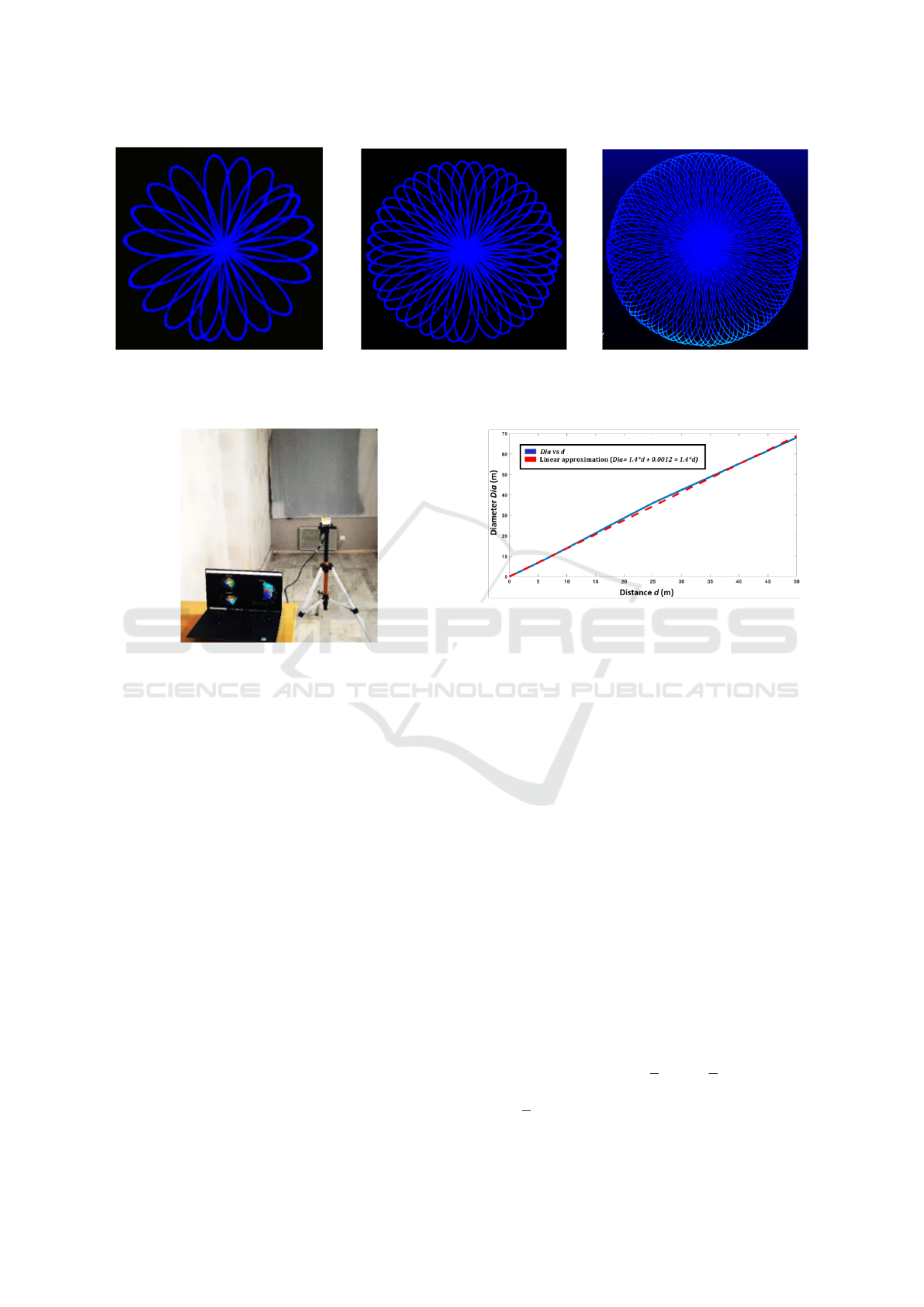
(a) 100 ms (b) 200 ms (c) 400 ms
Figure 1: Rosette – style scanning pattern of the sensor scans at different integration time.
Figure 2: Experimental setup.
In order to determine the value of k, the differ-
ent scans obtained from the sensor were analyzed (the
form and number of petals) at different integration
times, as shown in Figure 1. The number of petals
found was 200 per second. Being an even number,
this equates to a value of k = 100.
We considered the value of a as a function of scan-
ning distance. The distance of sensor was varied from
1 to 50m at regular intervals and the successive scan
patterns obtained were studied. Figure 3 presents the
size (in terms of diameter) of the rosette scan in terms
of distance.
Using a linear approximation, the value of a was
found to be:
a = 1.4 × d (4)
where d is the target distance.
4 3D SCAN REGISTRATION
The scans are registered one by one in succession.
In order to register two successive scans s
o
i
and s
o
j
,
where i and j are the number of scans, we first recon-
struct each scan (Rosette-style) at the specified target
Figure 3: The size (in terms of diameter) of the rosette scan
with respect to the target distance.
distance d applying the equations (2) and (3) using
the values of k and a determined in the previous sec-
tion. The distance d in (4) is taken as the distance of
the farthest vertical plane, perpendicular to the sensor
plane, detected in each scan.
The centres c
r
i
and c
r
j
of the successive recon-
structed Rosette-style scans s
r
i
and s
r
j
are first aligned
and then in the second step their orientations are
aligned and rotations around the three axes, i.e. θ
x
,
θ
y
and θ
z
respectively, are estimated as shown in Fig-
ure 4.
In order to align the orientation, the surface
normal vector is estimated for each of the recon-
structed scan using Principal Component Analysis
(PCA) (Klasing et al., 2009). Given a set of points in
each reconstructed scan D = x
i
np
(i=1)
, the PCA surface
normal approximation for a given data point p ∈ D is
typically computed by first determining the K-Nearest
Neighbors, x
K
∈ D, of p. Given the K neighbors, the
approximate surface normal is then the eigenvector
associated with the smallest eigenvalue of the sym-
metric positive semi-definite matrix:
V =
K
∑
k=1
(x
k
− p)
T
(x
k
− p) (5)
where p corresponds to the centers c
r
i
and c
r
j
of the
Robust 3D Point Cloud Registration Exploiting Unique LiDAR Scanning Pattern
681
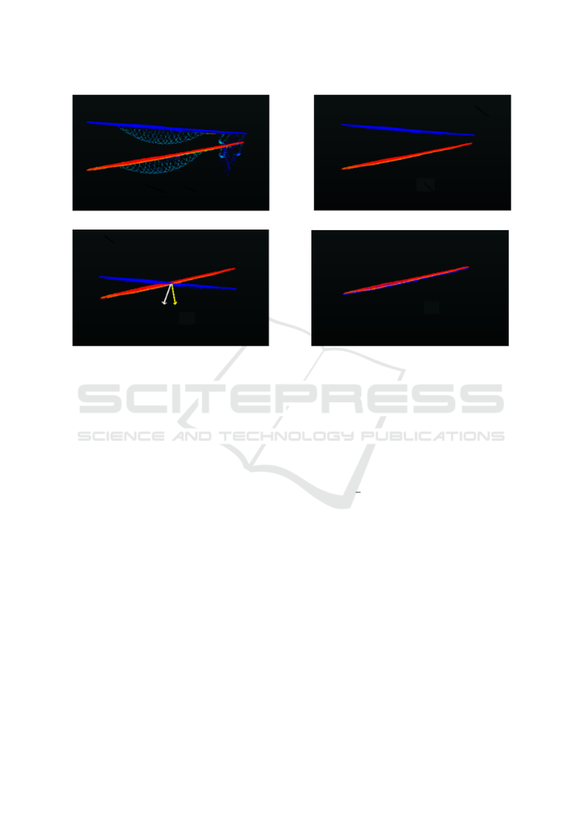
(a) (b)
(c) (d)
Figure 4: Figure (a) shows the two original successive scans with objects. Figure (b) presents the reconstructed scans cor-
responding to the two original scans without objects. In (c), the centers of the two scans are aligned, and normal vectors
estimated while in (d) the second scan is rotated to align with the first scan and the difference of normal vectors give θ
x
, θ
y
, θ
z
.
successive reconstructed Rosette-style scans s
r
i
and
s
r
j
.
The rotation around the three axis is then esti-
mated as the difference between the orientation of the
two normal vectors. As the sensor remains on the
ground, the rotation in successive scans around the
axe perpendicular to the sensor plane is considered
zero.
θ
x
= (θ
x1
− θ
x2
)
θ
y
= (θ
y1
− θ
y2
) (6)
θ
z
= (θ
z1
− θ
z2
) ≈ 0
where θ
x1
, θ
y1
, θ
z1
and θ
x2
, θ
y2
, θ
z2
are the orienta-
tions of the two vectors with respect to x, y and z axis,
respectively.
The original scans s
o
i
and s
o
j
are then matched
with the corresponding reconstructed scans s
r
i
and s
r
j
.
As the reconstructed scans are free of objects, this al-
lows the extraction of objects present in the original
scans leaving behind holes. The reconstructed scans
help complete the farthest and largest vertical plane
in the original scans occluded by objects in the scene.
All 3D points lying outside this vertical plane are then
considered as object points and are extracted out leav-
ing behind holes. The centroid P of the resulting holes
in the original scans are calculated using a bounding
box around each hole (or extracted object) with re-
spect to c
o
i
and c
o
j
as shown in Figure 5. The dis-
placement of these centroids with respect to the centre
of the scans in the successive scans provides us with
the translation, i.e. t
x,y
, between the two successive
scans:
t
x,y
=
1
n
n
∑
m=1
(P
m
j
− c
o
j
) − (P
m
i
− c
o
i
)
(7)
where n is the total number of holes (due to ex-
tracted objects) in the scans, P
m
i
and P
m
j
are the cen-
troids of the m
th
hole in the scans s
o
i
and s
o
j
, respec-
tively. The displacement along the z axis is denoted
t
z
= (d
i
− d
j
), where d
i
and d
j
are the distances of
the farthest vertical plane, perpendicular to the sensor
plane, detected in each scan, respectively.
These rotations R(θ
x
, θ
y
, θ
z
) and translations
T(t
x
, t
y
, t
z
) are then used to transform the original
scans, with the first scan taken as reference, using (8).
The transformed scan and the reference scan are then
aggregated (9) to form the new reference scan for the
next scan.
ˆs
o
j
= R.s
o
j
+ T (8)
s
o
i+1
= ˆs
o
j
+ s
o
i
(9)
The method is summarized in Algorithm 1.
ICPRAM 2024 - 13th International Conference on Pattern Recognition Applications and Methods
682
(a) (b)
(c) (d)
(e) (f)
Figure 5: Figures (a) and (b) show the two original successive scans with objects. (c) and (d) present the two scans with
holes after extraction of objects. (e) and (f) show the bounding box around the different holes in both scans, along with their
centroids and the vectors from the center of the scans and the centroids. The difference in these vectors (displacement of
objects with respect to the scan center) provides us the estimates of t
x
and t
y
.
5 EXPERIMENTS AND RESULTS
In order to evaluate the proposed method, the sen-
sor was employed in two different modes. In the first
mode, it was mounted on a tripod and moved around
different positions to completely scan an indoor room
equipped with furniture (Experiment 1) while in the
second mode, it was mounted on a small mobile
robot moving on a predefined trajectory, at a speed
of about 1 ms
−1
, scanning an enclosed hangar/parking
Robust 3D Point Cloud Registration Exploiting Unique LiDAR Scanning Pattern
683
Data: 3D scans s
o
i
and s
o
i+1
Result: s
o
i+1
= ˆs
o
i+1
+ s
o
i
for i ← 1 to total number of scans do
Reconstruct Rosette style scan s
r
i
and
s
r
i+1
at distance of farthest vertical plane
detected;
Align centers of s
r
i
and s
r
i+1
;
Estimate the surface normal vector V for
s
r
i
and s
r
i+1
;
Estimate the rotations θ
x
, θ
y
, θ
z
as
difference of orientation between the
two normal vectors;
Compare s
o
i
and s
o
i+1
with s
r
i
and s
r
i+1
,
respectively, to extract m number of
objects;
Compute bounding box around the m
holes in each scan and their centroids
P
m
i
and P
m
i+1
;
Compute vectors from centroids P
m
i
and
P
m
i+1
to the centers of s
o
i
and s
o
i+1
, i.e.
c
o
i
and c
o
i+1
, respectively;
Compare the vectors in the successive
scans to determine t
x
and t
y
;
Calculate t
z
= d
i
− d
i+1
;
Transform s
o
i+1
with respect to s
o
i
:
ˆs
o
i+1
= R.s
o
i+1
+ T;
end
Algorithm 1: 3D Scan Registration.
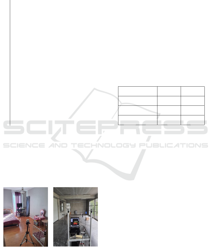
(Experiment 2), as shown in Figure 6. Scanning
was done at an integration time of 200 ms. Experi-
ment 1 contained 35 scans while Experiment 2 con-
tains 357 scans. In both cases, loop closure was
ensured to help in the evaluation process while the
ground truth was obtained via physical measurements
of the different room dimensions.
(a) (b)
Figure 6: (a) and (b) show the experimental setup for Ex-
periment 1 and Experiment 2.
Using these data, the proposed method is com-
pared with a state-of-the-art Global Iterative Closest
Point (G-ICP) (Aijazi et al., 2019) and Fast Point Fea-
ture Histograms FPFH methods (Rusu and Cousins,
2011).
5.1 Registration Accuracy
The registration results for both experiments are pre-
sented in Figure 7. A quantitative analysis is pre-
sented in Table 2 for the two experiments and com-
pared with the state-of-the-art methods. ∆E presents
the registration error calculated in terms of average
absolute difference in dimensions (width and height)
of all the walls as compared to the ground truth (sim-
ilar to Aijazi et al. (2013)).
Table 2: Registration Accuracy for Experiment 1 and Ex-
periment 2.
Experiment 1 Experiment 2
∆E (m) ∆E (m)
Proposed
method
0.018 0.043
G-ICP
Aijazi et al. (2019)
0.012 0.024
FPFH
Rusu and Cousins (2011)
0.017 0.044
The results show that the proposed method is com-
parable to the other state-of-the-art methods in terms
of accuracy. The registration accuracy of the proposed
method was better in Experiment 1 and closer to G-
ICP as the room size was small and there were less
number of scans. In case of Experiment 2, G-ICP out-
performs the other methods. This is because, in the
G-ICP algorithm, there is a bundle adjustment step at
the end to improve the overall scan registration. So
the number of scans (or size of acquisition) has less
impact on the overall results, whereas in the proposed
method, the registration error usually tends to accu-
mulate more with larger number of scans (acquisition
size) as seen in the results.
5.2 Processing Time
The proposed method along with the other state-of-
the-art methods were run on the same laptop (proces-
sor Intel Core i9-10885H, CPU @ 2.40 GHz, mem-
ory 32 GB) under Windows 10 operating system. The
results of the registration time (in seconds) are pre-
sented in Table 3.
From the results, it can be seen that there is not
a significant difference in the processing time, espe-
cially in case of Experiment 1, at this lower scan res-
olution (number of points per scan).
ICPRAM 2024 - 13th International Conference on Pattern Recognition Applications and Methods
684
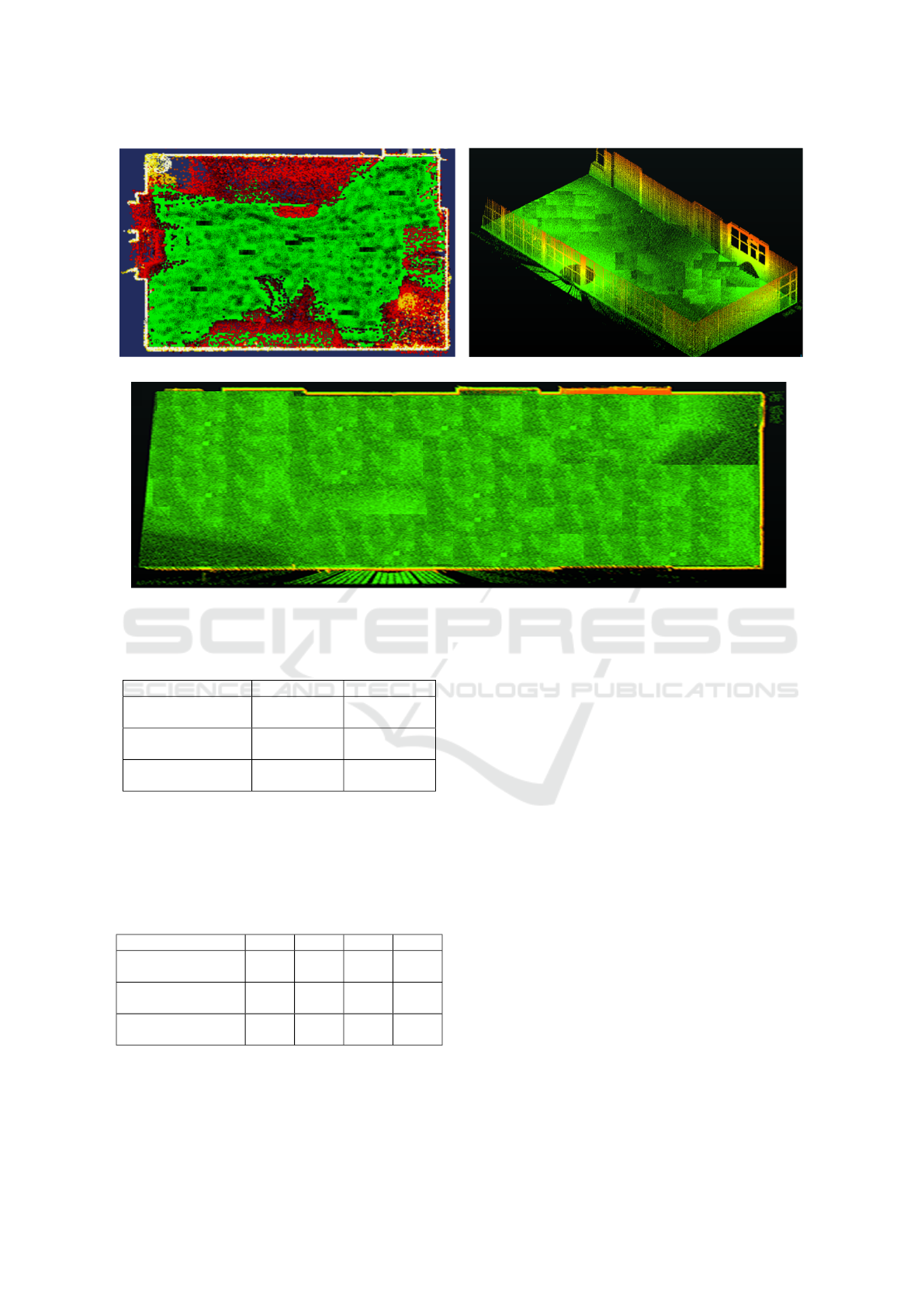
(a) (b)
(c)
Figure 7: (a), (b) and (c) show the registration results for Experiment 1 and Experiment 2 employing the proposed method.
Table 3: Processing time.
Experiment 1 (s) Experiment 2 (s)
Proposed
method
90 900
G-ICP
Aijazi et al. (2019)
100 1700
FPFH
Rusu and Cousins (2011)
95 1295
As the results presented in Table 3 were inconclu-
sive, the Experiment 1 was repeated at different scan
resolutions by varying the data integration time, i.e.
from 200ms (low resolution) to 500 ms (high resolu-
tion). The results are presented in Table 4.
Table 4: Processing time for different scan resolutions.
200ms 300ms 400ms 500ms
Proposed
method
90s 155s 205s 289s
G-ICP
Aijazi et al. (2019)
100s 250s 480s 875s
FPFH
Rusu and Cousins (2011)
95s 197s 352s 615s
The results demonstrate the strength of the pro-
posed method in terms of computational time as the
number of points per scan increases. For methods like
G-ICP, the processing time increases manifold with
the increase of number of points as the number of cor-
respondences between points increases. However, the
proposed method remains relatively unchanged. This
makes it more suitable for real time applications.
6 CONCLUSION
In this paper, a novel 3D registration method is pre-
sented that exploits the unique scanning pattern of the
sensor to register successive 3D scans. The method
was evaluated on real data and compared with other
state-of-the-art methods that show the prowess of the
proposed method. The results show that the method is
comparable with other methods in terms of accuracy
but surpasses them in performance in terms of pro-
cessing speed. In the proposed method, slight drift in
error is observed in case of larger distance and num-
ber of scans. However, in terms of processing time,
it is shown to be invariant to increase in number of
3D points per scan. For future, we would like to im-
prove the accuracy of the method by incorporating
some constraints like loop closure, whereas it would
also be considered to use an ICP method to further
improve or fine register the resulting point cloud.
Robust 3D Point Cloud Registration Exploiting Unique LiDAR Scanning Pattern
685

ACKNOWLEDGEMENTS
This work is supported by the International Research
Center “Innovation Transportation and Production
Systems” of the I-SITE CAP 20−25. Financial sup-
port was also received from the Auvergne-Rh
ˆ
one-
Alpes region through the ACCROBOT project (AC-
Costage haute pr
´
ecision ROBOTis
´
e − Chantier Tran-
sitique du laboratoire FACTOLAB) as part of the Pack
Ambition Recherche 2020.
REFERENCES
Aijazi, A. K., Checchin, P., and Trassoudaine, L. (2013).
Automatic removal of imperfections and change de-
tection for accurate 3d urban cartography by classi-
fication and incremental updating. Remote Sensing,
5(8):3701–3728.
Aijazi, A. K., Malaterre, L., Trassoudaine, L., Chateau, T.,
and Checchin, P. (2019). Automatic Detection and
Modeling of Underground Pipes Using a Portable 3D
LiDAR System. Sensors, 19(24).
Besl, P. and McKay, N. (1992). A Method for Registration
of 3-D Shapes. IEEE Trans. on PAMI, 14(2):239–256.
Brazeal, R. G., Wilkinson, B. E., and Hochmair, H. H.
(2021). A Rigorous Observation Model for the Ris-
ley Prism-Based Livox Mid-40 Lidar Sensor. Sensors,
21(14).
Choy, C., Dong, W., and Koltun, V. (2020). Deep Global
Registration. In Proceedings of the IEEE Computer
Society Conference on Computer Vision and Pattern
Recognition, pages 2511–2520.
He, Y., Ma, L., Jiang, Z., Tang, Y., and Xing, G. (2021).
VI-Eye: Semantic-Based 3D Point Cloud Registra-
tion for Infrastructure-Assisted Autonomous Driving.
In Proceedings of the 27th Annual International Con-
ference on Mobile Computing and Networking, Mobi-
Com ’21, page 573–586, New York, NY, USA.
Klasing, K., Althoff, D., Wollherr, D., and Buss, M. (2009).
Comparison of surface normal estimation methods for
range sensing applications. In 2009 IEEE Interna-
tional Conference on Robotics and Automation, pages
3206–3211.
Li, H., Zhao, H., Ye, B., and Zhang, Y. (2023). 3D semantic
map construction based on point cloud and image fu-
sion. IET Cyber-Systems and Robotics, 5(1):e12078.
Pais, G. D., Ramalingam, S., Govindu, V. M., Nascimento,
J. C., Chellappa, R., and Miraldo, P. (2019). 3DReg-
Net: A Deep Neural Network for 3D Point Registra-
tion. In Proceedings of the IEEE Computer Society
Conference on Computer Vision and Pattern Recogni-
tion, pages 7191–7201.
Rusu, R. B., Blodow, N., and Beetz, M. (2009). Fast Point
Feature Histograms (FPFH) for 3D registration. In
IEEE International Conference on Robotics and Au-
tomation, pages 3212–3217.
Rusu, R. B. and Cousins, S. (2011). 3D is here: Point Cloud
Library (PCL). In IEEE International Conference on
Robotics and Automation (ICRA), pages 1 – 4.
Segal, A., Haehnel, D., and Thrun, S. (2009). Generalized-
ICP. In Robotics: Science and Systems, volume 5,
pages 168–176.
Serafin, J. and Grisetti, G. (2015). NICP: Dense normal
based point cloud registration. In IEEE International
Conference on Intelligent Robots and Systems, vol-
ume 2015-Decem, pages 742–749.
Tazir, M. L., Gokhool, T., Checchin, P., Malaterre, L., and
Trassoudaine, L. (2018). CICP: Cluster Iterative Clos-
est Point for sparse-dense point cloud registration.
Robotics Auton. Syst., 108:66–86.
Wang, Y., Bu, S., Chen, L., Dong, Y., Li, K., Cao, X.,
and Li, K. (2023). HybridFusion: LiDAR and Vision
Cross-Source Point Cloud Fusion.
Wang, Z., Wang, X., Fang, B., Yu, K., and Ma, J. (2021).
Vehicle detection based on point cloud intensity and
distance clustering. Journal of Physics: Conference
Series, 1748(4):042053.
Xie, Z., Liang, P., Tao, J., Zeng, L., Zhao, Z., Cheng, X.,
Zhang, J., and Zhang, C. (2022). An Improved Super-
voxel Clustering Algorithm of 3D Point Clouds for the
Localization of Industrial Robots. Electronics, 11(10).
Xue, G., Wei, J., Li, R., and Cheng, J. (2022). LeGO-
LOAM-SC: An Improved Simultaneous Localization
and Mapping Method Fusing LeGO-LOAM and Scan
Context for Underground Coalmine. Sensors, 22(2).
Zou, Z., Lang, H., Lou, Y., and Lu, J. (2023). Plane-based
global registration for pavement 3D reconstruction us-
ing hybrid solid-state LiDAR point cloud. Automation
in Construction, 152:104907.
ICPRAM 2024 - 13th International Conference on Pattern Recognition Applications and Methods
686
