
PanoTherm: Panoramic Thermal Imaging for Object Detection and
Tracking
Thomas Kernbauer
a
, Philipp Fleck
b
and Clemens Arth
c
ICG, Graz University of Technology, Inffeldgasse 16/2, 8010 Graz, Austria
{thomas.kernbauer, philipp.fleck, arth}@icg.tugraz.at
Keywords:
Thermal Imaging, Camera Calibration, Object Detection.
Abstract:
Visible-light cameras are used traditionally in object detection and tracking. Thermal imaging can equally be
used for this purpose, however at the cost of additional calibration efforts, expenses, and limitations concerning
the field of view. Still, thermal imaging is advantageous in various scenarios and basically the only plausible
technology to apply in harsh outdoor environments, in which the use of standard RGB cameras is prohibitive
due to low-light conditions or in complete darkness. While panoramic imaging using visible light cameras
is becoming more popular for advanced photography or action recording, limited work has been done on
developing panoramic thermal cameras. In this work, we present the first panoramic thermal camera targeting
the constant 360
◦
monitoring of the environment. We describe the calibration and stitching process in detail
and demonstrate how to use the camera in a vehicular scenario. Finally, we give an example of the detection
and tracking of objects and discuss the advantages and disadvantages of thermal imaging for this purpose.
1 INTRODUCTION
In recent years visible-light cameras have become the
state-of-the-art in detecting and tracking humans and
objects. Following a vast amount of development in
the area of Computer Vision and through the hype
around autonomous driving, visible-light cameras are
nowadays the standard to apply in vehicles to increase
safety in road traffic. However, digital aids still lack
reliability, particularly under adverse environmental
conditions, leading to thousands of, partially fatal, ac-
cidents per year.
Additional mirrors on trucks or other heavy ma-
chinery, blind spot notifiers on side mirrors, and spec-
ified driver training have not led to the hoped decrease
in accidents. Studies reveal alarming numbers for,
e.g., Germany (Luis Technology, 2023), while more
recent numbers for Austria indicate no significant im-
provements concerning blind spot accidents in recent
years (Spitzer, 2023):
• 37 thousand accidents a year with 47 thousand
people involved,
• on average one hundred accidents a day, involving
128 people on average.
a
https://orcid.org/0009-0000-7539-644X
b
https://orcid.org/0000-0002-9827-2594
c
https://orcid.org/0000-0001-6949-4713
While these numbers are arguably high, they only
concern regular traffic accidents and exclude other
similar accidents with heavy machinery like, reach
stackers, snow groomers, equipment on construction
sites, and others.
More visibility, like bright colors (i.e., a warning
vest), mirrors, or visible-light cameras seem to im-
prove this situation, but their usefulness is strongly re-
lated to the environmental conditions. Fog, rain, dark-
ness, snow, dust, and sand will drastically reduce the
ability to quickly identify human beings in or close to
a blind spot.
In this work, we present a novel take on this cat-
egory of problems using a low-cost panoramic ther-
mal camera, PanoTherm, to remove blind spots to
the greatest extent possible. Using a uniform and cal-
ibrated view, we can easily detect and track objects
with certain heat signatures, especially humans. The
application of our proposed development ranges from
disaster scenarios, e.g., identifying fire hazards and
finding humans (conscious and unconscious), to the
application in areas with bad visibility, e.g., smoky
buildings or off-road, low-light navigation. Mounted
on the roof of a vehicle, persons in typical blind spot
areas are immediately recognized. Furthermore, it is
equally suited for surveillance situations like trespass-
ing or maintenance tasks like pipe inspection. In a
more futuristic use case, our panoramic thermal im-
98
Kernbauer, T., Fleck, P. and Arth, C.
PanoTherm: Panoramic Thermal Imaging for Object Detection and Tracking.
DOI: 10.5220/0012330400003660
Paper published under CC license (CC BY-NC-ND 4.0)
In Proceedings of the 19th International Joint Conference on Computer Vision, Imaging and Computer Graphics Theory and Applications (VISIGRAPP 2024) - Volume 4: VISAPP, pages
98-109
ISBN: 978-989-758-679-8; ISSN: 2184-4321
Proceedings Copyright © 2024 by SCITEPRESS – Science and Technology Publications, Lda.
age can also be used within virtual reality (VR) appli-
cations, e.g., being overlaid with a color image of a
traditional panoramic camera.
Thermal and panoramic imaging have been exten-
sively, yet separately studied. With PanoTherm, we
close the gap between these fields and introduce a
panoramic thermal camera, assembled with low-cost
longwave infrared thermal sensors. Compared to ex-
isting, very expensive panoramic thermal hardware
with a rotating sensor, the major advantage of Pano-
Therm is the uninterrupted omnidirectional view at
comparably high frame rates, coming at a price tag in
the low 5-digit USD area. The proposed algorithms
are largely independent of the underlying hardware
and can therefore be seamlessly applied to a wide
range of devices. Our main contributions are:
• a thermal image calibration workflow that allows
the calibration of multiple rigidly assembled ther-
mal sensors with very little preparation;
• a working prototype for an omnidirectional thermal
camera. This includes the 3D printed and assem-
bled camera case as well as the software framework
for stitching the thermal images in real-time with-
out the need for re-calibration;
• a methodology to register the panoramic thermal
camera rig with respect to its environment, giving
measurements a context in the 3D world; and
• an example of object detection and tracking in the
360
◦
thermal domain in a vehicular setup.
Finally, we demonstrate our contributions in the
field and track targets not only across the individual
camera views but also estimate the real-world posi-
tion, visualize it in a radar-like manner, and discuss
our findings in the latter of this work.
2 RELATED WORK
In the following, we quickly review the areas of cam-
era calibration, panoramic imaging, and thermal ob-
ject detection and tracking.
2.1 Camera Calibration
Intrinsically and extrinsically calibrated cameras are
the foundation of any image-based real-world related
measurements. Being a well-studied field, almost
every camera model features its own methodology.
Modern takes on single and multi-camera array cal-
ibration were presented by Zhang et al., (Zhang,
2000). The foundation of all algorithms is to es-
tablish correspondences between real-world patterns
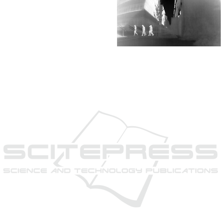
Figure 1: Exemplary thermal imagery taken with one of
PanoTherm off-the-shelf thermal seek cameras.
(e.g., checkerboard) and their imagery. By reducing
the measured error, the camera parameters can be es-
timated. In the thermal domain, geometric features
blocking infrared (IR) light have to be exploited to
derive such correspondences (Lag
¨
uela et al., 2011;
Yang et al., 2011; Ellmauthaler et al., 2013). Wired
metal structures in combination with resistors (Ng and
Du, 2005), patterns printed from aluminum (Usamen-
tiaga et al., 2017), heated (Saponaro et al., 2015), or
cooled (Herrmann et al., 2019) structures, lead to ac-
ceptable results for thermal cameras. However, with
PanoTherm we implement a circular cutout board
for the calibration of all cameras, described in Sec-
tion 3.1.
2.2 Thermal Imagery Applications
Thermal cameras are a commonly used alternative
to visible-light cameras due to their independence
from visible light sources and their capacity to sense
through obstructions such as fog or smoke. Gade
and Moeslund (Gade and Moeslund, 2014) demon-
strate advantages in complex environmental scenar-
ios. Furthermore, thermal imaging technology has
led to the development of smaller and more affordable
thermal cameras (Systems, 2011), expanding their us-
ability and impact across different sectors such as in-
dustry, medical, or home automation. Such devices
utilize uncooled microbolometer sensors to capture
long-wave infrared (LWIR) emissions.
Microbolometers contain vanadium oxide or
amorphous silicon resistors, which change their elec-
trical resistance depending on the impact of the elec-
tromagnetic radiance of certain wavelengths.
More specifically, LWIR sensors can capture in-
frared radiations with wavelengths between 8 − 14
µm. Jewett and Serway (Jewett and Serway, 2008)
mention that, according to Wiens law, the emit-
ted electromagnetic radiance of room temperature
(20
◦
) objects peaks at roughly 9 µm. Applications
reach from agronomy (Yanmaz et al., 2007; Ha-
lachmi et al., 2019), agriculture (Vadivambal and
Jayas, 2011; Messina and Modica, 2020), mainte-
PanoTherm: Panoramic Thermal Imaging for Object Detection and Tracking
99

Figure 2: Assembly of the panoramic thermal camera in a rectangular shape. Each camera has about 105
◦
horizontal FOV,
leaving an overlapping area between the individual cameras of approximately 15
◦
.
nance (Hoegner and Stilla, 2009; Venegas et al.,
2022), medical diagnostics (Ring and Ammer, 2012;
Sousa et al., 2017), robotics (Fehlman and Hin-
ders, 2009), surveillance (Kri
ˇ
sto et al., 2020), to au-
tonomous driving (Rosique et al., 2019).
2.3 Panoramic Imaging
The process of combining images into mosaics is a
long-standing computer vision problem, elaborated
by Milgram (Milgram, 1975) and others. Due to the
advantages of panoramic images, i.e., the increased
field-of-view (FOV) and higher resolutions, or the
same frame of reference – the applications are mani-
fold. These include the creation of panoramic scenes
for augmented reality (AR) (Wagner et al., 2010),
scene understanding in the autonomous driving do-
main (Zhang et al., 2021), depth estimation (Zioulis
et al., 2018), visual odometry (Zhang et al., 2016),
or other robotics applications (Cheng et al., 2019).
This versatility is also reflected in underlying cam-
era systems. Besides the utilization of smartphones
to take scenic photos, panoramic or 360
◦
images
can be captured by vastly different sensors setups,
e.g., rigid multi-camera arrays (Lin et al., 2018), fast
rotating single cameras (Thomas et al., 2019), fish-
eye lenses (Ho and Budagavi, 2017), or the usage of
panoramic annular lenses (Powell, 1994).
In the context of thermal imaging, sensor se-
tups resort to rotating single cameras (Thomas et al.,
2019), the application of a catadioptric mirror (Zeng
et al., 2020), or, similar to our approach, a multi-
camera setup (Cowan et al., 2019).
However, all approaches rely on either knowing
rigid transformations between individual cameras or
the pan-tilt-yaw state of acquired images. Such infor-
mation is leveraged to obtain a single panorama.
2.4 Thermal Object Detection
Numerous (semi-) autonomous applications like col-
lision avoidance, obstacle detection, pedestrian detec-
tion, and more, benefit from object detection and ob-
ject tracking. Since this is a well-researched area, we
will only highlight a view of relevant works within the
thermal domain. With the success of deep learning-
based object detection, single-stage object detection
methods such as you only look once (YOLO) (Red-
mon et al., 2016) or single shot detector (SSD) (Liu
et al., 2016) were applied in the thermal domain.
Namely, Krivsto et al., (Kri
ˇ
sto et al., 2020) employ
YOLO-based methods, and Dai et al., (Dai et al.,
2021) implement a method based on the SSD archi-
tecture. This method called TIRNet, modifies the
original SSD model architecture by extending it with
residual branches, to extract features from the low-
resolution IR images.
The tracking-by-detection (TBD) paradigm suc-
cessfully dominates various multi-object tracking
benchmarks, such as MOT17 (Milan et al., 2016)
or MOT20 (Dendorfer et al., 2020). TBD meth-
ods, e.g., simple online and realtime (SORT) (Bew-
ley et al., 2016)-based trackers or ByteTrack (Zhang
et al., 2022) associate bounding boxes resulting from
the object detection method to create tracks. In Sec-
tion 6, we demonstrate the use of YOLO and Byte-
Track with PanoTherm to precisely detect, track, and
localize humans for accident avoidance.
3 MULTI CAMERA ARRAY
Traditional thermal cameras for small-scale monitor-
ing feature a very limited horizontal field-of-view
(FOV) of 15
◦
to 60
◦
. The PanoTherm assembly re-
quires FOVs of at least 105
◦
with four cameras. One
capable and cost-efficient candidate is the Thermal
Seek Mosaic Cores C312NPX
1
featuring a 2.2mm
lens and 320 × 240 pixels at a frame rate of about
27Hz. The horizontal FOVs measure 105
◦
, yielding a
15
◦
degree overlap between the views. In Figure 1 we
showcase an exemplary image taken with one of the
1
Mosaic Core: https://www.thermal.com/mosaic-core-320x240-2mm.html
VISAPP 2024 - 19th International Conference on Computer Vision Theory and Applications
100
utilized thermal cameras. Figure 2 depicts the custom
3D printed enclosure, the rectangular arrangement of
the cameras, and their approximate FOV projections.
Each camera is connected to a USB3-Hub based
on the assembly, such that only a single power and
a single data cable connect the device to a comput-
ing platform (e.g., laptop computer, single board com-
puter). Figure 4 depicts a panoramic image cap-
tured with PanoTherm consisting of the four individ-
ual cameras. Due to the comparably low amount of
data (i.e., only a fraction of modern color images) a
serial USB connection is more than sufficient to cap-
ture images simultaneously.
3.1 Camera Calibration
Because of their shared characteristics and compara-
ble lens geometry, the pinhole camera model (Hartley
and Zisserman, 2003) can be applied to commonly
used thermal cameras. Thus, allowing us to apply the
same geometric and mathematical properties to com-
pute intrinsic properties. Points in images x
I
∈ R
3
and the 3D points in the world x
W
∈ R
4
are expressed
as homogeneous coordinates, i.e., x
I
= (x
i
,y
i
,1)
⊤
and
x
W
= (x
w
,y
w
,z
w
,1)
⊤
. Following the pinhole camera
model, the relation between image and world points is
formalized by the camera projection matrix P ∈ R
3×4
as follows
µ x
I
= P x
W
with P = K [R | t]. (1)
Here, µ corresponds to an arbitrary scale factor. The
projection matrix P is composed of the extrinsic pa-
rameters rotation R ∈ R
3×3
and translation vector
t ∈ R
3
as well as the intrinsic parameters, i.e., the
camera matrix K ∈ R
3×3
. Camera calibration with
a planar calibration pattern uses this relation, by as-
suming the z coordinate of 3D world points to be 0.
Expressing this assumption with Equation (1) yields
µ x
I
= K
r
00
r
01
r
02
t
0
r
10
r
11
r
12
t
1
r
20
r
21
r
22
t
2
x
w
y
w
0
1
= H
x
w
y
w
1
(2)
Here, H ∈ R
3
corresponds to the homography, which
relates the real-world calibration points with the de-
tected positions in pixel space. Since H is defined up
to a scale factor, at least 4 point-to-point correspon-
dences are necessary to obtain a solution.
Real cameras deviate from the optimal pinhole
camera model due to imperfections introduced by
their lenses, i.e., the pinhole aperture, as well as x
W
and x
I
, being not co-linear. Hence, the mathemat-
ical model has to account for lens distortion. Fol-
lowing (Hartley and Zisserman, 2003; Heikkila and
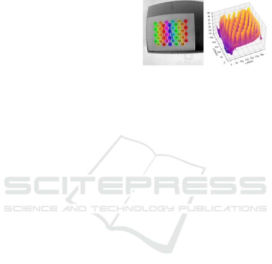
Figure 3: (Left) The common image calibration approach
utilizing an asymmetric grid in front of an LCD screen.
(Right) Thermal profile of the asymmetric circular calibra-
tion pattern in front of an LCD.
Silv
´
en, 1997), radial and tangential distortion can be
approximately corrected by
x
c
= x
d
+ F
D
(x
d
,δ), (3)
with x
d
∈ R
2
being the distorted image pixel, x
c
∈ R
2
being the corrected image pixel and F
D
being a higher
order polynomial with coefficients
δ = (k
1
,k
2
,..., p
1
, p
2
,. ..)
⊤
. (4)
Given n images with m calibration points each,
Zhang (Zhang, 2000) proposed to apply the
Levenberg-Marquardt algorithm (Mor
´
e, 1977) for the
maximum-likelihood estimation (MLE), i.e.,
n
∑
i
m
∑
j
∥x
i j
−
ˆ
x(K,δ,R
i
,t
i
,x
W, j
∥
2
. (5)
3.2 Pattern Calibration
Pattern-based calibration approaches have success-
fully been shown by Vidas et al., (Vidas et al., 2012),
being a direct inspiration to our approach. We uti-
lize an asymmetric circular calibration pattern. To
detect the pattern in the thermal image, the IR light
is blocked by simple irregular circular cut-outs. The
resulting plate is placed in front of the liquid-crystal
display (LCD) to block off light around the irregular
circles. Figure 3 (left) shows the detected pattern and
Figure 3 (right) the thermal response, where the peaks
are the passed-through IR radiation of the monitor.
Backlights used in modern computer screens are
significantly warmer than the ambient room tempera-
ture. Hence, the temperature difference between the
calibration board in front and the screen itself is vis-
ible in the thermal image, consequently allowing us
to apply traditional calibration methods. Commonly
used tools like the OpenCV (Bradski, 2000) can be
directly applied to the calibration process.
PanoTherm: Panoramic Thermal Imaging for Object Detection and Tracking
101

Implementation Details. The pattern is detected
using OpenCV’s findCirclesGrid function. How-
ever, if the blob detection algorithm is not successful,
we simply apply the adaptiveThreshold function.
Passing the resulting image to findCirclesGrid
usually succeeds in extracting the calibration pattern
from the thermal image. Hence, we can make use of
the calibrateCamera function to retrieve a calibra-
tion.
3.3 Image Acquisition
Acquiring images in a fixed multi-camera arrange-
ment poses specific challenges that do not require ad-
dressing within a single-camera panoramic pipeline,
e.g., synchronization of the utilized camera heads or
bandwidth considerations. Especially in the context
of panoramic images that capture moving objects,
synchronization is highly important to avoid ghosting
and other artifacts.
PanoTherm relies on event-driven camera call-
backs and polling to achieve synchronization. Since
each camera supports frame rates of up to 27 Hz, a
registered call-back function for each camera head
updates the separate data structures once a frame
is ready in an asynchronous manner. To create a
panorama, the data structures are naively polled and
processed as depicted in Figure 6. On modern com-
puter hardware, the cost of storage and processing of
a panorama sequence is negligible. Hence, in our ex-
periments, the synchronicity of the acquired frames
proved to be sufficient as we did not witness artifacts
between frames for moving objects.
4 IMAGE STITCHING
Image stitching is a fundamental computer vision task
that involves combining multiple overlapping images
to create a panoramic scene. The number of differ-
ent algorithms and approaches showcase the long-
standing research interest in this problem (Szeliski
et al., 2007).
In many image stitching workflows, e.g., the case
of panoramic imaging from a single camera (Wag-
ner et al., 2010), the camera positions are unknown
and therefore feature tracking and matching, as well
as global image alignment, is necessary to produce a
panoramic image. This is different in a rigid camera
setup. Once calibrated, the panoramic image can be
composed by simply utilizing the previously derived
camera matrices.
4.1 Stereo Calibration
To find the extrinsic parameters between cameras,
feature matching is usually employed (Hartley and
Zisserman, 2003). However, in cases with nar-
row, distorted, or low-resolution overlapping regions,
feature-extraction methods such as SIFT (Lowe,
1999) and ORB (Rublee et al., 2011), are not insuf-
ficient to extract congruent features. Therefore, we
utilize easily detectable patterns, i.e., the calibration
pattern depicted in Figure 3, and place them in the
overlapping FOV of adjacent cameras to find corre-
spondences. With this, standard stereo calibration can
be applied to estimate the rotation and translation be-
tween the cameras.
Given a point in image i x
i
= (x
i
,y
i
,1)
⊤
and in the
same pixel coordinates which correspond to the point
x
i
in image j x
j
= (x
j
,y
j
,1)
⊤
, the relation
x
i
Fx
j
= 0 (6)
is leveraged to calculate the extrinsic parameters.
F ∈ R
3×3
corresponds to the fundamental matrix
which encapsulates the algebraic representation of the
epipolar geometry of the scene. We refer the reader to
Hartley and Zisserman (Hartley and Zisserman, 2003)
for more details.
4.2 Cylindrical Warping
The obtained extrinsics are utilized in cylindrical im-
age warping. We chose to warp and blend our ob-
tained scenes, due to its advantages for visualization
and registration. This includes the possibility to eas-
ily unwrap the map on a planar surface and utilize the
geometric properties for our registration purposes.
To warp the images on the cylindrical canvas, we ap-
ply backward mapping. Following (Wagner et al.,
2010), we apply
R = O · µ(x
cyl
) (7)
x
camera
= K · δ (π(R)) (8)
x
pixel
= interpolate (x
camera
)) (9)
to project points on the cylinder x
cyl
into the pixel
coordinates x
pixel
. First, we apply the function µ to
project the point on the cylinder to a ray. This ray is
then rotated according to an orientation O. With the
function π, we convert R into the image plane. After
applying radial distortion with δ, we can project the
point into the camera frame by multiplying it with the
intrinsic matrix K. Finally, the pixel value is chosen
by interpolation. This yields x
pixel
, the color value for
the panoramic coordinate x
cyl
.
VISAPP 2024 - 19th International Conference on Computer Vision Theory and Applications
102
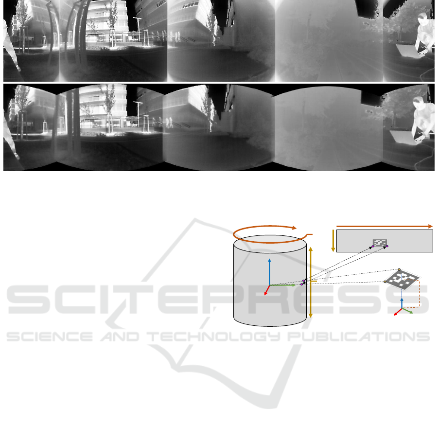
Figure 4: A naively stitched panorama (top) in comparison with a calibrated stitched panorama (bottom) of the same scene.
The improvements are visible in the overlapping regions, e.g., there are no duplicate persons in the center of the panorama or
the structure of objects is consistent across cameras.
4.3 Limitations
The number of cameras we employ is minimal con-
cerning our goal to capture a full 360
◦
panorama.
While Figure 4 shows good geometric accuracy,
seams in the overlap areas are visible. Our use case
targets the detection of thermal signatures, which
means that the real temperature values, respectively
the visual appeal of the panorama, are less impor-
tant. Each camera is automatically adapting to spread
the available value range, i.e., [0, 255], to maximize
the preserved information content. This implies that
the individual ranges correspond to different abso-
lute temperature ranges, resulting in a panoramic view
similar to one created from multiple RGB cameras
missing brightness and contrast adaption.
As PanoTherm is constructed out of separate cam-
eras, the parallax between frames is apparent. These
limitations could be addressed with geometrical algo-
rithms, e.g., multi-perspective plane sweep (MPPS)
algorithm (Kang et al., 2004; Uyttendaele et al.,
2004) or image based solutions, e.g., Stretching
Stereo (Kang et al., 2004).
5 CAMERA-TO-WORLD
REGISTRATION
In order to give measurements in the panoramic view
meaning in terms of direction and distance with re-
gards to the given environment, the camera rig has
to be registered in a coordinate system. We em-
ploy a modified version of the known Perspective-
3-Point (P3P) algorithm (Fischler and Bolles, 1981)
Yc
Z
c
X
c
a
b
0
0
Image Coordinate System
Y
I
X
I
Cylindrical Coordinate
System
3D World Coordinate
System
Y
W
Z
W
X
W
C
W
C
C
h
artk
Figure 5: Illustration of the image to 3D world point map-
ping through the cylindrical coordinate system. Image
coordinates x
i
,y
i
are mapped into cylindrical coordinates
α
i
,β
i
. Knowing the 3D positions of the marker corners,
i.e., x
w
,y
w
,z
w
, we can solve the PnP problem and resolve
the transformation between C
c
and C
w
.
used for panorama localization in Arth et al., (Arth
et al., 2011).
PanoTherm is placed in a given environment with
one of the cameras facing to the front to reduce the
impact of image distortion. In the field of view of
this camera, a flat AR toolkit (ARTK+) marker (Wag-
ner and Schmalstieg, 2007) is placed to form the
world coordinate center C
w
. As our panoramic im-
age is a mapping onto a cylindrical surface each pixel
in the panorama can be represented as a ray ema-
nating from the center of the cylinder through the
cylindrical surface with two angles, α and β. More
specifically, a point in the panoramic image domain
x
pano
= (x
pano
,y
pano
) is converted into cylindrical co-
PanoTherm: Panoramic Thermal Imaging for Object Detection and Tracking
103
ImageAcquisition
Pa noramicStitching
Detection
RealWorld
Positi on
Estimator
and
Mapper
Localizedresultswithi nthepanoramicview,in3Dandrelativetotheregisteredvehicle
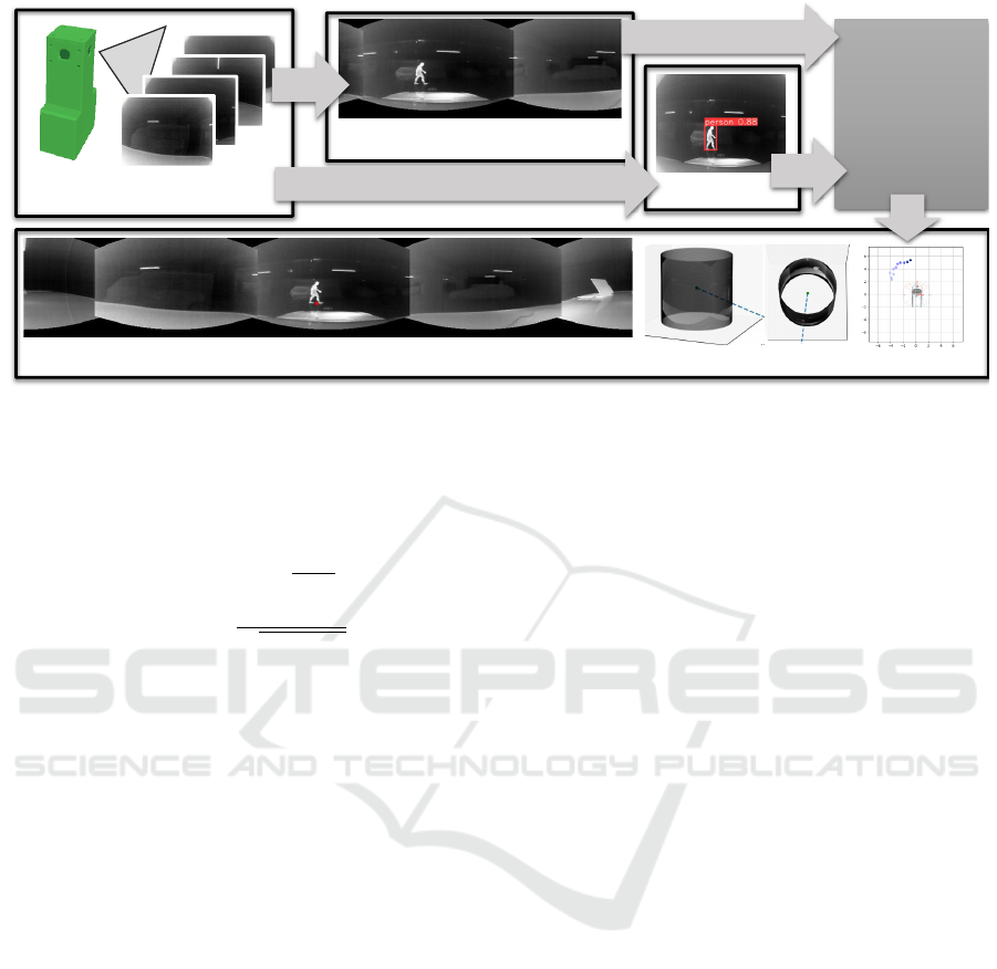
Figure 6: Block diagram representation of the proposed concept around PanoTherm. The images acquired by individual
sensors (top left) are registered and stitched into a panoramic view (top middle). Similarly, MOT is used to detect humans in
the actual imagery (top right). Using the detection results, the registration, and the cylindrical representation, we can represent
the position and motion of detected objects with respect to the vehicle registered (bottom).
ordinates x
cyl
= (x
cyl
,y
cyl
) as follows
x
cyl
= sα = stan
−1
x
pano
f
, (10)
y
cyl
= sβ = s
y
pano
q
x
2
pano
+ f
2
. (11)
Here, s is a scaling factor and f corresponds to the
focal length (Szeliski et al., 2007).
We can thereby convert image measurements
to rays emanating from the center of C
c
and
going through individual points x
cyl
, and mea-
sure their pairwise angle. The corresponding 3D
points of the marker corners all have coordinates
(±l
artk
/2,±l
artk
/2,h
artk
). In a general setup, we as-
sume h
artk
= 0 which results in the marker center be-
ing the center of the world coordinate system C
w
.
Figure 5 depicts an illustration of these relation-
ships. Reformulating the P3P problem we solve the
polynomial equation system similar to the one solved
in the pinhole case, giving us the transformation be-
tween the coordinate systems C
c
and C
w
in the form
of [R
pt
|t
pt
].
5.1 Real World Position Estimator
For the composition of the panoramic image, we uti-
lize backward warping (see Section 4.2). To project
a point from the panoramic image into the real world,
we apply forward warping.
In a practical scenario, we can assume that the ob-
served environment is mostly flat and can be approxi-
mated through a ground plane P. Putting the ARTK+
marker upright on the ground during registration, P is
trivially given as z = 0. First, we can convert x
cyl
fol-
lowing Equations (10) and (11). Then, we convert it
into a ray emanating the coordinate center C
c
and go-
ing through x
cyl
. Note that the 3D world coordinates
of the center of C
c
are given by
c
c
= −R
pt
T
t
pt
. (12)
Lastly, we intersect this ray with the plane P to deter-
mine the approximate 3D position, i.e., the distance
and heading, relative to the world coordinate system
C
w
.
An illustration of this concept is later shown in our
experimental setup in Figure 10. The relative heading
α
′
determines the relative orientation of an object to
C
w
, respectively the distance d can be calculated from
β
′
1
. From the assumption that the object in question
is oriented upwards, we can additionally use β
′
2
to de-
termine the approximate object height.
6 EXPERIMENTS
To evaluate PanoTherm, we employ the sensor sys-
tem on a real car. This includes the registration of our
system with respect to the car itself, the detection and
tracking of pedestrians in proximity to the car in the
panoramic image, and the utilization of the cylindri-
cal geometry to re-project the detected objects con-
cerning the car into real-world coordinates. Figure 6
displays the workflow of our use case.
VISAPP 2024 - 19th International Conference on Computer Vision Theory and Applications
104
X
C
Y
C
Z
C
CAM1
CAM2
CAM3
CAM4
w
/2
v
artk
C
C
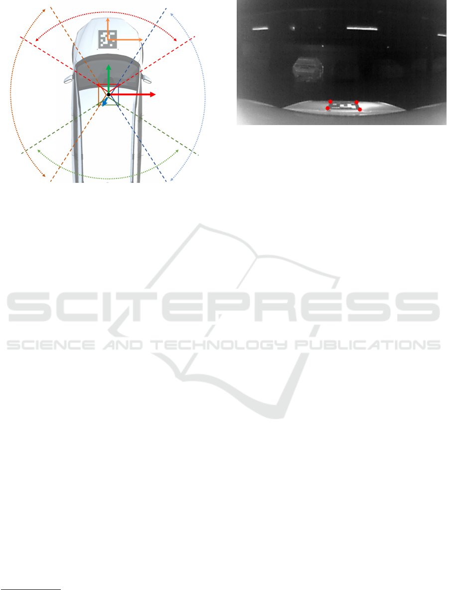
Figure 7: Registration with respect to a given environment.
As the camera rig is internally calibrated and represents
the coordinate center C
c
, it is sufficient to use a standard
ARTK+ marker with a known size on the engine hood with
a known approximate height above ground.
6.1 Registration
As we are mainly interested in blind-spot avoidance
on a vehicle, we perform an illustrative setup as
shown in Figure 7 and leave out exact measurements
for now. PanoTherm is mounted on the roof of a ve-
hicle with one of the cameras facing to the front. A
flat ARTK+ marker (Wagner and Schmalstieg, 2007)
made from steel with a known edge length l
artk
is
mounted on the engine hood pointing upwards. For
simplicity, we measure the approximate height above
ground h
artk
. Similarly, we measure the approximate
distance of the marker from the front end of the car,
v
artk
, with a standard meter. Mounting the marker in
the middle of the hood, we can further infer the dis-
tance of the marker center to w/2 with w denoting the
known width of the car.
Once the engine of the car warms up, the marker
becomes visible in the image of the front-facing cam-
era, allowing us to detect it in the thermal image
2
. An
example image is shown in Figure 8. By using h
artk
for the z-coordinate of the marker corners in the reg-
istration step described in Section 5, we can place the
world coordinate center C
w
perpendicularly below the
marker center on the ground plane P, such that our as-
sumption of P given by z = 0 holds. We finally arrive
at a registration of PanoTherm with respect to C
w
, be-
ing a coordinate system anchored to the vehicle.
2
Note that we used manual thresholding for simplicity,
however, a targeted implementation of ARTK+ could detect
the marker automatically as well.
Figure 8: Thermal signature of the marker as seen from the
front-facing camera.
6.2 Object Detection and Tracking
We utilize a YOLOv8 model and train it on the
KAIST (Hwang et al., 2015) dataset before applying
fine-tuning on a small custom dataset. As described
previously, the thermal range between single cameras
is not equalized over the whole panorama to improve
the visible range of each image. Therefore, we abstain
from using image-based re-identification models and
leverage motion-based predictions in the multi-object
tracking (MOT) module. Note that our main goal is to
prove the proposed concept and not the evaluation of
different detection and tracking methods in terms of
performance in the thermal domain. An example of
human detection using this setup is shown in the red
frame in Figure 9.
6.3 Reprojection and Height Estimation
The MOT framework leaves us with bounding boxes
B ∈ R
6
, each defined by identifier, class, height,
width, and location in the image domain. To project
the lower edge of the bounding box into real-world 3D
coordinates, we utilize the geometrical properties of
the cylindrical projection (see Section 5.1). The posi-
tion of the bounding box in 3D is further processed to
obtain the height of the detected object. For this, we
again intersect the vertical plane of the detection with
the ray resulting from the upper edge of the bounding
box. Since PanoTherm is fully registered, the con-
version between 3D world coordinate system C
w
and
cylindrical coordinate system C
c
is solved. Hence, we
can simply apply [R
pt
|t
pt
] to convert the coordinates
from one frame into another.
Figure 10 showcases the geometrical relation of
these two coordinate frames in our use case. This
leaves us not only with the 3D position in world coor-
dinates but also with the height of the object.
Since the viewing angle is obstructed by the car
roof, we apply a manually picked threshold to the
PanoTherm: Panoramic Thermal Imaging for Object Detection and Tracking
105
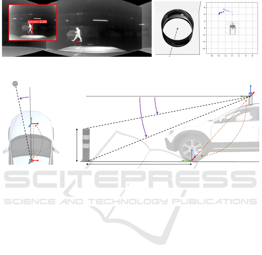
Figure 9: Tracking a human across several frames in the panoramic space. Left, the panorama, the center bottom point, and the
raw output of the MOT are shown. Middle, the ray from the center of C
c
through the panorama wrapped onto the cylindrical
surface is shown. Right, the motion between individual frames with respect to C
w
, respectively the vehicle is depicted.
Y
W
Z
W
X
W
C
W
h
Y
C
Z
C
X
C
C
C
R
t
b
1
’
0°
b
2
’
Y
W
Z
W
X
W
C
W
Y
C
Z
C
X
C
C
C
0°
a’
R
t
d
Figure 10: Left, the top-down view to determine the heading of an object relative to the vehicle, i.e., α
′
is depicted. Right, the
side view to determine the distance d of an object through the angle β
′
1
is shown. If we assume an object to be upright, we
can additionally use β
′
2
to determine the approximate height of the object as well.
height and width of the bounding box. With this, we
can guess if the feet of the pedestrian correspond with
the lower edge of the detected bounding box. If this
is not the case, we assume an average body height of
1.7m. Therefore, we again are able to infer the posi-
tion of the pedestrian by intersecting the ray through
the upper edge of the bounding box with the bounding
box plane which is perpendicular to the ground. Note,
that our workflow is not restricted to the detection and
tracking of pedestrians.
6.4 Discussion
During our experiments, we noticed a set of issues
that need further investigation. First, the use of ap-
proximate measurements certainly harms the accu-
racy of our registration method. Depending on the ac-
tual use case, mounting the marker in a different setup
w.r.t. to the vehicle and adapting the assumptions
about the ground plane P might be advantageous.
Second, the accuracy of our setup was only empiri-
cally evaluated. However, measuring the end-to-end
accuracy using different technologies, e.g., laser dis-
tance meters, is required to create more trustworthy
results. Third, technically the current hardware se-
tups cannot deliver results at full frame rate. This is
an inherent flaw of certain parts of our implementa-
tion and the intermediate hardware used, which can
be resolved. Finally, we did neither evaluate the per-
formance of the MOT module nor did we test Pano-
Therm under adverse environmental conditions yet.
This is subject to a pending in-depth investigation.
7 CONCLUSION
In this work, we introduce PanoTherm, a concept
to build a thermal panoramic camera from low-cost
longwave infrared thermal sensors. We describe an
algorithm for simple calibration of the individual sen-
sors into a camera rig. Similarly, we outline a method
to register the camera to its environment to establish
real-world measurements. Finally, we demonstrate
the plausibility of this concept on detecting and track-
ing a person in the near environment of the vehicle.
While we demonstrate this as a proof-of-concept,
several open points are subject to investigation in the
future, both in the algorithmic and the technical do-
main. The calibration routines we use still suffer from
VISAPP 2024 - 19th International Conference on Computer Vision Theory and Applications
106

inaccuracies related to the simplicity of the method
and the very narrow field of overlap between individ-
ual cameras. Additional improvements in this domain
would automatically enhance both the visual appeal
of a stitched panorama, as well as - more importantly
- the geometric accuracy of any subsequent calcula-
tion. In terms of the technical components we use,
the real outdoor applicability of the current setup will
depend on the creation of a more ruggedized housing
for the sensor, together with proper mounting options
on a given vehicle. Future improvements will focus
on the development of further concepts in the domain
of off-highway machinery, such as excavators, snow
groomers or reach stackers.
ACKNOWLEDGEMENTS
Funded by the European Union under Grant Agree-
ment No. 101092861. Views and opinions expressed
are however those of the author(s) only and do not
necessarily reflect those of the European Union or the
European Commission. Neither the European Union
nor the granting authority can be held responsible for
them.
REFERENCES
Arth, C., Klopschitz, M., Reitmayr, G., and Schmalstieg, D.
(2011). Real-Time Self-Localization From Panoramic
Images on Mobile Devices. In Int. Symposium on
Mixed and Augmented Reality (ISMAR).
Bewley, A., Ge, Z., Ott, L., Ramos, F. T., and Upcroft, B.
(2016). Simple Online and Realtime Tracking. In Int.
Conference on Image Processing (ICIP).
Bradski, G. (2000). The OpenCV Library. Dr. Dobb’s Jour-
nal of Software Tools.
Cheng, R., Wang, K., Lin, S., Hu, W., Yang, K., Huang, X.,
Li, H., Sun, D., and Bai, J. (2019). Panoramic Annular
Localizer: Tackling the Variation Challenges of Out-
door Localization Using Panoramic Annular Images
and Active Deep Descriptors. In Intelligent Trans-
portation Systems Conference.
Cowan, L. V., Babington, J., Carles, G., Perciado, M. A.,
Wood, A., and Harvey, A. R. (2019). 360° snapshot
imaging with a convex array of long-wave infrared
cameras. In Proc. of Propagation Through and Char-
acterization of Atmospheric and Oceanic Phenomena.
Dai, X., Yuan, X., and Wei, X. (2021). Tirnet: Object De-
tection in Thermal Infrared Images for Autonomous
Driving. Applied Intelligence, 51:1244–1261.
Dendorfer, P., Rezatofighi, H., Milan, A., Shi, J., Cre-
mers, D., Reid, I., Roth, S., Schindler, K., and Leal-
Taix
´
e, L. (2020). MOT20: A Benchmark for Multi-
Object Tracking in Crowded Scenes. arXiv CoRR,
abs/2003.09003.
Ellmauthaler, A., da Silva, E. A., Pagliari, C. L., Gois, J. N.,
and Neves, S. R. (2013). A Novel Iterative Calibration
Approach for Thermal Infrared Cameras. In Int. Con-
ference on Image Processing (ICIP).
Fehlman, W. L. and Hinders, M. K. (2009). Mobile Robot
Navigation With Intelligent Infrared Image Interpre-
tation. Springer.
Fischler, M. A. and Bolles, R. C. (1981). Random Sample
Consensus: A Paradigm for Model Fitting With Ap-
plications to Image Analysis and Automated Cartog-
raphy. Communications of the ACM, 24(6):381–395.
Gade, R. and Moeslund, T. B. (2014). Thermal Cameras
and Applications: A Survey. Machine vision and Ap-
plications, 25:245–262.
Halachmi, I., Guarino, M., Bewley, J., and Pastell, M.
(2019). Smart Animal Agriculture: Application of
Real-Time Sensors to Improve Animal Well-Being
and Production. Annual Review of Animal Bio-
sciences, 7:403–425.
Hartley, R. and Zisserman, A. (2003). Multiple View Geom-
etry in Computer Vision. Cambridge University Press.
Heikkila, J. and Silv
´
en, O. (1997). A Four-Step Camera
Calibration Procedure With Implicit Image Correc-
tion. In Conf. on Computer Vision and Pattern Recog-
nition (CVPR), pages 1106–1112. IEEE.
Herrmann, T., Migniot, C., and Aubreton, O. (2019). Ther-
mal Camera Calibration With Cooled Down Chess-
board. In In Proc. of the Quantitative InfraRed Ther-
mography Conference.
Ho, T. and Budagavi, M. (2017). Dual-Fisheye Lens Stitch-
ing for 360-Degree Imaging. In Int. Conf. on Acous-
tics, Speech, and Signal Processing.
Hoegner, L. and Stilla, U. (2009). Thermal Leakage De-
tection on Building Facades Using Infrared Textures
Generated by Mobile Mapping. In Proc. of the Joint
Urban Remote Sensing Event. IEEE.
Hwang, S., Park, J., Kim, N., Choi, Y., and Kweon, I. S.
(2015). Multispectral Pedestrian Detection: Bench-
mark Dataset and Baselines. In Conf. on Computer
Vision and Pattern Recognition (CVPR).
Jewett, J. W. and Serway, R. (2008). Physics for Scientists
and Engineers with Modern Physics. Vectors, 7th edi-
tion.
Kang, S. B., Szeliski, R., and Uyttendaele, M. (2004).
Seamless Stitching Using Multi-Perspective Plane
Sweep. Technical Report MSR-TR-2004-48, Mi-
crosoft Research.
Kri
ˇ
sto, M., Ivasic-Kos, M., and Pobar, M. (2020). Ther-
mal Object Detection in Difficult Weather Conditions
Using YOLO. IEEE Access, 8:125459–125476.
Lag
¨
uela, S., Gonz
´
alez-Jorge, H., Armesto, J., and Arias,
P. (2011). Calibration and Verification of Thermo-
graphic Cameras for Geometric Measurements. In-
frared Physics & Technology, 54(2):92–99.
Lin, H.-S., Chang, C.-C., Chang, H.-Y., Chuang, Y.-Y.,
Lin, T.-L., and Ouhyoung, M. (2018). A Low-Cost
Portable Polycamera for Stereoscopic 360 Imaging.
IEEE Transactions on Circuits and Systems for Video
Technology, 29(4):915–929.
PanoTherm: Panoramic Thermal Imaging for Object Detection and Tracking
107

Liu, W., Anguelov, D., Erhan, D., Szegedy, C., Reed, S.,
Fu, C.-Y., and Berg, A. C. (2016). SSD: Single Shot
Multibox Detector. In Europ. Conf. on Computer Vi-
sion (ECCV).
Lowe, D. G. (1999). Object Recognition From Local Scale-
Invariant Features. In Int. Conf. on Computer Vision
(ICCV).
Luis Technology (2023). Unf
¨
alle im toten Winkel –
Studie zu Unfalltypen. https://www.abbiegeassistent.
de/studie-zu-unfalltypen/. Accessed Oct. 20, 2023).
Messina, G. and Modica, G. (2020). Applications of Uav
Thermal Imagery in Precision Agriculture: State of
the Art and Future Research Outlook. Remote Sens-
ing, 12(9):1491.
Milan, A., Leal-Taix
´
e, L., Reid, I., Roth, S., and Schindler,
K. (2016). MOT16: A Benchmark for Multi-Object
Tracking. arXiv CoRR, abs/1603.00831.
Milgram, D. L. (1975). Computer Methods for Creat-
ing Photomosaics. IEEE Transactions on Computers,
100(11):1113–1119.
Mor
´
e, J. J. (1977). The Levenberg-Marquardt algorithm:
implementation and theory. In Proc. of the Conference
on Numerical Analysis, pages 105–116.
Ng, Y.-M. H. and Du, R. (2005). Acquisition of 3D Surface
Temperature Distribution of a Car Body. In IEEE Int.
Conference on Information Acquisition, pages 16–20.
Powell, I. (1994). Panoramic lens. Applied Optics,
33(31):7356–7361.
Redmon, J., Divvala, S., Girshick, R., and Farhadi, A.
(2016). You Only Look Once: Unified, Real-Time
Object Detection. In Conf. on Computer Vision and
Pattern Recognition (CVPR).
Ring, E. and Ammer, K. (2012). Infrared Thermal Imaging
in Medicine. Physiolog. Measurement, 33(3):33–46.
Rosique, F., Navarro, P. J., Fern
´
andez, C., and Padilla, A.
(2019). A Systematic Review of Perception System
and Simulators for Autonomous Vehicles Research.
Sensors, 19(3):648–677.
Rublee, E., Rabaud, V., Konolige, K., and Bradski, G.
(2011). ORB: An efficient alternative to SIFT or
SURF. In Int. Conf. on Computer Vision (ICCV).
Saponaro, P., Sorensen, S., Rhein, S., and Kambhamettu,
C. (2015). Improving Calibration of Thermal Stereo
Cameras Using Heated Calibration Board. In Int.
Conference on Image Processing (ICIP), pages 4718–
4722. IEEE.
Sousa, E., Vardasca, R., Teixeira, S., Seixas, A., Mendes,
J., and Costa-Ferreira, A. (2017). A Review on the
Application of Medical Infrared Thermal Imaging in
Hands. Infrared Physics & Technology, 85(4):315–
323.
Spitzer, P. (2023). Sehen und Gesehen wer-
den: Unf
¨
alle im toten Winkel und aufgrund
von Sichtbehinderungen – Fokusreport 2023.
https://grosse-schuetzen-kleine.at/publikationen/
sehen-und-gesehen-werden-unfaelle-im-toten-\
winkel-und-aufgrund-von-sichtbehinderungen-\
fokusreport-2023. Accessed Oct. 20, 2023).
Systems, F. C. V. (2011). Uncooled Detectors for Thermal
Imaging Cameras. http://www.flirmedia.com/MMC/
CVS/Appl Stories/AS 0015 EN.pdf.
Szeliski, R. et al. (2007). Image alignment and stitching:
A tutorial. Foundations and Trends® in Computer
Graphics and Vision, 2(1):1–104.
Thomas, A., Leboucher, V., Cotinat, A., Finet, P.,
and Gilbert, M. (2019). UAV Localization Using
Panoramic Thermal Cameras. In Conf. on Computer
Vision Systems (ICVS), pages 754–767. Springer.
Usamentiaga, R., Garcia, D., Ibarra-Castanedo, C., and
Maldague, X. (2017). Highly Accurate Geometric
Calibration for Infrared Cameras Using Inexpensive
Calibration Targets. Measurement, 112:105–116.
Uyttendaele, M., Criminisi, A., Kang, S., Winder, S.,
Szeliski, R., and Hartley, R. (2004). Image-Based
Interactive Exploration of Real-World Environments.
Computer Graphics and Applications, 24(3):52–63.
Vadivambal, R. and Jayas, D. S. (2011). Applications of
Thermal Imaging in Agriculture and Food Industry—
A Review. Food and Bioprocess Technology, 4:186–
199.
Venegas, P., Ivorra, E., Ortega, M., and S
´
aez de Oc
´
ariz,
I. (2022). Towards the Automation of Infrared Ther-
mography Inspections for Industrial Maintenance Ap-
plications. Sensors, 22(2):613.
Vidas, S., Lakemond, R., Denman, S., Fookes, C., Sridha-
ran, S., and Wark, T. (2012). A Mask-Based Approach
for the Geometric Calibration of Thermal-Infrared
Cameras. IEEE Trans. on Instrumentation and Mea-
surement, 61(6):1625–1635.
Wagner, D., Mulloni, A., Langlotz, T., and Schmalstieg, D.
(2010). Real-Time Panoramic Mapping and Track-
ing on Mobile Phones. In Lok, B., Klinker, G., and
Nakatsu, R., editors, IEEE Conf. on Virtual Reality
and 3D User Interfaces.
Wagner, D. and Schmalstieg, D. (2007). ARToolKitPlus
for Pose Tracking on Mobile Devices. In Proc. 12th
Computer Vision Winter Workshop (CVWW), 2007.
Yang, R., Yang, W., Chen, Y., and Wu, X. (2011). Geomet-
ric Calibration of IR Camera Using Trinocular Vision.
Journal of Lightwave Technology, 29(24):3797–3803.
Yanmaz, L. E., Okumus, Z., and Dogan, E. (2007). Instru-
mentation of Thermography and Its Applications in
Horses. Journal of Animal and Veterinary Advances,
6(7):858–862.
Zeng, X., Lan, J., and Gao, X. (2020). The Design of a
Catadioptric Omnidirectional Thermal Imaging Sys-
tem Based on the Combination of Genetic Algorithm
and Gradient Descent. Optics & Laser Technology,
122:1058–1061.
Zhang, J., Ma, C., Yang, K., Roitberg, A., Peng, K., and
Stiefelhagen, R. (2021). Transfer Beyond the Field of
View: Dense Panoramic Semantic Segmentation via
Unsupervised Domain Adaptation. Intelligent Trans-
portation Systems Conference, 23(7):9478–9491.
Zhang, Y., Sun, P., Jiang, Y., Yu, D., Weng, F., Yuan,
Z., Luo, P., Liu, W., and Wang, X. (2022). Byte-
Track: Multi-Object Tracking by Associating Every
VISAPP 2024 - 19th International Conference on Computer Vision Theory and Applications
108

Detection Box. In Europ. Conf. on Computer Vision
(ECCV).
Zhang, Z. (2000). A Flexible New Technique for Camera
Calibration. IEEE Trans. on Pattern Analysis and Ma-
chine Intelligence, 22(11):1330–1334.
Zhang, Z., Rebecq, H., Forster, C., and Scaramuzza, D.
(2016). Benefit of Large Field-Of-View Cameras for
Visual Odometry. In Int. Conf. on Robotics and Au-
tomation (ICRA).
Zioulis, N., Karakottas, A., Zarpalas, D., and Daras, P.
(2018). Omnidepth: Dense Depth Estimation for In-
doors Spherical Panoramas. In Europ. Conf. on Com-
puter Vision (ECCV).
PanoTherm: Panoramic Thermal Imaging for Object Detection and Tracking
109
