
Multi-Agent Monocular SLAM
Pieter Beerten
1
, Charles Hamesse
1,2
and Rob Haelterman
1
1
Department of Mathematics, Royal Military Academy, Belgium
2
imec - IPI - URC, Ghent University, Belgium
Keywords:
SLAM, Bundle Adjustment, Multi-Agent, Monocular Vision, Optimization.
Abstract:
This article describes the development of an optimization method for multi-agent monocular SLAM systems.
These systems allow autonomous robots to create a map of an unknown environment and to simultaneously
localize themselves within it. The proposed multi-agent system combines measurements made by independent
agents to increase the accuracy of the estimated poses of the agents and the created map. Our method is based
on the single-agent monocular ORB-SLAM2 framework, and we develop a complete multi-agent optimization
post-processing algorithm, effectively refining all camera trajectories and map points. Our experiments on the
EuRoC machine hall dataset show that we can successfully combine the information of multiple SLAM agents
to increase the accuracy of the estimated trajectories.
1 INTRODUCTION
Autonomous robots are more popular today than ever
in our modern society. To name a few, the fields of
automotive, civil engineering, security, and leisure all
reveal a dynamic landscape of innovation where au-
tonomous robots play an important role. The progress
in 3D perception hardware allows robots to map, un-
derstand, and navigate within various types of envi-
ronments. They have the ability to perform tasks that
were typically tedious, dangerous, or complex for hu-
mans, such as surveying construction sites, monitor-
ing the health of agriculture fields, or moving boxes
and packages. In all of these applications, the robot
needs a way to know, at any given time, where it is
with respect to its surroundings, that is, to localize it-
self. For these robots to be able to do so and safely
navigate through unknown territories, different algo-
rithms have been developed over the course of the last
decades. One very popular method for this is Simulta-
neous Localization And Mapping, or SLAM in short.
This technique allows a robotic agent to determine its
location within an unknown environment based on the
input it captures via one or multiple onboard sensors.
Simultaneously, the locations of distinct points in the
environment are estimated, thus creating a map of the
scene.
The goal of this work is to develop an optimiza-
tion pipeline that refines the accuracy of the pose es-
timates and the created map, based on the application
of bundle adjustment to a combination of measure-
ments of multiple agents. To this end, ORB-SLAM2
(Mur-Artal et al., 2017) is used as a baseline to obtain
the initial SLAM measurements. The popular EuRoC
dataset (Burri et al., 2016) is used to test and vali-
date the proposed algorithm, rather than relying on
our own measurements.
The article is structured as follows: first, in Sec-
tion 2, a theoretical introduction to the concept of
SLAM and the considered optimization method will
be provided. Next, in Section 3 the single-agent bun-
dle adjustment pipeline will be discussed. This will
serve as a building block to finally arrive at the multi-
agent bundle adjustment pipeline. In Section 4, the
results for both bundle adjustment algorithms will be
discussed. This article concludes with a general con-
clusion of the results and some suggestions for further
research.
2 RELATED WORK
We start with a broad overview of SLAM, then dive
deeper into bundle adjustment, the optimization tech-
nique on which our multi-agent optimization pipeline
relies.
Beerten, P., Hamesse, C. and Haelterman, R.
Multi-Agent Monocular SLAM.
DOI: 10.5220/0012320000003636
Paper published under CC license (CC BY-NC-ND 4.0)
In Proceedings of the 16th International Conference on Agents and Artificial Intelligence (ICAART 2024) - Volume 1, pages 213-220
ISBN: 978-989-758-680-4; ISSN: 2184-433X
Proceedings Copyright © 2024 by SCITEPRESS – Science and Technology Publications, Lda.
213
2.1 SLAM
SLAM algorithms are used to estimate the pose
(position + orientation) of an agent in an (unknown)
environment, while simultaneously building a map of
this environment. This allows autonomous agents to
navigate safely through the environment and to create
a map that can be used for various applications. To
this end, SLAM algorithms use data provided by
onboard sensors, such as visual sensors, GPS, lidar,
or radar. In this work, a single monochrome camera
(in the visual part of the spectrum) is used to provide
the necessary data.
One of the main issues at hand for SLAM algo-
rithms is the dual nature of the problem they are ad-
dressing. Indeed, to create a map based on data cap-
tured by an agent, the complete pose of the agent
should be known. However, to know the exact pose of
the agent, an accurate map is needed. Consequently,
errors in the pose will inevitably lead to errors in the
map, and vice versa. This can easily lead to accumu-
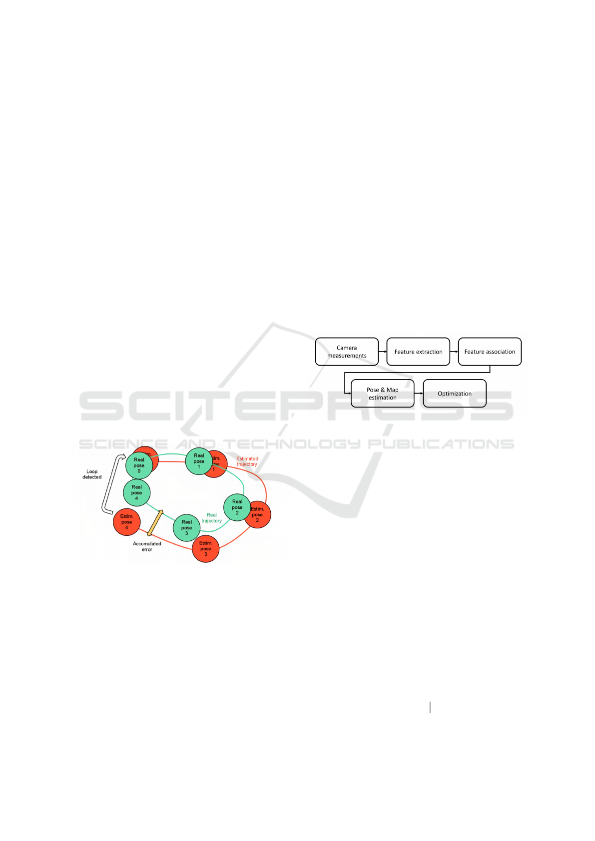
lating or drifting errors. An illustration of this accu-
mulating effect is given in Figure 1. To address this
issue, map refinement techniques, such as pose graph
optimization, can be used to significantly reduce the
drifting error. This is indicated by the white arrow.
However, in this work, bundle adjustment is chosen
as the optimization technique to refine the estimates
and reduce the error.
Figure 1: Illustration of the accumulating error. (Wong,
2014).
As said, our work relies on monocular visual
SLAM algorithms. In general, these algorithms can
be broken down into five major parts, as represented
schematically in Figure 2. The work carried out for
this paper can be situated in the ”Optimization” part.
The visual variant of SLAM has been a subject of ex-
tensive research and development over the years. The
inception of monocular SLAM can be traced back to
2007 when Davison introduced MonoSLAM (Davi-
son et al., 2007). This algorithm utilized an extended
Kalman filter (EKF) to achieve real-time localization
by leveraging large image patch features and sparse
prior scene knowledge. Although Kalman filter-based
odometry systems are relatively simple and elegant,
optimization-based methods have been introduced to
increase accuracy. Odometry systems based on bun-
dle adjustment optimization have been adopted with
great success, albeit at the cost of increased computa-
tional complexity (an increase that can be controlled
with a smart use of keyframe-based and sliding win-
dow optimization). VINS-Mono (Qin et al., 2018) is
a robust visual-inertial odometry estimation system
that maintains recent states of map points and cam-
eras in a sliding window, optimized with local bun-
dle adjustment. Visual features are tracked using KLT
and optical flow. ORB-SLAM (Campos et al., 2021)
uses ORB features and a descriptor-based approach
for matching, which is more expensive computation-
ally but can offer better long-term data association
performance.
Figure 2: Key components of a visual SLAM algorithm.
2.2 Bundle Adjustment
Bundle adjustment, often abbreviated as BA, can be
considered a general optimization technique for the
estimated trajectory and map. In robotics terms, it is
a state estimation technique used to jointly refine the
estimates of the 3D location of the observed points
and the camera poses. This refinement is performed
by minimizing the reprojection error, which expresses
the difference between the projection of the estimated
3D map points in the camera image and the actual
location in the image where the point is observed, as-
suming that the exact pose of the cameras and the co-
ordinates of the points in the environment are known.
By combining the data captured in several consecu-
tive frames, the estimates of the camera poses and the
World Coordinates of the observed features can be si-
multaneously optimized. Mathematically, the expres-
sion of the initial situation for a bundle adjustment
problem is given in (1):
u
v
w
= K · R ·
I
3×3
t
·
X
W
1
(1)
ICAART 2024 - 16th International Conference on Agents and Artificial Intelligence
214

The 3 × 1 column vector (u v w)
T
at the left-hand
side of this equation represents the three-dimensional
pixel coordinates of an observed point. Note that the
third component is added to express the vector in ho-
mogeneous coordinates. On the right-hand side, the
3 × 3 matrix K is the intrinsic matrix of the camera,
the 3 × 3 matrix R is the rotational matrix, and the
3 × 1 column vector t represents the translation of the
camera center. I
3×3
represents the identity matrix of
dimension 3. The final 4 × 1 column vector (X
W
1)
T
represents the observed 3D point in homogeneous
coordinates in the World Coordinate System.
Moreover, the residual r can be expressed as:
r =
x
y
−
u
w
v
w
(2)
where (x y)
T
represents the observed pixel coordi-
nates of a feature. These coordinates will be pro-
vided as input to the BA algorithm. The second
vector
u
w
v
w
T
is calculated from the estimated ho-
mogeneous coordinates of the point in the three-
dimensional WCS and represents the reprojection of
an observed point in the image plane. By changing
the values of K, R and t, these reprojected coordi-
nates will vary accordingly.
In essence, a bundle adjustment algorithm will per-
form a nonlinear least squares (NLLS) optimization
in order to minimize the sum of the squared residuals
r over all considered points and camera poses:
min
C,X
∑
|| u
i j
− π(C
j
, X
i
) ||
2
(3)
In (3), u
i j
represents the observations in pixel coor-
dinates. This is inherently equal to (x y)
T
defined in
(2). π(C
j
, X
i
) represents the projection of a point X
i
into the camera plane of camera C
j
. Hence, this term
corresponds to
u
w
v
w
T
defined in (2). Note that this
is a nonlinear operation.
3 METHOD
As a first building block, a pipeline to perform bun-
dle adjustment based on the measurements made by a
single agent is proposed. This is referred to as Single-
Agent Bundle Adjustment (SABA). We start with a
description of this algorithm, before moving on to the
Multi-Agent Bundle Adjustment (MABA) system.
3.1 Single-Agent Bundle Adjustment
As illustrated by (3), the first step is to reproject the
observed features in the camera plane. This can be
Figure 3: MABA algorithm pipeline.
easily achieved by multiplying the estimated World
Coordinates of the points with the camera pose matrix
T ∈ SE(3), then with the camera intrinsic matrix to
obtain the pixel coordinates that are ultimately used
to calculate the residual.
Once all features are transformed to the Pixel Co-
ordinate System (PCS), the actual bundle adjustment
is carried out using the Ceres library. This library al-
lows for the solution of NLLS problems using various
solution methods, such as the Gauss-Newton method
or the Levenberg-Marquardt algorithm. Optionally,
the resulting camera trajectory can be smoothed to
reduce the effect of outliers, caused by an incorrect
pose estimation. This will result in a smaller Abso-
lute Pose Error (APE) and Relative Pose Error (RPE)
between the estimated trajectory and the ground truth.
When calculating the optimal camera poses and point
locations in the map, the algorithm can be run in two
different modes. The most intuitive approach is to
run the algorithm in the so-called ’unbounded’ mode,
which imposes no additional constraints on the re-
fined parameters. While being the least constrained
problem, it might result in some camera positions be-
ing heavily displaced in order to minimize the global
cost function. To avoid this effect, which has a neg-
ative impact on the APE and RPE after alignment
with the ground truth, the algorithm can be run in the
’bounded’ mode. Now, the displacement of the cam-
era poses and the point coordinates is limited to avoid
huge outliers. In any of the three principal directions,
the maximal displacement of the camera positions is
clamped to [−δ, δ], where δ ∈ R
+
is a user-input pa-
rameter. Camera rotations and 3D point coordinates
are clamped in a similar manner.
While imposing additional constraints to the opti-
mization problem, this method tends to avoid having
great outliers, hence improving the alignment of the
estimated trajectory with the ground truth.
Multi-Agent Monocular SLAM
215

Figure 4: Illustration of point correspondences between images captured by different sequences. The colored lines connect
the matching features in the images.
3.2 Multi-Agent Bundle Adjustment
The goal of this algorithm is to combine the data from
multiple sequences such that the estimates of the cam-
era poses and the coordinates of the points are refined
jointly for these sequences. By relying on measure-
ments obtained with multiple agents, the uncertainty
of the estimates can be reduced, which should lead to
more accurate results.
A key component of our pipeline is the Scaled
Point Cloud Registration (SPCR) system that we use
to make the outputs of each agent’s SLAM system co-
herent. In fact, monocular SLAM suffers from scale
ambiguity. Moreover, the different sequences do not
share the exact same initial pose. Therefore, we need
to apply a Similarity transform (Sim(3): an SE (3)
transformation with an extra degree of freedom for
scale) to the poses and map points to make the monoc-
ular SLAM outputs of different agents coherent.
In Figure 3, the pipeline of the MABA algorithm
is presented. The first step will be to match the de-
scriptors of the points of the different sequences based
on a multi-dimensional distance metric. Once the
point correspondences are established correctly, the
SPCR is performed between the matching points in
order to estimate the rigid transformation parameters
that map the points observed by one sequence to the
reference frame of the other.
3.2.1 Descriptor Extraction and Matching
Every point considered by ORB-SLAM2 is given a
32-element descriptor vector. These vectors can be
used to establish point correspondences by calculat-
ing the minimum distance between the points seen in
different sequences. As ORB uses binary descriptors,
the Hamming distance is considered as a metric in this
article.
To increase the robustness of the point matching,
Lowe’s ratio test (Lowe, 2004) is implemented, which
discards ambiguous matches. In a practical applica-
tion, the distance between the closest and the second-
closest neighbor for a certain query descriptor is of-
ten very small. Consequently, incorrect matches often
occur whenever there is noise in the considered im-
ages. The idea behind this ratio test is that a match is
only accepted if the ratio of the distance to the closest
and second closest neighbor is smaller than a certain
threshold:
Accept if r =
d
NN
d
SNN
< threshold (4)
where d
NN
represents the minimal (Hamming) dis-
tance (Nearest Neighbor) between a query descriptor
and all descriptors against which it is matched. d
SNN
represents the second lowest distance (Second Near-
est Neighbor). If this ratio is smaller than the accep-
tance threshold, one can assume that the matching has
overcome the effects of noise or other sources of in-
consistencies in the calculation of the descriptors.
An example of point correspondences between
two images captured by different sequences is pro-
vided in Figure 4.
3.2.2 Pose Transformation Based on Established
Point Correspondences
We describe the Scaled Point Cloud Registration
(SPCR) system that we use to make the outputs of
each agent’s SLAM system coherent. Since the cam-
era poses and the estimated point positions for each
agent are expressed relative to their first camera pose,
considered as the origin, the different sequences are
often expressed in totally different coordinate frames,
making it difficult to compare the poses or the points
in an absolute way. To overcome this issue, the rigid
pose transformation parameters are estimated from a
set of matching points. By definition, these match-
ing points should have the exact same coordinates
when expressed in a common coordinate frame. This
ICAART 2024 - 16th International Conference on Agents and Artificial Intelligence
216
knowledge can be used to estimate a Sim(3) trans-
form, i.e., 3 × 3 rotation matrix R, a 3 × 1 translation
vector t and a 3 × 1 scale vector s that map the points
from one coordinate system to the other:
X
′
1
= diag([s, 1])·
R t
0 1
·
X
1
(5)
where X and X
′
represent the point coordinates in the
original reference frame and the transformed coordi-
nates, respectively.
The results of the SPCR algorithm for the point
correspondences visualized in Figure 4 are presented
in Figure 5. There is indeed an apparent initial scale
difference between the estimated point coordinates
for the two sequences. However, after the transforma-
tion, both sets of points coincide almost perfectly. In
this figure, the source points represent the points that
should be transformed to a different coordinate sys-
tem. The target points are the points from the other
sequence with which the source points match.
Finally, the estimated transformation can be ap-
plied to the camera poses as well in order to transform
them to a common reference frame.
Figure 5: Illustration of the SPCR algorithm.
3.2.3 Combination of Keyframes and Points in a
Common Data Structure
Once all data is transformed to the same reference
system, a common data structure can be created for
the different sequences. This way, the multi-agent
problem is translated to one larger optimization prob-
lem, that involves the data of multiple sequences. The
observations of matched points are combined, while
unique points are individually added to the optimiza-
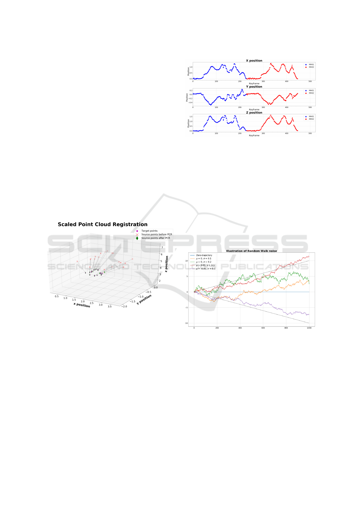
tion problem. An illustration of the combined trajec-
tory of sequences MH01 and MH02 is given in Figure
6. Notice the similarity in scale between the two se-
quences, enforced by the SPCR algorithm.
Figure 6: Resulting combined trajectory after SPCR.
4 EXPERIMENTS AND
DISCUSSION
As explained in the introduction, ORB-SLAM2 is
used to obtain the initial estimates of the camera poses
and the locations of the points in the created map for
each agent. Our system is evaluated on the EuRoC
dataset (Burri et al., 2016). Since ORB-SLAM2 re-
sults do not typically exhibit significant drifting errors
(longer data sequences would be needed to better ob-
serve accumulating errors), our proposed system will
be validated through the deliberate addition of noise.
Figure 7: Illustration of the random walk noise.
Two different noise models are used to distort
the original estimates. First, a zero-mean Gaussian
noise is applied to the data, for which the effects
of the standard deviation of the applied noise on
the obtained results are analyzed. In a second set
of experiments, a random walk noise is applied to
the camera positions. This simulates the effect of an
accumulating error, which results in a more realistic
noise. This effect is illustrated by the red and purple
curves in Figure 7.
In Table 1, an overview of the different scenarios
is given.
Multi-Agent Monocular SLAM
217
Table 1: Overview of the considered scenarios.
Scenario Noise type BA type
Discussed
noise parameter
Affected
quantity
Scenario 1 Gaussian Motion-only σ Camera positions
Scenario 2 Gaussian Motion-only σ Point coordinates
Scenario 3 Gaussian Full σ
Camera positions
Point coordinates
Scenario 4 Random Walk Motion-only
µ
σ
Camera positions
Scenario 5 Random Walk Motion-only σ Point coordinates
Scenario 6 Random Walk Full σ Point coordinates
4.1 Results for the SABA Algorithm
In Figure 8, the results of a sensitivity analysis of the
unbounded SABA algorithm are given for scenario
1. Note that for this scenario, the algorithm is run in
the motion-only mode, indicating that only the cam-
era poses are refined. Especially for sequences MH01
and MH02, it is clear that the algorithm does not per-
form accurately for values of σ > 0.15. In these cases,
the APE after optimization is larger than before, due
to the presence of extreme outliers in the optimized
camera trajectory. By applying the smoothing filter,
which reduces the effect of these outliers, the APE is
indeed considerably smaller.
Figure 8: Results of the unbounded SABA algorithm for
scenario 1.
The estimates can be further improved by apply-
ing the bounded SABA algorithm, as shown in Fig-
ure 9. In all of our experiments, the bound parameter
is set to δ = 0.3. Now, even for the largest value of
σ, the APE after optimization is significantly smaller
than the APE of the noisy trajectory, which suggests
the refined trajectory is closer to the ground truth after
alignment.
4.2 Results for the MABA Algorithm
Finally, the bundle adjustment algorithm can be ap-
plied to the common data structures as explained in
Section 3.2.3. To guarantee a maximal overlap be-
tween the sequences, a combination of sequences
MH01 and MH02, and sequences MH04 and MH05
has been chosen in this article. For each of these, the
Figure 9: Results of the bounded SABA algorithm for sce-
nario 1.
coordinate system and scale of the first sequence, re-
spectively MH01 and MH04, have been chosen as a
reference.
A comparison of the performance of the SABA
and MABA algorithm for scenario 1 is visualized in
Figure 10. There, it is clear that the resulting APE is
lower for the unbounded MABA algorithm than for
the single-agent variant for the same value of σ, in-
dicating that the extension to multiple agents indeed
has a positive effect on the optimized trajectory. How-
ever, for the bounded algorithm, the difference be-
tween SABA and MABA is negligible. This is due
to the higher level of limitation of the mathematical
problem, which reduces the potential to increase the
accuracy of the estimates by applying an optimization
algorithm.
For scenario 3, which considers the ’full’ bundle
adjustment algorithm, results tend to show a trend
similar to scenario 2. This is visualized in Figure
11. Now, the improvements are especially apparent
when the unbounded algorithm is applied to sequence
MH01, at values of σ > 0.09. For the bounded
algorithm, the difference is again negligible.
Notice that while the results obtained with the
MABA algorithm are generally better than for the
SABA algorithm, the computation time is signifi-
cantly (∼10×) larger for the MABA algorithm, com-
puting the optimized poses and points for all agents
simultaneously.
5 CONCLUSION
This article discusses a bundle adjustment pipeline to
improve the estimated camera poses and locations of
points in the map, either based on measurements pro-
vided by a single agent or by combining the mea-
surements of multiple agents. For a setup involving
monocular visual SLAM, it is shown that the accuracy
of the estimates, after the deliberate addition of noise,
ICAART 2024 - 16th International Conference on Agents and Artificial Intelligence
218
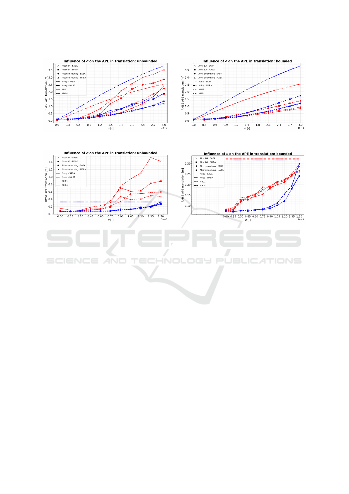
(a) (b)
Figure 10: Scenario 1: Comparison of the results of the SABA and MABA algorithm for the APE in translation.
(a) (b)
Figure 11: Scenario 3: Comparison of the results of the SABA and MABA algorithm for the APE in translation.
improves when the data of multiple agents are con-
sidered. However, a trade-off between the improved
accuracy and an increase in computation time should
always be considered.
6 FUTURE WORK
In this article, a multi-agent bundle adjustment
pipeline has been proposed for monocular visual
SLAM systems. In further research, this could be ex-
tended to integrate the data of other sensors, such as
GPS, IMU, or lidar, to improve the accuracy of the
estimates. Moreover, an analysis of the scalability
of the algorithm could be performed. As explained,
the computation time increases with a factor 10 when
the algorithm is expanded to consider two indepen-
dent sequences. Although the extension to additional
agents should be straightforward, computation time
might become an issue when too many agents are
considered. Therefore, future research could focus
on speed improvements for descriptor matching and
the solution of the nonlinear least-squares optimiza-
tion problem. A final suggestion would be to per-
form an analysis of the parameters of the Ceres solver.
Fine-tuning these parameters, such as the type of lin-
ear solver, the step size of the Levenberg-Marquardt
solver, or the type of loss function, could significantly
impact the results. Conducting a comprehensive sen-
sitivity analysis of these parameters across diverse
datasets would therefore be valuable to determine the
best settings for different scenarios.
REFERENCES
Burri, M., Nikolic, J., Gohl, P., Schneider, T., Rehder, J.,
Omari, S., Achtelik, M., and Siegwart, R. (2016). The
euroc micro aerial vehicle datasets. The International
Journal of Robotics Research.
Campos, C., Elvira, R., Gomez, J. J., Montiel, J. M. M.,
and Tardos, J. D. (2021). ORB-SLAM3: An accu-
rate open-source library for visual, visual-inertial and
multi-map SLAM. IEEE Transactions on Robotics,
37(6):1874–1890.
Davison, A. J., Reid, I. D., Molton, N., and Stasse, O.
(2007). Monoslam: Real-time single camera slam.
IEEE Transactions on Pattern Analysis and Machine
Intelligence, 29:1052–1067.
Lowe, D. (2004). Distinctive image features from scale-
invariant keypoints. International Journal of Com-
puter Vision, 60(2):91–110.
Mur-Artal, J., Montiel, R., and Tard
´
os, J. (2017). Orb-
slam2: an open-source slam system for monocular,
Multi-Agent Monocular SLAM
219

stereo and rgb-d cameras. IEEE Transactions on
Robotics, 33(5):1255–1262.
Qin, T., Li, P., and Shen, S. (2018). Vins-mono: A robust
and versatile monocular visual-inertial state estimator.
IEEE Transactions on Robotics, 34(4):1004–1020.
Wong, W. (2014). Autonomous 3d mapping and exploration
using a micro aerial vehicle. pages 138–142.
ICAART 2024 - 16th International Conference on Agents and Artificial Intelligence
220
