Automatic Viewpoint Selection for Interactive Motor Feedback Using
Principle Component Analysis
Florian Diller
1 a
, Alexander Wiebel
1 b
and Gerik Scheuermann
2 c
1
UX-Vis group, Hochschule Worms University of Applied Sciences, Germany
2
BSV group, Universit
¨
at Leipzig, Germany
Keywords:
Automatic Viewpoint Selection, Automatic Perspective, Visual Movement Feedback.
Abstract:
We present a novel method to automatically select a viewpoint optimized for the interactive display of a
physical exercise which is shown using a human skeleton-like avatar with additional visual motor feedback.
Expressive viewpoints are crucial for the users to be able to understand and interactively adapt to the feed-
back in all its spatial aspects. Selecting camera perspectives for these viewpoints can be challenging when
the presentation includes specific visual feedback cues in addition to the instantaneous pose, as many different
requirements have to be taken into consideration in this case. The users continuously correcting their move-
ments according to the visual real-time feedback represents a special case of human-computer interaction.
Our algorithm employs principal component analysis (PCA) to determine informative viewing directions for
the overall pose and specific feedback cues shown at different joints. The final viewpoints are synthesized
from the obtained directions in a per-frame manner. To evaluate our method we conducted a user study with
39 participants. They were asked to choose from four exercise videos with motor feedback generated by the
presented method and three competing existing approaches. Additionally, to validate our approach’s assump-
tions, we asked the participants to freely choose a viewpoint, which they considered optimal for the provided
motor feedback. The results of the study show that our algorithm was most frequently chosen as being the
most informative. Furthermore, our method proved much faster than previous viewpoint selection methods, as
it does not require information about upcoming frames. This makes our approach most suitable for real-time
and interactive applications.
1 INTRODUCTION
In our modern times, learning new skills is essential.
May it be in recreational sports, physical therapy, or
professions, skill learning is omnipresent. In addition,
to improve the learning effect, skill learning can be
supported by modern interactive technology. Partic-
ularly, in motor skill training supported by mixed re-
ality technologies, interactive visual corrective feed-
back using motion tracking plays an increasingly im-
portant role as we showed in previous work (Diller
et al., 2022). Feedback is in this context used to teach
people how to execute specific body movements cor-
rectly without the need for continuous supervision by
highly qualified human trainers. Especially in physio-
therapy and physical exercise, executing movements
a
https://orcid.org/0000-0001-7421-750X
b
https://orcid.org/0000-0002-6583-3092
c
https://orcid.org/0000-0001-5200-8870
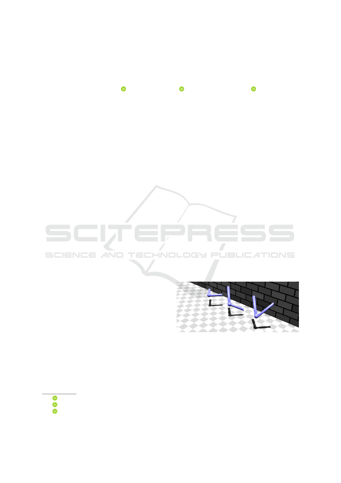
Figure 1: Example for the importance of viewpoint selec-
tion: Three different angles at joints have the same shadow
if projected to the ground. This implies they are also look-
ing the same when viewing them from above. Illustration
inspired by Nundy et al. (Nundy et al., 2000).
correctly is important to achieve the desired positive
effects and avoid injuries. Furthermore, the context
of physiotherapy and strength training involves con-
trolled repetitive movements, which makes it possible
to give clear feedback and identify typical mistakes.
If automatically generated feedback is rendered
and displayed in real-time, a good viewpoint is cru-
350
Diller, F., Wiebel, A. and Scheuermann, G.
Automatic Viewpoint Selection for Interactive Motor Feedback Using Principle Component Analysis.
DOI: 10.5220/0012308700003660
Paper published under CC license (CC BY-NC-ND 4.0)
In Proceedings of the 19th International Joint Conference on Computer Vision, Imaging and Computer Graphics Theory and Applications (VISIGRAPP 2024) - Volume 1: GRAPP, HUCAPP
and IVAPP, pages 350-361
ISBN: 978-989-758-679-8; ISSN: 2184-4321
Proceedings Copyright © 2024 by SCITEPRESS – Science and Technology Publications, Lda.

Figure 2: Feedback for the same angle viewed from different perspectives. Two different feedback cues: circular sector (left),
and arrow (right). From left to right: Perfectly visible, visible, and hardly visible feedback. Shadows demonstrate that also
for the feedback geometry, i. e. not only for the angle itself, but the viewpoint influences the perception.
cial to allow users to correctly interpret, understand,
and finally execute what is shown. Especially, the
positions of the joints of the human skeleton and
the angles between the respective limbs or bones are
most relevant regarding the interpretation of executed
movements. However, particularly for angles, the per-
ception is highly dependent on the perspective. Previ-
ously analyzed by Nundy et al. (Nundy et al., 2000),
angles are difficult for humans to perceive. That is es-
pecially true if rendered by a computer because a pro-
jection to the screen area is necessary and this projec-
tion can distort the angles as seen in Figure 1 and Fig-
ure 2. Regardless, while viewed in stereoscopy (e.g.
real world or head-mounted displays), depth percep-
tion can help to interpret angles, and yet unfortunately
that is not true to the same extent with a monoscopic
rendering of an angle. However, the perception of
angles is not the only obstacle faced when providing
rendered feedback. Occlusion can also limit the un-
derstanding of the human pose in space. In particular,
self-occlusion of the human avatar can hide limbs be-
hind other body parts. Likewise, if visual cues are ren-
dered as feedback, they can be occluded by the avatar
or by themselves as seen in figures 2 and 3. How-
ever, good visibility of the visual cues is central when
giving corrective feedback. We recently showed the
prevalent use of visual cues as corrective feedback for
skill learning with mixed reality in the current litera-
ture (Diller et al., 2022).
Nevertheless, feedback and visual cues in particu-
lar are not considered by current approaches for view-
point selection regarding human motions and actions.
Many methods found in the literature are computa-
tionally expensive and not real-time capable. In con-
trast, this paper gives insights into what factors are
important when selecting viewpoints for movement
correction and explains how these factors can be used
to automatically select a viewpoint. Using principal
component analysis (PCA), we present a real-time ca-
pable algorithm to find a continuous optimal camera
perspective for avatars of an actual motion together
with a target motion and corresponding feedback. We
validate the underlying assumptions and evaluate our
methods in comparison to methods found in the lit-
erature in a user study. In addition, the results show
that our method is not only preferred by users but also
computationally the fastest.
2 RELATED WORK
As Bouwmans et al. (Bouwmans et al., 2018) showed
for robust PCA, there are various uses for PCA in
the field of visual computing. For example, Skaro
et al. (Skaro et al., 2021) present a method to re-
duce crosstalk errors, which are commonly present in
marker-based motion tracking.
Several works discuss approaches of viewpoint
selection for human actions or movements. For in-
stance, Rudoy et al. (Rudoy and Zelnik-Manor, 2011)
create a volume from different frames to select the
best physical camera for television broadcasts or sim-
ilar applications. In contrast, Kiciroglu et al. (Ki-
ciroglu et al., 2020) provided an algorithm to predict
the pose estimation accuracy to navigate a drone to
the calculated position. Additionally, Shi et al. (Shi
et al., 2012) provide an algorithm to calculate the best
viewpoint using the Kinematics Significance Based
Saliency to orient figures and objects preferring views
that show most of the protruding features.
Wang et al. (Wang et al., 2019) achieve the selec-
tion of a single viewpoint of an action sequence utiliz-
ing information theory and deep reinforcement learn-
ing. Likewise, Choi et al. (Choi et al., 2012) extract
key frames from motion data to generate a sequence
of stick figures to represent the initial motion data.
Ishara et al. (Ishara et al., 2015) calculate the best
camera position to navigate a robot with a camera
Automatic Viewpoint Selection for Interactive Motor Feedback Using Principle Component Analysis
351
mounted on top. For that purpose, the so-called Joint
Mutual Occlusion (JMO) is calculated by summating
the angles between adjacent joints and the potential
viewpoint. Concrete information like joint positions
can be utilized, as the approach uses the information
of a motion tracking camera. As a result, the work
exhibits a close relation to our work, since we include
motion-tracking data as well.
Similarly, Kwon et al. (Kwon et al., 2020) use
joint positions to calculate the best angle for skele-
tons utilizing projected limb lengths as well as 2D and
3D bounding boxes. Subsequently, the three metrics
are combined in a weighted error function. Although
these two approaches select camera positions for hu-
man poses automatically, they are not sufficient for
visual feedback, as the skeleton can occlude the feed-
back. In addition, feedback provided can be difficult
to perceive as analyzed by Nundy et al. (Nundy et al.,
2000) and discussed in section 1.
The last two approaches mentioned -(Ishara et al.,
2015) and (Kwon et al., 2020) - were compared to
our method in the subsequent user study, as only these
methods were possible to apply to human figures with
feedback. For more information see subsection 3.2.
Another topic related to the viewpoint selection of
an executed movement is camera path computation.
For instance, Kwon and Lee (Kwon and Lee, 2008)
describe how a smooth camera path can be computed
using the area traversed by a movement when pro-
jected on the screen. Additionally, their method also
considers occlusion.
Yeh et al. (Yeh et al., 2011) create smooth, aes-
thetic camera paths using a greedy-based tree traver-
sal approach. In contrast, Assa et al. (Assa et al.,
2005) summarize actions using still images. Conse-
quently, that requires the selection of key poses within
the motion.
Assa et al. (Assa et al., 2008) present a method to
compute a camera path and give an overview of hu-
man actions. That involves among other indicators the
third eigenvector generated by PCA of the joint coor-
dinates as we do, as explained in section 4. However,
their use case varies drastically. As they are comput-
ing camera paths, it is acceptable to involve camera
cuts. In contrast, we avoided this in our approach, as
the exercise repetitions are short, so cuts in the camera
movement are comparatively irritating to the viewers.
Furthermore, the work of Assa et al. is action-based.
Our work instead is feedback-based. That requires
additional measures because our method must ensure
the feedback is visible to the user. Lastly, their ap-
proach is not able to perform in real-time, as it is com-
putationally expensive and requires the whole motion
sequence for computation.
Figure 3: Skeleton of a human pose with feedback from two
perspectives. Two visual feedback cues are shown: circular
sector and additional avatar (here skeleton). The feedback
is hardly visible from the perspective on the left.
Figure 4: Measure for the self-occlusion of the skeleton by
Ishara et al. (Ishara et al., 2015): Joint Mutual Occlusion.
3 PERSPECTIVE
CONSIDERATIONS
In the literature, we do not find absolute rules for good
perspectives. However, we can extract several criteria
and hints on what might be considered a good view-
point. That includes both empirically established user
preferences and logical argumentation.
3.1 General Considerations
Polonsky et al. (Polonsky et al., 2005) identified seven
measurable view descriptors. Yet they concluded, that
finding a general way to provide a good view of an ob-
ject is challenging. None of the seven view descrip-
tors alone gives a general measure of viewpoint qual-
ity. However, there are some clues on how to treat
certain objects. For example, Zusne (Zusne, 1970)
empirically showed that if the object has eyes and a
face, humans prefer to view it frontally.
As there is no general description of a good view,
we need to define what characterizes a good view-
point for our use case. In the following explana-
tions, we often use the metaphor of a virtual cam-
era, common in rendering to describe the viewpoint
HUCAPP 2024 - 8th International Conference on Human Computer Interaction Theory and Applications
352

and viewing direction. Following Zusne’s (Zusne,
1970) findings, we prefer an approximately frontal
view of the human pose, i.e. views where the vir-
tual camera is pointed towards the front of the pose
rather than a view from behind. Moreover, the cam-
era up-vector should be the same as the world up-
vector to avoid confusing the viewers since this is
the biologically common way for humans to perceive.
Additionally, we also want to limit the occlusions of
the avatars showing the movement execution. Lastly,
in our use case, we provide feedback through visual
cues for correcting movement or poses and thus want
this feedback to be visible. This means the feedback
should not be occluded by the avatar or itself and
should be as perpendicular to the view direction as
possible.
When selecting perspectives for human motions
and corresponding feedback, dependencies of differ-
ent body parts are relevant. In particular, the limbs
are hierarchically linked. Therefore, when we, for ex-
ample, move the upper arm, the lower arm and hand
will follow. Consequently, perspectives for such mo-
tions would ideally consider a hierarchical drill-down
mechanism to prioritize along the hierarchy.
3.2 Methods from Current Literature
There are several methods to provide a good view
of a human figure and limit self-occlusion as we de-
scribed in section 2. For instance, the JMO of Ishara
et al. (Ishara et al., 2015) considers the angle α be-
tween two joints and the viewpoint, as seen in Fig-
ure 4. Subsequently, the angles α
nm
between joints n
and m are summed up and normalized, where n, m ∈ N
and n ̸= m, and where N represents the number of
joints. Combinatorically this creates
N!
2(N−2)!
calcu-
lations of α (Charalambides, 2002).
The work of Kwon et al. (Kwon et al., 2020) re-
sults in a weighted sum of the three metrics normal-
ized limb length, normalized area of a 2-D bounding
box, and normalized visible area of a 3-D bounding
box. However, this, in their case, best-performing al-
gorithm is designed for still poses and requires calcu-
lation for each pose. As a consequence, in the case
of videos, this would require a recalculation for each
frame. Furthermore, they present an algorithm with-
out recalculating the weights for each frame, which is
the sum of the three metrics without weights.
PCA is often used to reduce dimensions in data
sets for machine learning (Sorzano et al., 2014). The
principal components represent the independent main
directions in which the data points spread. If we han-
dle spatial data, three independent directions are in-
volved. The first two principal components represent
the main spread directions. Additionally, the third
component offers a good view direction, or perspec-
tive, to observe the data points, because it is perpen-
dicular to the first two. This is equivalent to a dimen-
sion reduction from three to two, as the rendered im-
age of 3D objects only features two dimensions. Assa
et al. (Assa et al., 2008) use this method in their work
to calculate camera paths (see section 2). For more
practical information on how we apply this see sec-
tion 4.
4 METHODOLOGY
The existing literature as presented in section 2 does
not yet provide an optimal viewpoint calculation for
human movement with visual feedback as it is suit-
able for skill learning. Most approaches are optimized
for human actions. Consequently, feedback provided
for the action could not be visible from the action-
optimized viewpoint. In the following, we guide you
through the steps of our computationally inexpensive
way to calculate a viewpoint for human actions with
feedback. Equation 1 shows the calculation of our
view direction⃗v
d
:
⃗v
d
= w ·⃗v
S
+
N
∑
n=1
(∆
n
− δ
0
) ·⃗v
Fn
(1)
To calculate⃗v
d
we require the following variables:
w is a weight to balance out the impact of the view to-
wards the whole skeleton and towards the feedback,
the vector ⃗v
S
represents the viewpoint optimized for
all joint coordinates (i.e. the actual skeleton), N is the
number of joints exceeding a given deviation thresh-
old δ
0
, ∆
n
is the deviation of a joint to the intended tar-
get position, δ
0
is a constant deviation threshold, and
lastly⃗v
Fn
is the view direction optimized for the feed-
back, i.e. the deviating joint J
n
and its corresponding
joints as seen in Figure 5. We do not consider rota-
tions in particular, as they inevitably lead to a distance
deviation as well.
Some motion capture systems present data as
three-dimensional joint coordinates (see section 5 for
our data acquisition conditions). When we conduct
a PCA over this point cloud of joint coordinates, the
first two eigenvectors ⃗e
1S
and ⃗e
2S
represent the two
main spatial dimensions the points spread out in. The
third eigenvector ⃗e
3S
=⃗v
S
, which is perpendicular to
the first two, then gives a good view direction ⃗v for
all joints, as explained in subsection 3.2. Because the
point cloud representing the whole skeleton is most
spread out in the horizontal and vertical directions of
the captured camera picture, the view direction ⃗v
S
is
optimal for understanding and overall movements and
Automatic Viewpoint Selection for Interactive Motor Feedback Using Principle Component Analysis
353

poses. This method is also seen in Assa et al. (Assa
et al., 2008).
As we want to focus on the feedback for the de-
viations of the exercises, we have to consider the de-
viating joints. For this purpose, we selectively ap-
ply viewpoint calculation. We conduct a PCA of the
actual and the target joint coordinates and the corre-
sponding parent joint coordinates as seen in Figure 5
for joints J
n
,n ∈ [1..N] exceeding a deviation thresh-
old δ
0
of the distance between the actual to the target
joint location. Consequently, the eigenvector ⃗e
3Fn
of
the PCA is orthogonal to the plane optimally display-
ing joint J
n
, its parent, as well as the corresponding
optimal joint position and its parent. This can be seen
in Figure 5, where the considered joint J
n
is shown
in red, the optimal joint position in orange, and the
corresponding parent joints are depicted in blue.
This gives us the view direction ⃗e
3Fn
= ⃗v
Fn
for
the feedback of joint J
n
, where n ∈ [1..N] is an in-
dex out of the number N of joints exceeding the de-
viation threshold δ
0
to their target counterparts. In
Equation 1, the multiplication of ⃗v
Fn
with ∆
n
(minus
the threshold δ
0
) increases the impact of joints with
higher deviations. This also naturally promotes a kind
of hierarchical drill-down mechanism (see section 3),
since lower hierarchy joints usually have a higher ab-
solute deviation, as they are impacted by the devi-
ations of the higher hierarchy joints (intercept theo-
rem). We subtract the threshold δ
0
to ensure a contin-
uous camera movement so that the impact of deviat-
ing joints continuously increases (sets in) from zero.
The sum of all ⃗v
Fn
represents a feedback-optimized
view direction for all joints exceeding the deviation
threshold.
The skeleton-optimized view direction is
weighted with the constant w to impact the balance
between optimizing for the skeleton and feedback.
Values of δ
0
= 50 and w = 3δ
0
= 150 yielded the
best results in our experiments. This holds several
implications:
• The view directions (eigenvectors) resulting from
the PCA are normalized. That means they have a
length of 1. In the virtual 3D space we applied a
scale of 1 unit = 1 mm. Consequently, the devia-
tion threshold δ
0
is corresponding to 50 mm.
• For the feedback view direction ⃗v
Fn
of a single
joint to have the same impact as the view direction
for the entire skeleton (⃗v
S
), the joint would need
to have a deviation of 200 mm. This consists of
a 50 mm minimal threshold plus 150 mm of the
weight.
• The deviations of several joints together can ex-
ceed the threshold of 150 mm to have the same
impact on the view as the skeleton as a whole.
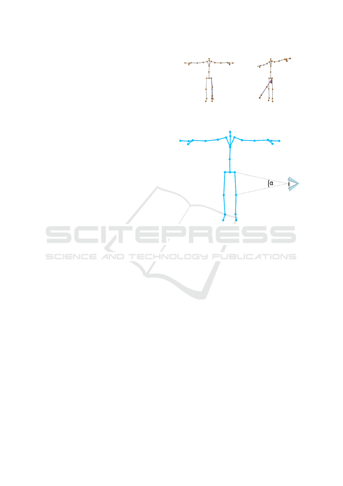
Figure 5: If Joint J
n
(in red) deviates from the target posi-
tion, we additionally include the corresponding target joint
(in orange) and its parents (in blue) in the PCA. The eigen-
vector ⃗e
3n
then gives us an optimal view direction ⃗v
Fn
of
the feedback. It is perpendicular to the plane defined by the
eigenvectors⃗e
1n
and⃗e
2n
. This plane does not interpolate the
considered joints, but rather approximates their distribution.
• If multiple joints do not exceed the 50 mm min-
imal threshold the skeleton still has an impact of
100% and the viewpoint is optimized for just the
skeleton.
• Because we consider the absolute deviation (in-
stead of relative to the parent), lower hierar-
chy joints are dependent on their parent joints.
This creates a hierarchical drill-down mechanism
as explained in subsection 3.2, where the joints
closer to the torso have a higher impact.
To obtain the viewpoint for the virtual camera, we
subtract the normalized view direction⃗v
d
from the lo-
cation of the focus point, which will be centered in the
rendered frame (in our case the joint representing the
pelvis location, since it is a central point of the body).
With the multiplication of a constant, the distance to
the focused point can be set. The digital equivalent of
2 m held the best results in our case, as all exercises
were in frame at this distance. This, however, depends
highly on the settings (e.g. focal length) of the virtual
camera chosen for the intended application.
If ⃗e is an eigenvector, c ·⃗e is also an eigenvector,
for all c ̸= 0 (Borisenko and Tarapov, 1979). Con-
sequently, −⃗v
d
, the flipped eigenvector of ⃗v
d
, is also
viable as a view direction. Therefore we are free to
choose which of the eigenvector orientations we use
as our view direction. For the initial calibration, we
can select the direction resulting in a more frontal
view of the avatar, since this is the predominantly pre-
ferred view (Zusne, 1970). For every further frame,
we select the direction (out of the two) whose angular
difference from the direction in the previous frame is
smaller, as we want a smooth camera movement.
Although using the third eigenvector of the PCA
results in a smooth camera movement, the camera
HUCAPP 2024 - 8th International Conference on Human Computer Interaction Theory and Applications
354

tends to rotate around the avatar. Thus, the findings
of Zusne (Zusne, 1970), who stated humans prefer a
frontal view, are contradicted. Hence, we projected
view angles from behind to the frontal plane to solve
this issue. This bypasses the predominantly small
number of frames that feature a view from behind and
shows a view from the side. The camera view is only
slightly and very briefly affected by the projection.
Because the existing view selection approaches
have foci different from ours, they rely on solving
an optimization problem. As a consequence, often
an algorithm iterates over a limited number of poten-
tial viewpoints, choosing the one with the best score.
This either yields a costly high number of iterations or
an erratic camera motion because the number of po-
tential viewpoints is too small. Additionally, the best-
scoring viewpoints in consecutive frames might be far
from each other, which again results in inconsistent
camera movements. However, our method provides
a continuous camera movement, as the PCA compu-
tations are conducted for continuously moving point
clouds, and none of the operations in Equation 1 com-
promises consistency.
In our exercise recordings, there were no cases
where a null vector arose from our calculations. Ad-
ditionally, we assessed stability regarding the PCA,
as the camera view could flip if the second and third
eigenvectors are approximately of the same length
and deviate slightly. This was not the case in our ex-
periments.
5 EXPERIMENTAL SETUP FOR
EXERCISE RECORDING
The poses and motions used throughout this paper
were recorded using a Microsoft Azure Kinect 3D
camera (Microsoft Development Team, 2018). Its
computer vision capabilities deliver spatial coordi-
nates of several joints of the human body it perceives.
In the following, the term joint is rather defined as bi-
ological points of interest than referring to the usual
medical definition of joints (Microsoft Development
Team, 2018).
In the following, we describe the conditions that
achieved optimal positioning of the subject in our
case: The camera was elevated to a height of about
140 cm with the help of a tripod. It was placed at a
distance of about 280 cm from the posing subject. The
subject is about 190 cm tall. This gave us stable track-
ing and a clear frame for recording the poses. For our
recordings, we discarded the joints of the eyes, ears,
and nose as we found that these are too imprecise and
they are irrelevant for pose correction in motor skill
training. This left us with 26 joints. We compared
two separate executions of the same exercise — an
ideal and current execution — and showed corrective
visual feedback cues to motivate the human user to
decrease the difference and execute the motion cor-
rectly. For further information on the visualization of
avatars see subsection 5.1.
Subsequently, a set of example exercises was de-
veloped. This was done so various exercises and devi-
ation combinations were included. We then compared
each of these exercises to the corresponding counter-
part with deviation from the correct form (see sub-
section 5.2). The methods used to create a matching
overlay of two exercises exceed the scope of this pa-
per. We often see, for example, Dynamic Time Warp-
ing fulfilling that role throughout literature (e.g. (Su,
2013), (Ant
´
on et al., 2015) and (Saenz-de Urturi and
Soto, 2016)).
5.1 Exercise Visualization
To visualize the actual motion we used an abstract
avatar, and for the target motion, a skeleton is dis-
played as seen in Figure 6. The visualization of the
skeleton displayed in green corresponds to the joints
recorded by the 3D camera (Microsoft Development
Team, 2018) as mentioned in section 5. We used two
different avatar visualizations to better distinguish the
actual movement from the target movement. This also
supports users with color vision deficiency, as the dif-
ferences between the avatars are made clear by shape,
not by color. The abstract avatar occludes more of it-
self and its background and visualizes fewer joint po-
sitions than the skeleton, as the fingertips and thumbs
Figure 6: Example of the avatar and feedback used in the
user studies. The white opaque avatar shows the actual
movement, and the green transparent avatar shows the tar-
get movement.
Automatic Viewpoint Selection for Interactive Motor Feedback Using Principle Component Analysis
355

(a) Bench press (b) Biceps curl A (c) Lateral raises (d) Shoulder press (e) Bend over row (f) Biceps curl B
Figure 7: Example exercises with deviations as described in subsection 5.2.
are integrated into the hand. Yet, for the optimization
of the viewpoint, all joints are included in the calcu-
lations. The visualizations in this paper are just used
for demonstrative purposes and are not the research
subject. We focus on viewpoint selection, where the
form of visualization plays a subordinate role.
5.2 Example Exercises
To evaluate our method (see section 6) and compare
it to approaches found in existing literature, we chose
four still poses to establish basic assumptions and
six moving exercises with corresponding deviations
from the ideal form to evaluate different methods of
viewpoint selection. The deviations were chosen to
be typical mistakes for the exercises considered. We
intended to find a selection of various exercises and
deviations to evaluate the methods objectively. That
means we selected the poses and exercises so that
different movement and feedback directions are rep-
resented in the exercises. When performing lateral
raises, for example, the arms are moved laterally away
from the body, whereas, in a biceps curl, the arms
move in front of the body (see Figure 7). We also
included an exercise with different deviations (biceps
curls A and B).
Selecting a viewpoint for videos could be seen
as selecting a continuous viewpoint for still poses in
each frame. To confirm our underlying assumptions
of viewpoint quality (see section 3) we chose four rep-
resentative still poses. In particular: Standing (stan-
dard anatomical position), squatting, bending down,
and bench press. In section 6 we explain in detail how
we let users select viewpoints and validate the results.
In the domain of physiotherapy and strength train-
ing many repetition-based exercises exist. We se-
lected the following six exercises with deviations (see
Figure 7 for visualization of the exercises): Bench
press (Deviation: Arms too wide), Lateral raises (De-
viation: Arms asymmetrical), Bend over row (Devi-
ation: Elbows tucked in), Shoulder press (Deviation:
Arms asymmetrical), Biceps curl A (Deviation: Rep-
etition only half executed), and Biceps curl B (Devia-
tion: Elbows do not stay stable).
6 EVALUATION
For the evaluation of our method, we conducted a user
study. The user study was structured in three sections.
Viewpoint Selection. We intended to confirm our as-
sumptions of user preferences for the views regarding
our use case and compare it to the existing literature
(primarily (Zusne, 1970)). For this purpose, we asked
the users to choose the viewpoint for still poses. Feed-
back was not present in this section, as we wanted to
evaluate the method for only the motions first. As
a continuous camera movement for videos selects a
viewpoint for a still pose in each frame, this should
give us insights into what is preferred by the users and
how our algorithm performs on that basic task with-
out feedback. Furthermore, the selection of a camera
path in real-time is unfeasible. Therefore, choosing
still poses enables user evaluation. This makes it also
possible to compare our method to the current litera-
ture (see section 2).
A skeleton-like avatar successively showed four
fixed poses of exercises: Bench press, squat, bend
over row, and standing (for more information see sub-
section 5.2). A skybox around the avatar helped with
orientation in virtual 3D. The users were able to ad-
just the viewing angle for each pose by clicking and
dragging the mouse. After confirmation, the view-
point was registered.
Viewpoint Comparison. To evaluate the perfor-
mance of our algorithm considering feedback, we
showed a randomized juxtaposition of four looped
videos of exercise repetitions with the correspond-
ing correction feedback. The viewpoints in the four
videos were each chosen by a different method. Six
different exercises with deviations, as explained in
subsection 5.2, were successively shown.
The different methods used for viewpoint selec-
tion included the JMO of Ishara et al. (Ishara et al.,
HUCAPP 2024 - 8th International Conference on Human Computer Interaction Theory and Applications
356

2015), which chose the biggest sum of angles between
all joints and the potential viewpoint. The method of
Kwon et al. (Kwon et al., 2020) optimized the view-
point of another exercise video. As their best resulting
method is computationally intensive and not capable
of real-time, we chose their algorithm variant without
weights. For more information on the methods men-
tioned in this section see subsection 3.2. Our algo-
rithm as described in section 4 was included as well.
To compare the methods to a neutral position we in-
cluded a viewpoint as it is used in isometric projection
(rotated 45° horizontally, and 35.264° vertically).
Questionnaire. Finally, the third section allowed the
participants to give more information about their pre-
vious engagement with the topic and asked for their
opinions. The first four questions were asked using a
Likert scale, the last two with free text:
• How often do you exercise?
• How often are you involved in strength training?
• How often do you receive physiotherapy?
• How often do you consider movements?
• What options you would have liked to see?
• What stood out to you?
6.1 Participants
We acquired 39 individuals to participate in the user
study. These were mainly computer science students
between the ages of 20 and 30. Over half of the par-
ticipants rated their frequency of exercise and motion-
related considerations with four or higher out of five.
This shows how well-acquainted the participants were
with similar exercises and their execution. Physio-
therapy clients were represented much less by com-
parison. Over half of the participants chose the low-
est frequency of receiving physiotherapy. Color vi-
sion deficiency played no role in our user study. As
we focused on perspective, only shapes needed to be
recognized.
6.2 Viewpoint Benchmark
We evaluated the registered viewpoints, chosen in the
viewpoint selection section of the user study, using
measures of the benchmark presented by Dutagaci et
al. (Dutagaci et al., 2010). They provided a method
to evaluate a potential viewpoint and compare it to
views chosen by users. Equation 2 shows the calcu-
lation of what Dutagaci et al. call the View Selection
Error (VSE). The VSE is a number between 0 and 1,
where low values represent a discrepancy to the cho-
sen viewpoints.
V SE =
1
M · π · r
M
∑
m=1
GD
m
(2)
GD
m
represents the geodesic distances of the po-
tential viewpoint to each chosen viewpoint m ∈ M. M
stands for the number of participants (i.e. the num-
ber of viewpoints to consider). The distance of view-
points to the object in focus is represented by r. This
could also be seen as the radius of a sphere on which
all viewpoints lay (viewpoint sphere). To evaluate the
viewpoints selected by the users, we projected the
chosen viewpoint vectors on the median and trans-
verse planes. Subsequently, we considered each de-
gree a potential viewpoint around the focused object
and plotted the View Selection Error for each angle
around the avatar representing the exercise in ques-
tion. As a result, the View Selection Error is displayed
angle-wise in the median and frontal plane around the
body using the Viridis colormap (Nu
˜
nez et al., 2018)
in Figure 8. Here, blue areas represent areas with a
low view selection error and therefore a low distance
to the view directions selected by the participants. In
contrast, views that were avoided by the participants
can be seen in yellow areas.
7 RESULTS
In the following subsection 7.1, we will discuss how
the basic viewpoint selection of each algorithm per-
formed regarding the user-selected viewpoints utiliz-
ing the method explained in subsection 6.2. Subse-
quently, in subsection 7.2 we analyze how different
algorithms compared displaying the same exercise by
looking at the image sequences optimized by different
methods. Lastly, subsection 7.3 concludes the results
of the viewpoint comparison in the user study.
The results of the questionnaire are found in sub-
section 6.1, where they specify the participants, and in
section 8, where the free-text answers are discussed.
7.1 Viewpoint Selection
In Figure 8 blue areas represent a low view selec-
tion error. Therefore, viewpoints in these areas were
close to the selection chosen by the participants of the
user study. However, yellow areas were chosen less.
Moreover, the red line represents the viewpoint our
method chose for the still pose without movement.
The viewpoints calculated by our method predomi-
nantly match with the blue regions, i.e. in regions pre-
ferred by users. Likewise, when analyzing the view
selection error mean over the four exercises, it be-
comes apparent that in comparison our algorithm fits
Automatic Viewpoint Selection for Interactive Motor Feedback Using Principle Component Analysis
357
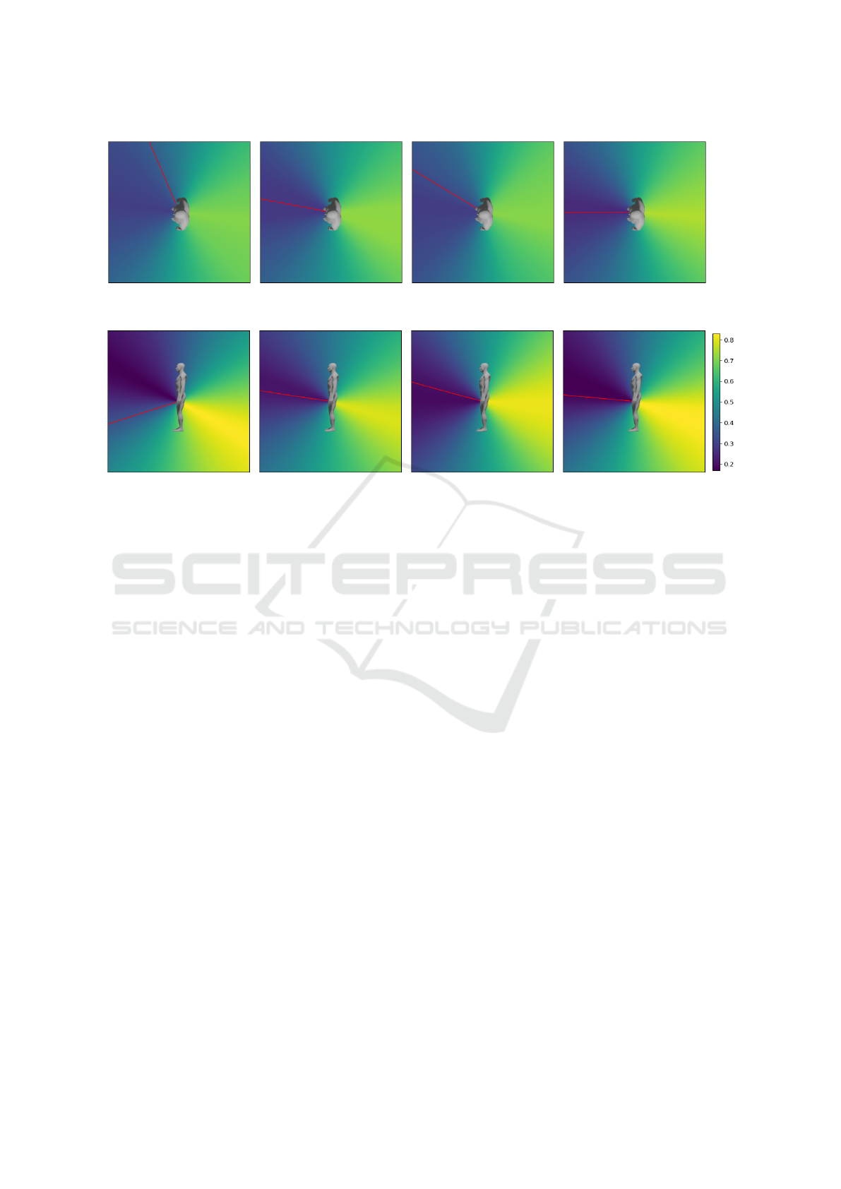
(a) Bench Press (b) Squat (c) Bend Down (d) Stand
(e) Bench Press (f) Squat (g) Bend Down (h) Stand
Figure 8: View Selection Error (VSE) for different viewing angles from the top (a-d) and side (e-h) using the method of
Dutagaci et al. (Dutagaci et al., 2010) without symmetry. The left represents the front. The red line represents the view
direction selected by our method. The human silhouette is for spatial orientation only and does not represent the executed
movements.
the selection of the users best with a mean view se-
lection error of 0.3467. The isometric-like view per-
formed second best with 0.347 followed by JMO with
0.4825 and the method of Kwon et al. with 0.5497.
7.2 Method Analysis
To understand the comparison of methods in subsec-
tion 7.3, it is crucial to comprehend what viewpoints
the compared methods provide and how their succes-
sion appears over time.
JMO (Ishara et al., 2015). The JMO algorithm em-
ployed predominantly a good overview of the human
body. The biggest deficit was that the algorithm er-
ratically changed viewpoints to positions far away
from each other. This can be perceived in Figure 9.
Consequently, the feedback was difficult to perceive,
as the algorithm was not designed to display visual
cues. Additionally, several viewpoints were selected
from below, although participants preferred perspec-
tives from slightly above (see subsection 7.1).
Kwon et al. (Kwon et al., 2020). As Figure 10 shows,
the algorithm of Kwon et al. seemed to prefer views
from behind in our examples. As elaborated in sub-
section 7.1 this is an unusual view for humans and
mostly avoided by users. In addition, views from be-
low were occasionally selected like in the algorithm
above. The algorithm of Kwon et al. provided a far
more stable view than JMO. Although, the feedback
was often difficult to see.
Ours. Our algorithm provided a consistent transi-
tion between an optimal viewpoint for the neutral
position to the contracted position with deviation as
seen in Figure 11. If feedback occurred it was dis-
played well and there was a perceivable emphasis on
it. However, in some exercises the repetition execu-
tion was fast and the neutral and feedback-optimized
viewpoints seemed conflicting. The result was a fast
camera movement, which irritated some users.
7.3 Viewpoint Comparison
Table 1 shows the distribution of user choices in the
viewpoint comparison. Our algorithm was chosen
most frequently with 35.04 % of votes, the neutral po-
sition was chosen second most with 32.48 % followed
by Kwon et al. (Kwon et al., 2020) with 17.52 % and
lastly JMO (Ishara et al., 2015) with 14.96 %.
The methods of Kwon et al. (Kwon et al., 2020)
and Ishara et al. (Ishara et al., 2015) both occasionally
provided camera positions from behind. Additionally,
they produced a camera movement, which was un-
steady because it jumped to perspectives and a lim-
ited number of viewpoints. In contrast, the static neu-
HUCAPP 2024 - 8th International Conference on Human Computer Interaction Theory and Applications
358
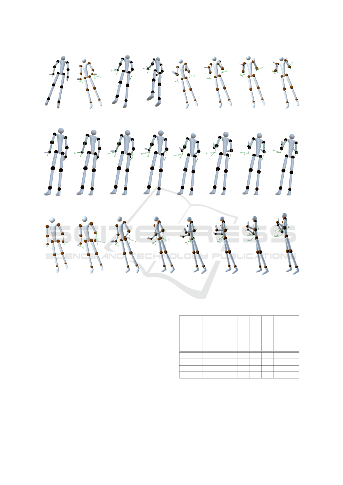
Figure 9: Image sequence, taken from a video of a biceps curl exercise with deviation. The viewpoint is optimized by the
Joint Mutual Occlusion algorithm by Ishara et al. (Ishara et al., 2015).
Figure 10: Image sequence, taken from a video of a biceps curl exercise with deviation. The viewpoint is optimized by the
algorithm by Kwon et al. (Kwon et al., 2020).
Figure 11: Image sequence, taken from a video of a biceps curl exercise with deviation. The viewpoint is optimized by our
algorithm.
tral viewpoint from the oblique front delivered sur-
prisingly good results, although it lacked an adaption
for movement or feedback. The biggest advantage of
the neutral viewpoint compared to the other methods
was the steadiness. Our method provided a good view
of the neutral positions of the exercises. Furthermore,
it produces a continuous camera movement toward a
feedback-oriented viewpoint at the highest deviation.
However, the camera movement showing the bench
press and bend-over row exercises was in parts fast.
7.4 Computation Time
Our algorithm performed the fastest compared to the
other algorithms. JMO took an average of 200.83 ms
for one frame to calculate. The algorithm presented in
the work of Kwon et al. took 16.84 ms and ours 0.18
ms on average. The calculations were executed on
Table 1: Results of user study. Distribution of how often
different viewpoint selection methods have been chosen by
the participants.
Method
Bench press
Biceps curl A
Lateral raises
Shoulder press
Bend over row
Biceps curl B
Total
Percentage
Neutral 19 15 3 15 6 18 32.48 %
JMO 1 1 6 0 25 2 14.96 %
Kwon 14 7 3 3 6 8 17.52 %
ours 5 16 27 21 2 11 35.04 %
an Intel(R) Core(TM) i7-8750H CPU with 2.21 GHz.
The visualization and feedback generation needed ad-
ditional ressources, which meant only our algorithm
was able to run in real time for our application.
Automatic Viewpoint Selection for Interactive Motor Feedback Using Principle Component Analysis
359

8 INSIGHTS / DISCUSSION
Looking at Figure 8 it becomes evident that a frontal
view was highly preferred by the participants. This is
consistent with the statement made by Zusne (Zusne,
1970), that frontal views are desired by humans, as
mentioned in section 3 and confirms these require-
ments for our use case. Furthermore, it can be ob-
served that our participants preferred a view from
slightly above.
In some of the exercises, our algorithm performs
significantly less well. This can be attributed to the
constantly smooth but occasionally fast camera move-
ment. In particular, the bench press and bend-over
row had fast-moving results regarding camera move-
ment. As stated in section 4 our algorithm does not al-
low for inconsistent camera movement, yet fast cam-
era motions can occasionally occur.
The most common statement made by the par-
ticipants regarded the consistency of camera move-
ment. Specifically, movements that were too fast or
shaky were highly irritating to the users. This ob-
servation matches the research by Assa et al. (Assa
et al., 2008) analyzing camera paths. Furthermore,
it was often stated that multiple camera perspectives
would be beneficial for understanding the poses and
feedback. This is especially interesting for future
work and when applying suggested methods. In ad-
dition, some users wished for the option to choose no
method, as they found none of the suggested perspec-
tives fit. This implies that there are improvements to
our algorithm, that need further assessment. Lastly,
it was hard for some users to interpret poses without
relation to the surroundings. This applied primarily to
the bench press exercise, where a virtual bench repre-
sentation might be helpful to interpret the lying pos-
ture of the avatar. Hence, it could be beneficial for the
understanding to include surroundings when work-
ing with exercises including equipment like weights,
benches, pull-up bars, etc. However, it must be re-
membered that additional rendered equipment could
occlude the avatar or visual cues and make it more
difficult to perceive the provided feedback.
9 CONCLUSION
The extent of interactive support, that technology can
provide when learning new skills, is steadily grow-
ing. Consequently, it becomes increasingly important
to find fast and practical ways to implement func-
tionalities at the foundation of human-computer in-
teraction like viewpoint selection. We presented a
novel method to consider real-time motion feedback
in viewpoint selection at a computationally low cost.
Furthermore, we describe a user study that showed
that our algorithm was not only the fastest but also
the one preferred by the users to display feedback.
Considering the Nested Model for Visualization De-
sign and Validation of Munzner (Munzner, 2009), we
outperformed the methods found in the current litera-
ture on the data/operation abstraction layer as well as
the algorithm layer.
While we achieved satisfying results compared to
methods found in the literature, there is still an op-
portunity for improvement. In particular, it became
apparent that users disliked fast or inconsistent cam-
era movements. This calls for an optimization that
limits movement speed, while still optimally display-
ing feedback in real-time. As these appear to be con-
flicting goals, research into a solution representing a
feasible compromise is needed.
The impact of a hierarchical drill-down mecha-
nism for joints should be further researched. It might
be interesting to link certain camera control aspects
to the hierarchical dependency of joints, for example,
zoom. This could potentially create a dynamic cam-
era control, which makes it possible to display pre-
cisely the crucial corrections. However, to ensure this,
it has to be further analyzed in which order humans
correct their deviations optimally, what factors play
into this, and how technology can support it.
When implementing motion feedback it could also
help users understand the feedback to include several
viewpoints and render props to help set the avatar in
relation to its surroundings.
ACKNOWLEDGEMENTS
The mixed reality part of this work was sup-
ported by ProFIL - Programm zur F
¨
orderung des
Forschungspersonals, Infrastruktur und forschendem
Lernen of HS Worms. All other work was supported
by ZIM grant 16KN087122 from the German Federal
Ministry for Economic Affairs and Energy. The au-
thors wish to thank stimmel-sports e.V and the Skill-
box project for inspiration. The authors also would
like to thank the reviewers for their many construc-
tive remarks and suggestions which greatly helped to
improve the paper.
REFERENCES
Ant
´
on, D., Go
˜
ni, A., and Illarramendi, A. (2015). Exer-
cise Recognition for Kinect-based Telerehabilitation*.
Methods of Information in Medicine, 54(02):145–155.
HUCAPP 2024 - 8th International Conference on Human Computer Interaction Theory and Applications
360

Assa, J., Caspi, Y., and Cohen-Or, D. (2005). Action synop-
sis: pose selection and illustration. ACM Transactions
on Graphics (TOG), 24(3):667–676.
Assa, J., Cohen-Or, D., Yeh, I.-C., and Lee, T.-Y. (2008).
Motion overview of human actions. ACM Transac-
tions on Graphics, 27(5):1–10.
Borisenko, A. I. and Tarapov, I. E. (1979). Vector and Ten-
sor Analysis with Applications, page 109. Dover Pub-
lications Inc., New York.
Bouwmans, T., Javed, S., Zhang, H., Lin, Z., and Otazo,
R. (2018). On the applications of robust pca in im-
age and video processing. Proceedings of the IEEE,
106(8):1427–1457.
Charalambides, C. (2002). Enumerative Combinatorics,
page 62. Discrete Mathematics and Its Applications.
Taylor & Francis.
Choi, M. G., Yang, K., Igarashi, T., Mitani, J., and Lee, J.
(2012). Retrieval and Visualization of Human Motion
Data via Stick Figures. Computer Graphics Forum,
31(7):2057–2065. Valuable Database.
Diller, F., Scheuermann, G., and Wiebel, A. (2022). Visual
cue based corrective feedback for motor skill training
in mixed reality: A survey. IEEE Transactions on Vi-
sualization and Computer Graphics, pages 1–14.
Dutagaci, H., Cheung, C. P., and Godil, A. (2010). A bench-
mark for best view selection of 3D objects. Proceed-
ings of the ACM workshop on 3D object retrieval -
3DOR ’10, pages 45–50.
Ishara, K., Lee, I., and Brinkworth, R. (2015). Mobile
Robotic Active View Planning for Physiotherapy and
Physical Exercise Guidance. 2015 IEEE 7th Interna-
tional Conference on Cybernetics and Intelligent Sys-
tems (CIS) and IEEE Conference on Robotics, Au-
tomation and Mechatronics (RAM), pages 130–136.
Kiciroglu, S., Rhodin, H., Sinha, S. N., Salzmann, M., and
Fua, P. (2020). ActiveMoCap: Optimized Viewpoint
Selection for Active Human Motion Capture. Pro-
ceedings of the IEEE/CVF Conference on Computer
Vision and Pattern Recognition 2020.
Kwon, B., Huh, J., Lee, K., and Lee, S. (2020). Optimal
Camera Point Selection Toward the Most Preferable
View of 3-D Human Pose. IEEE Transactions on Sys-
tems, Man, and Cybernetics: Systems, 52(1):533–553.
Kwon, J.-Y. and Lee, I.-K. (2008). Determination of camera
parameters for character motions using motion area.
The Visual Computer, 24(7-9):475–483.
Microsoft Development Team (2018). Azure Kinect DK
documentation. https://learn.microsoft.com/en-us/
azure/kinect-dk/, Accessed: 2023-3-30.
Munzner, T. (2009). A Nested Model for Visualization De-
sign and Validation. IEEE TVCG, 15(6):921–928.
Nundy, S., Lotto, B., Coppola, D., Shimpi, A., and Purves,
D. (2000). Why are angles misperceived? Proceed-
ings of the National Academy of Sciences of the United
States of America.
Nu
˜
nez, J. R., Anderton, C. R., and Renslow, R. S. (2018).
Optimizing colormaps with consideration for color vi-
sion deficiency to enable accurate interpretation of sci-
entific data. PLOS ONE, 13(7):1–14.
Polonsky, O., Patan´e, G., Biasotti, S., Gotsman, C., and
Spagnuolo, M. (2005). What’s in an Image ? The
Visual Computer.
Rudoy, D. and Zelnik-Manor, L. (2011). Viewpoint Se-
lection for Human Actions. International Journal of
Computer Vision, 97(3):243–254.
Saenz-de Urturi, Z. and Soto, B. G.-Z. (2016). Kinect-
Based Virtual Game for the Elderly that Detects Incor-
rect Body Postures in Real Time. Sensors, 16(5):704.
Shi, Z., Yu, L., El-Latif, A. A. A., Le, D., and Niu, X.
(2012). A Kinematics Significance Based Skeleton
Map for Rapid Viewpoint Selection. International
Journal of Digital Content Technology and its Appli-
cations, 6(1):31–40.
Skaro, J., Hazelwood, S. J., and Klisch, S. M. (2021).
Knee Angles After Crosstalk Correction With Princi-
pal Component Analysis in Gait and Cycling. Journal
of Biomechanical Engineering, 143(5):054501.
Sorzano, C., Vargas, J., and Pascual-Montano, A. (2014).
A survey of dimensionality reduction techniques.
ArXiv14032877 Cs Q-Bio Stat.
Su, C.-J. (2013). Personal Rehabilitation Exercise Assis-
tant with Kinect and Dynamic Time Warping. Inter-
national Journal of Information and Education Tech-
nology, pages 448–454.
Wang, M., Guo, S., Liao, M., He, D., Chang, J., and Zhang,
J. (2019). Action snapshot with single pose and view-
point. The Visual Computer, 35(4):507–520.
Yeh, I., Lin, C., Chien, H., and Lee, T. (2011). Efficient
camera path planning algorithm for human motion
overview. Computer Animation and Virtual Worlds,
22(2-3):239–250.
Zusne, L. (1970). Visual Perception of Form. Academic
Press.
Automatic Viewpoint Selection for Interactive Motor Feedback Using Principle Component Analysis
361
