
Multi-View 3D Reconstruction for Construction Site Monitoring
Guangan Chen
a
, Michiel Vlaminck
b
, Wilfried Philips and Hiep Luong
c
Image Processing and Interpretation (IPI), imec Research Group at Ghent University,
Department of Telecommunications and Information Processing (TELIN), Ghent University, Belgium
Keywords:
Construction Progress Monitoring, Structure-from-Motion, Multi-View Stereo, Point Cloud Registration.
Abstract:
Monitoring construction sites is pivotal in effective construction management. Building Information Modeling
(BIM) is vital for creating detailed building models and comparing actual construction with planned designs.
For this comparison, a 3D model of the building is often generated using images captured by handheld cameras
or Unmanned Aerial Vehicles. However, this approach does not provide real-time spatial monitoring of on-
site activities within the BIM model. To address this challenge, our study utilizes fixed cameras placed at
predetermined locations within an actual construction site. We captured images from these fixed viewpoints
and used classical multi-view stereo techniques to create a 3D point cloud representing the as-built building.
This point cloud is then aligned with the as-planned BIM model through point cloud registration. In addition,
we proposed an algorithm to convert SfM reprojection error into a value with metric units, resulting in a mean
SfM reprojection error of 4.17cm. We also created voxel volumes to track and visualize construction activities
within BIM coordinate system, enhancing real-time site monitoring and improving construction management.
1 INTRODUCTION
Construction site monitoring is a cornerstone in the
architecture, engineering, and construction industry,
acting as a vital mechanism to ensure that the pro-
gression of projects is in alignment with predeter-
mined schedules and designs. Accurate progress re-
porting can enable stakeholders to make effective de-
cisions according to the as-built states and may pre-
vent the project from cost overruns and construction
delays (Sami Ur Rehman et al., 2022; Kim et al.,
2009; Oh et al., 2004).
Traditional construction progress monitoring
(CPM) methods rely on manual and labor-intensive
processes for gathering information, documenting,
and periodically reporting the status of a construction
project, which are tedious, slow, and susceptible to
errors, often yielding redundant information (Sami
Ur Rehman et al., 2022).
Computer Vision (CV), an advanced technology
that processes visual inputs like photos or videos has
emerged as a leading advanced solution in the field of
automated CPM. The typical procedure of CV-based
CPM includes data acquisition, information retrieval,
a
https://orcid.org/0000-0002-2238-483X
b
https://orcid.org/0000-0003-3986-823X
c
https://orcid.org/0000-0002-6246-5538
progress estimation, and output visualization (Sami
Ur Rehman et al., 2022).
Data acquisition involves applying image sen-
sors from various devices like handheld and fixed
on mounts cameras, or Unmanned Aerial Vehicles
(UAVs), to collect visual as-built data. UAVs are
highly effective in covering large, remote areas but
face flight restrictions (Kim et al., 2019; Sami
Ur Rehman et al., 2022). Handheld cameras are
portable and detail-oriented but are user-dependent
and prone to errors (Sami Ur Rehman et al., 2022;
Golparvar-Fard et al., 2009). Fixed cameras, on
the other hand, positioned at consistent elevations,
offer automated and reliable data collection in var-
ied weather, which is ideal for real-time and long-
term construction monitoring (Sami Ur Rehman et al.,
2022).
The information retrieval process aims to extract
valuable insights from visual data, typically form-
ing an as-built 3D model for comparison with the
as-planned model to assess progress. Multi-view
stereo (Furukawa et al., 2015) serves as a cost-
effective technique to transform 2D images into 3D
models, although with less precision compared to Li-
dar (Sepasgozar et al., 2014), and demands consider-
able processing time for larger vision datasets (Sami
Ur Rehman et al., 2022).
Chen, G., Vlaminck, M., Philips, W. and Luong, H.
Multi-View 3D Reconstruction for Construction Site Monitoring.
DOI: 10.5220/0012308300003660
Paper published under CC license (CC BY-NC-ND 4.0)
In Proceedings of the 19th International Joint Conference on Computer Vision, Imaging and Computer Graphics Theory and Applications (VISIGRAPP 2024) - Volume 4: VISAPP, pages
469-476
ISBN: 978-989-758-679-8; ISSN: 2184-4321
Proceedings Copyright © 2024 by SCITEPRESS – Science and Technology Publications, Lda.
469

Progress estimation in CV-based CPM aims to
compare the as-built point cloud to as-planned Build-
ing Information Models (BIMs) (Azhar, 2011; Sami
Ur Rehman et al., 2022). This comparison can be
conducted by BIM registration, i.e., point cloud reg-
istration, which includes coarse registration and fine
registration (Besl and McKay, 1992).
Output visualization displays insights from infor-
mation retrieval or progress estimation. Activities
are typically annotated on 2D images using bound-
ing boxes (Karsch et al., 2014). Advanced methods
leverage Augmented Reality (AR) and Virtual Reality
(VR) to merge the BIM model with the as-built scene
for an immersive construction progress view (Ahmed,
2019).
Despite the potential of CV-based CPM to im-
prove construction monitoring by automating pro-
cesses and reducing reliance on labor-intensive meth-
ods, the generation of an as-built 3D point cloud re-
quires the collection of a large dataset from construc-
tion sites, which is a labor-intensive task (Xue et al.,
2021; Sami Ur Rehman et al., 2022).
As the use of surveillance cameras for monitor-
ing construction sites continues to spread, the utiliza-
tion of the vast amount of images and videos cap-
tured daily for as-built information extraction gains
more attention. In our study, we utilized images
obtained from surveillance cameras to generate as-
built point clouds, followed by a comparison with the
BIM model. Using the homography derived from this
comparison, we tracked on-site activities by forming
voxel volumes of workers and integrated these vol-
umes into the BIM model for visualization.
Our main contributions can be summarized as fol-
lows:
i. We collected a dataset consisting of images from
eight different viewpoints of a real-world con-
struction site, capturing images both day and night
throughout the construction period.
ii. We propose an integrated pipeline to generate 3D
point clouds from construction sites using im-
agery from fixed cameras and to match them with
existing BIM models.
iii. We validated our pipeline by performing an ex-
periment on a fixed-camera dataset of a real con-
struction site for which a BIM model is available.
2 RELATED WORK
2.1 CV-Based CPM
Comparing an as-built building to a BIM model for
monitoring construction progress has been studied
for years (Tuttas et al., 2017; Mahami et al., 2019;
Khalid Masood et al., 2020). Tuttas et al. (Tuttas
et al., 2017) proposed a procedure for continuous con-
struction progress monitoring. The procedure begins
with the placement of markers on the initial construc-
tion site. These markers serve as feature points in the
structure-from-motion (Furukawa et al., 2015) pro-
cess. This setup allows the collected images on the
required dates to be accurately registered in the SfM
step, resulting in the generation of an accurate as-
built point cloud, which is then compared to a BIM
model. Likewise, Mahami et al.(Mahami et al., 2019)
employed coded targets affixed to walls as distinctive
features to enhance the precision of estimated cam-
era poses. The authors used handheld cameras to
collect images of a building, followed by creating an
as-built point cloud of the building using multi-view
stereo (Furukawa et al., 2015) and comparing the
generated point cloud with BIM model. Masood et
al. (Khalid Masood et al., 2020) deployed two crane
camera developed by Pix4D
1
to capture images of
the entire construction process, and the as-built point
cloud was generated by the Pix4D system. The au-
thors aligned the point cloud with the BIM model us-
ing the georeferencing of the point cloud.
2.2 Image-Based 3D Reconstruction
Image-based 3D reconstruction has been an active
research area for several decades, intending to re-
construct 3D structures from multiple 2D images
captured from different viewpoints (Furukawa et al.,
2015; Hartley and Zisserman, 2003). A typical
pipeline for 3D Reconstruction includes structure-
from-motion (SfM) and multi-view stereo (MVS),
where SfM yields the camera poses and a sparse point
cloud and MVS creates dense point clouds using the
estimated camera poses obtained by SfM (Furukawa
et al., 2015; Hartley and Zisserman, 2003).
In addition, frameworks for SfM and MVS
are proposed, such as COLMAP (Sch
¨
onberger and
Frahm, 2016), OpenSfM
2
, and OpenMVS
3
. How-
ever, creating a 3D point cloud for an ultra-large-
scale scene with sparse viewpoints remains challeng-
ing (Zhang et al., 2021).
1
https://www.pix4d.com/
2
https://github.com/mapillary/OpenSfM
3
https://github.com/cdcseacave/openMVS
VISAPP 2024 - 19th International Conference on Computer Vision Theory and Applications
470
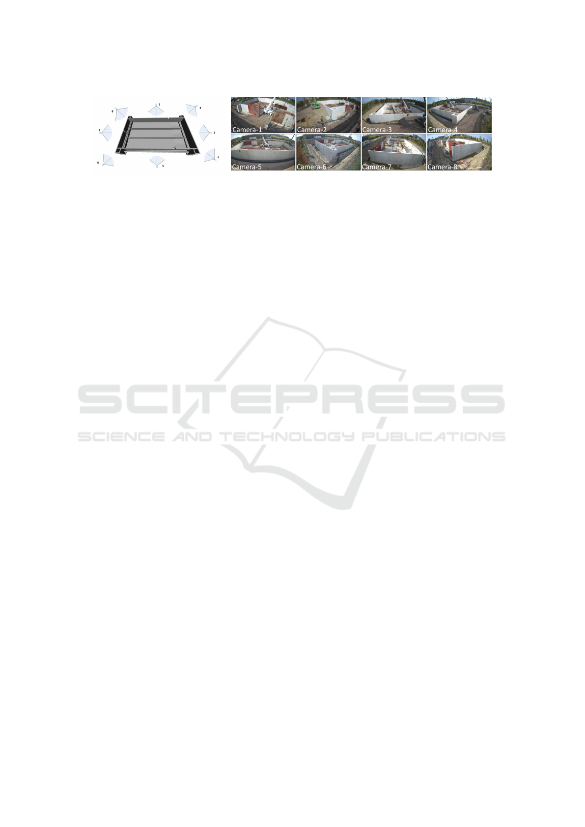
(a) Placement of cameras. (b) Corresponding images of viewpoints.
Figure 1: The eight predetermined camera viewpoints at the construction site. Cameras are positioned to continuously monitor
the site, capturing images day and night at varying frequencies—every 5 minutes during active construction hours.
3 DATASET
We deployed eight high-resolution (4K) and wide-
angle view cameras at fixed positions across the con-
struction site to collect a dataset. The corresponding
viewpoints are illustrated in Figure 1. The cameras
were mounted on cranes or poles, and their locations
were chosen based on a comprehensive analysis of the
site’s layout, ensuring that each camera provided a
unique viewpoint, thereby maximizing the coverage
and minimizing the redundancy in the captured im-
ages.
To capture varying stages and activities of con-
struction throughout the construction’s entirety, the
cameras were programmed to automatically capture
images at different intervals. Between 6 a.m. and 7
p.m., images were taken every 5 minutes to closely
monitor the most active period of construction activ-
ities. Conversely, during the less active hours, span-
ning from 7 p.m. to 6 a.m., the cameras captured im-
ages at 30-minute intervals.
4 METHOD
A pipeline is proposed for comparing the as-built
building with the as-planned BIM model using the
collected images, as illustrated in Figure 2. We first
generate a point cloud representative of the as-built
structure using the classical image-based 3D recon-
struction pipeline that includes structure-from-motion
(Section 4.1) and multi-view stereo (Section 4.2).
Upon the successful generation of the point cloud,
a point cloud registration approach is subsequently
employed to align the derived point cloud with the
as-planned BIM model (Section 4.3).
4.1 Structure-from-Motion
The structure-from-motion (SfM) algorithm serves as
a foundational mechanism to convert input images
into outputs of camera parameters and a set of 3D
points, referred to as a sparse model. Incremental
SfM, recognized for its widespread application, im-
plements this through a pipeline (Furukawa et al.,
2015; Sch
¨
onberger and Frahm, 2016), involving 1)
feature detection and matching enhanced with geo-
metric verification, 2) initialization of the foundation
for the reconstruction stage via careful selection of
two-view reconstruction, and 3) the registration of
new images through triangulation of scene points,
outlier filtration, and refinement of the reconstruction
using bundle adjustment (BA).
4.1.1 Feature Extraction and Feature Matching
In the feature detection and matching stage of the
SfM pipeline, the objective is to identify distinctive
points in the images and establish accurate correspon-
dences between them. Accurate feature extraction
and matching play a pivotal role in achieving success-
ful 3D reconstruction and camera pose estimation.
Traditional methods such as SIFT (Lowe, 2004)
and SURF (Bay et al., 2006), based on handcrafted
features, face challenges with viewpoint changes and
repetitive patterns. Recent advancements in deep
learning-based methods (LeCun et al., 2015; Ma
et al., 2021) have shown superior performance in
image matching. In our study, we utilize Super-
Point (DeTone et al., 2018) for efficient interest
point detection and description, and SuperGlue (Sar-
lin et al., 2020) for robust feature matching.
4.1.2 Initialization
The initial selection of an appropriate image pair is
crucial in the SfM process. Inadequate initialization
can lead to reconstruction failures, and the subsequent
robustness, accuracy, and performance of the incre-
mental reconstruction heavily depend on this initial
step. To have a more robust and accurate reconstruc-
tion, the initial image I
0
is selected in the image graph
with the most overlapping cameras. A sequence of
Multi-View 3D Reconstruction for Construction Site Monitoring
471
Detector
Detector
Descriptor
Descriptor
Matching
and
Filtering
Geometrical
verification:
RANSAC
8-point algorithm Triangulation
SuperPoint SuperGlue
camera poses
sparse point cloud
Depth maps
estimation
Depth maps
fusion
dense point cloud
Coarse
registration
Fine
registration
(1) Structure-from-Motion
(2)Multi-view stereo
(3)Point cloud registration
1
2
3
4
4
3
2
1
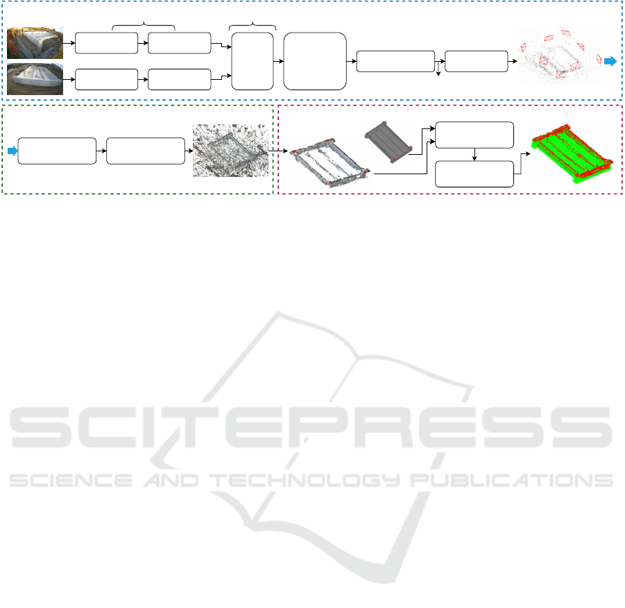
Figure 2: Proposed pipeline for comparing the as-built building with the as-planned BIM model. The pipeline includes,
1) estimating camera poses using structure-from-motion, 2) generating a dense point cloud using multi-view stereo, and 3)
aligning the created point cloud with BIM model using point cloud registration. Note that noise points are manually removed
from the dense point cloud before performing point cloud registration, and the BIM model is converted into a point cloud
from a mesh.
images is then determined by prioritizing pairs with
the highest match count, starting with (I
0
, I
1
). Itera-
tively, for a given image I
k
in the sequence, the next
image I
k+1
is selected based on its maximum match
count with I
k
from the set of unsequenced images.
Image I
k+1
is then appended to the sequence and re-
moved from the set of unsequenced images. This pro-
cedure continues until all images are sequenced or no
matches can be found for the most recent image in the
sequence.
With the initial image pair (I
0
, I
1
), the eight-point
algorithm is used to calculate the initial model (Hart-
ley and Zisserman, 2003).
In the use case of two camera views, the epipolar
constraint between the cameras is given by:
p
2
T
K
−T
EK
−1
p
1
= 0. (1)
Here, p
1
and p
2
represent the corresponding 2D
points in the first and second camera views for a 3d
point P, which are the matches keypoints obtained in
the step of feature extraction and matching. K is the
intrinsic parameters of the cameras. E is the essential
matrix represented as E = [t]
×
R, where t and R cor-
respond to the translation vector and rotation matrix,
respectively, with [t]
×
being the skew-symmetric ma-
trix associated with t (Hartley and Zisserman, 2003).
To estimate the translation vector t and rotation matrix
R, the eight-point algorithm (Hartley, 1997; Longuet-
Higgins, 1981) is used to calculate E, followed by de-
riving the t and R using singular value decomposition
(SVD) (Hartley and Zisserman, 2003). Since there are
typically more than eight pairs of keypoints, and some
matches may be incorrect, we utilize RANSAC (Fis-
chler and Bolles, 1981) to filter out unreliable matches
before estimating E.
4.1.3 Triangulation
After obtaining camera poses for two viewpoints, we
calculate the corresponding 3D points of matches be-
tween the two images using the Direct Linear Trans-
form (DLT) method. This method leverages the pro-
jection matrices of the cameras and the corresponding
points in the images (Hartley and Zisserman, 2003).
4.1.4 Register Next Images
Starting with the initial 3D model, each subsequent
image from the image sequence, created during the
initialization phase, is systematically aligned to the
model. This registration is achieved by solving the
Perspective-n-Point (PnP) problem (Furukawa et al.,
2015) that estimates the camera pose from a set of
2D image feature correspondences and their corre-
sponding 3D points. In our study, we adopted the
RANSAC-based PnP method (Furukawa et al., 2015;
Hartley and Zisserman, 2003). Subsequently, the esti-
mated camera pose is used to calculate the 3D points
of matches of the subsequent image, followed by
adding the 3D points to the 3D model. To enhance
the accuracy of the alignment, bundle adjustment is
employed. This iterative alignment process continues
until all images in the sequence have been registered.
4.1.5 Bundle Adjustment
Bundle adjustment (BA) aims to refine camera poses,
intrinsic parameters, and 3D scene structure by iter-
atively minimizing the reprojection error. In incre-
mental SfM, BA is processed after registering each
image (Hartley and Zisserman, 2003).
Reprojection error quantifies the disparity be-
tween the observed 2D image points u
i
and their cor-
VISAPP 2024 - 19th International Conference on Computer Vision Theory and Applications
472

responding projected 3D points X
i
in the camera co-
ordinate system. Given a set of N 2D image points u
i
and their corresponding 3D points X
i
, and consider-
ing the camera projection matrix P, the reprojection
error E is defined as:
E =
N
∑
i=1
∥u
i
− PX
i
∥
2
. (2)
The goal of BA is to solve for the optimal camera
parameters P and 3D scene points X that minimize the
reprojection error across all observed image points.
This iterative optimization process ensures that the re-
constructed 3D scene aligns more accurately with the
observed 2D image data, resulting in improved recon-
struction fidelity.
4.2 Multi-View Stereo
Multi-view stereo (MVS) aims to create a dense point
cloud of a scene using multiple images with known
camera poses. Depth map estimation and fusion are
the main steps in classical MVS (Furukawa et al.,
2015). In our study, we obtain image correspondences
and camera parameters during the SfM step, followed
by image rectification. Since our goal is to generate a
dense point cloud, we primarily focus on depth map
estimation and fusion in this section.
Depth map estimation aims to assign a depth
value to each pixel in an image, representing the dis-
tance from the camera to the corresponding point in
the scene (Hartley and Zisserman, 2003; Pollefeys
et al., 2008). The challenge in this step is to ascer-
tain the depth that maximizes both photo-consistency
and geometry-consistency across multiple images for
each pixel. Photo-consistency ensures that the appear-
ance of a point is consistent across different views,
while geometry-consistency ensures that the recon-
structed 3D point is geometrically plausible and con-
sistent with neighboring points in terms of depth and
surface normals. For robust and accurate depth map
estimation, we adopt the PatchMatch stereo (Bleyer
et al., 2011; Barnes et al., 2009) algorithm, which op-
timizes correspondences between patches (small re-
gions in stereo images) instead of individual pixels.
Depth map fusion aims to create a 3D point cloud
of a scene by integrating depth maps. The typical pro-
cedure begins by refining depth values using probabil-
ity masks, followed by visibility filtering across mul-
tiple viewpoints to improve accuracy. Afterward, the
refined depth maps are back-projected into 3D space
to generate point clouds. These constructed point
clouds are then combined, resulting in a detailed and
accurate 3D representation of the scene (Furukawa
et al., 2015).
4.3 Alignment of Point Cloud and BIM
Model
The generated point cloud is aligned to the BIM
model using a point cloud registration method. Point
cloud registration aims to find the transformation (ro-
tation, translation, and possibly scaling) that mini-
mizes the distance between corresponding points in
two point clouds, which typically unfolds in two main
stages: coarse registration and fine registration (Besl
and McKay, 1992).
Coarse registration, the initial phase in point cloud
alignment, seeks an approximate transformation be-
tween point clouds, typically using methods like fea-
ture matching or geometric primitives (Rusinkiewicz
and Levoy, 2001; Chetverikov et al., 2002). Due to
incomplete point clouds from ongoing construction
in our study, we manually select corresponding points
and compute the transformation matrix using Singular
Value Decomposition (SVD) of the cross-covariance
matrix between the point sets (Arun et al., 1987; Besl
and McKay, 1992; Eggert et al., 1997).
Consider points A = (a
1
, a
2
, . . . , a
n
) and B =
(b
1
, b
2
, . . . , b
n
) to be the corresponding manually
picked points for the BIM model and the generated
point cloud, respectively. To align the generated point
cloud to the BIM model, we align the points B to A.
We first compute the centroids c
A
and c
B
as follows:
c
A
=
1
N
N
∑
i=1
a
i
, (3)
c
B
=
1
N
N
∑
i=1
b
i
. (4)
Next, we translate both points such that their cen-
troids are at the origin, resulting in the centered points
¯
A and
¯
B:
¯
A = A − 1
⊤
c
A
, (5)
¯
B = B − 1
⊤
c
B
, (6)
where 1 = (1
1
, . . . , 1
N
).
The cross-covariance matrix H between the cen-
tered point sets is computed as:
H =
N
∑
i=1
¯
B
i
⊗
¯
A
i
, (7)
where ⊗ denotes the outer product of two vectors. Us-
ing SVD on H, we decompose it as:
H = UΣ
Σ
ΣV
T
, (8)
from which the rotation matrix R is derived as:
R = V
T
U
T
. (9)
Multi-View 3D Reconstruction for Construction Site Monitoring
473

The scaling factor s is then computed based on the
ratio of the norms of the centered points:
s =
∑
N
i=1
||
¯
A
i
||
2
∑
N
i=1
||R
¯
B
i
||
2
. (10)
With the rotation matrix A and scaling factor s, the
translation vector t is computed as:
t = C
A
− sRC
B
. (11)
Finally, the transformation matrix T
c
is con-
structed in homogeneous coordinates as:
T
c
=
sR t
0 1
. (12)
After coarse registration, fine registration refines
the alignment to achieve high-precision alignment be-
tween the aligned point cloud and the BIM model.
The Iterative Closest Point (ICP) algorithm is a
widely-used method for fine registration (Besl and
McKay, 1992). In our case, we employ the point-
to-point ICP algorithm that iteratively minimizes the
distance between corresponding points until prede-
fined convergence criteria are met, typically based on
a maximum number of iterations.
5 REPROJECTION ERROR OF
SfM IN METRIC UNITS
The purpose of analyzing the reprojection error in
metric units is to quantify the error using the metric
units of the BIM model so that it can become mean-
ingful for construction sector specialists.
To achieve this, we initially use the point cloud as
a reference and align the BIM model with the point
cloud using a coarse point cloud registration method,
as discussed in Section 4.3. This alignment yields two
point sets: A (a
1
, a
2
, . . . , a
i
) for the point cloud and B
(b
1
, b
2
, . . . , b
i
) for the aligned BIM model.
For a single viewpoint, we back-project the point
sets A and B onto the 2D image plane, yielding point
sets A
′
= (a
′
1
, a
′
2
, . . . , a
′
i
) and B
′
= (b
′
1
, b
′
2
, . . . , b
′
i
),
respectively. The reprojection error of SfM, expressed
in metric units and corresponding to a single point in
the BIM model, is calculated as:
E
S f M
=
D(a
i
, b
i
) λ
D(a
′
i
, b
′
i
)
E
re
, (13)
where D(·) denotes the Euclidean distance, λ is the
unit distance in metric units derived from the BIM
model coordinate system, and E
re
is the reprojection
error of SfM in pixel.
6 RESULT
A 3D point cloud of the construction site was success-
fully generated using images from only eight distinct
viewpoints. The 3D point cloud of the construction
site is generated using images captured at different
times, accounting for the varying illumination condi-
tions throughout the day.
Figure 3a presents a dense point cloud generated
using images from the eight viewpoints taken during
daylight, with each viewpoint represented by a single
image. A section of a wall failed to be reconstructed
due to the absence of matches in the reflective area, as
highlighted in Figure 3d. In contrast, Figure 3b dis-
plays a point cloud generated from nighttime images,
where a wall section, annotated by a green dotted line,
remains unreconstructed. Given that the construction
site is treated as a static scene, image features are in-
fluenced by the texture of the building, which fluctu-
ates with changing outdoor illumination. By merging
images taken at different times, the texture diversity
is enhanced, leading to increased image features and
matches. This approach facilitates a more complete
point cloud representation of the building. For exam-
ple, the point cloud in Figure 3c was reconstructed
using images that were used to create the two previ-
ously mentioned point clouds, including four walls.
We applied this method to create a dense model for
the complete building, resulting in a SfM reprojection
error (E
re
) of 0.72 pixels.
In the coarse registration step, the four corners
of the building were selected as correspondences, as
shown in Figure 2. Using the homography derived
from the alignment, we computed the reprojection er-
ror of SfM in metric units. The mean of SfM repro-
jection error in metric units across all viewpoints is
4.17cm, and the ranges of each viewpoint are pre-
sented in Table 1. The table clearly shows that repro-
jection errors differ among viewpoints, with a larger
spread in maximum errors (7.86 cm) compared to
minimum errors (1.96 cm). The error could be caused
by imprecise camera pose estimations. Moreover, the
generated dense point is incomplete and has holes
because of sparse views, which may cause inaccu-
racies in manually selected points during the point
cloud registration step, resulting in reprojection er-
rors. However, excluding the maximum error of the
sixth viewpoint, all SfM projection errors are under
10cm, which is acceptable for a building measuring
30.15 meters in width and 47.15 meters in length from
a perspective of construction sector.
VISAPP 2024 - 19th International Conference on Computer Vision Theory and Applications
474
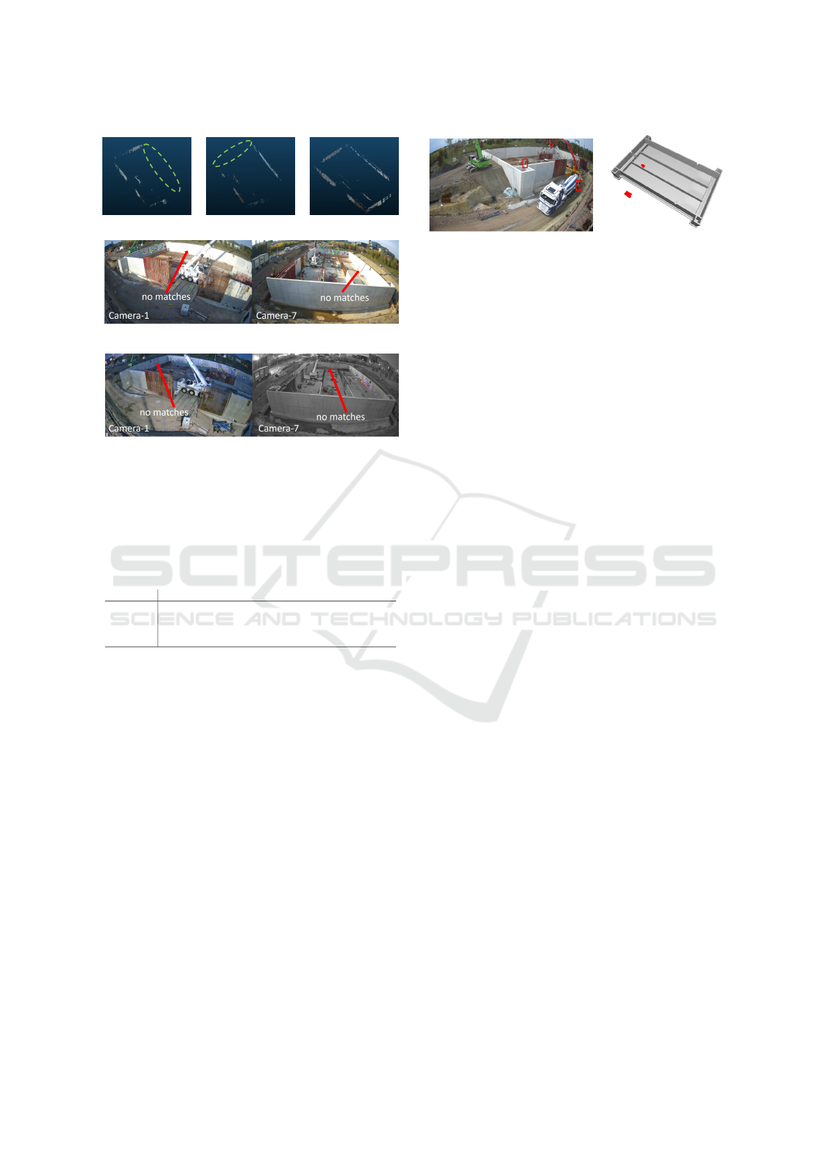
(a) (b) (c)
(d)
(e)
Figure 3: Dense model generated using (a) images cap-
tured during the daytime, (b) images captured at nighttime,
and (c) images captured during both daytime and nighttime.
Matches in image pairs captured (d) during the daytime and
(e) at nighttime.
Table 1: Statistics of the SfM reprojection error in centime-
ters (cm) of each viewpoint.
Viewpoint 1 2 3 4 5 6 7 8
min 1.85 2.07 1.02 1.91 2.98 2.04 1.31 1.4
mean 2.89 4.66 3.6 3.53 3.45 6.3 4.02 3.89
median 2.89 3.73 3.8 3.47 3.45 5.69 3.22 3.75
max 3.93 9.12 5.77 5.28 3.93 11.79 8.34 6.66
7 APPLICATION
Using the homography derived from aligning the
point cloud with the BIM model, we tracked activities
on the construction site by locating workers within
the BIM coordinate system. For a given timestamp,
we initiated by generating bounding boxes for work-
ers on images captured from various viewpoints (as
shown in Figure 4a). Subsequently, masks were cre-
ated for each of these images. Leveraging the shape-
from-silhouette method (Laurentini, 1994), we cre-
ated voxel volumes representing the workers. These
voxel volumes were transformed using the obtained
homography and were then visualized in conjunction
with the BIM model, as depicted in Figure 4b.
(a) (b)
Figure 4: Tracking activities using the homography ob-
tained in the alignment. (a) Bounding boxes of workers in
an image. (b) Visualizing voxel volumes of workers within
the BIM coordinate system.
8 CONCLUSION
In this study, we collected images from eight fixed
camera viewpoints at an actual construction site. To
spatially position construction activities within the
BIM coordinate system, we employed classical multi-
view stereo techniques to generate a 3D point cloud of
the as-built building, followed by aligning the point
cloud with the as-planned BIM model using a cloud
registration approach. We proposed an algorithm to
convert SfM reprojection error into a value with met-
ric units, resulting in a mean SfM reprojection error of
4.17cm. This result is considered acceptable within
the construction sector. We further visualized the con-
struction activities by creating voxel volumes and in-
tegrating them with the BIM model using the result of
the alignment.
REFERENCES
Ahmed, S. (2019). A Review on Using Opportunities of
Augmented Reality and Virtual Reality in Construc-
tion Project Management. Organization, Technology
and Management in Construction: an International
Journal, 11:1839 – 1852.
Arun, K. S., Huang, T. H., and Blostein, S. D. (1987). Least-
squares fitting of two 3-D point sets. IEEE Transac-
tions on Pattern Analysis and Machine Intelligence,
PAMI-9(5):698–700.
Azhar, S. (2011). Building information modeling (BIM):
Trends, benefits, risks, and challenges for the AEC in-
dustry. Leadership and management in engineering,
11(3):241–252.
Barnes, C., Shechtman, E., Finkelstein, A., and Goldman,
D. B. (2009). PatchMatch: A randomized correspon-
dence algorithm for structural image editing. ACM
Trans. Graph., 28(3):24.
Bay, H., Tuytelaars, T., and Van Gool, L. (2006). SURF:
Speeded Up Robust Features. In European Confer-
ence on Computer Vision, pages 404–417. Springer.
Besl, P. J. and McKay, N. D. (1992). A Method for Regis-
Multi-View 3D Reconstruction for Construction Site Monitoring
475

tration of 3-D Shapes. IEEE Transactions on Pattern
Analysis and Machine Intelligence, 14(2):239–256.
Bleyer, M., Rhemann, C., and Rother, C. (2011). Patch-
match stereo-stereo matching with slanted support
windows. In BMVC, volume 11, pages 1–11.
Chetverikov, D., Svirko, D., Stepanov, D., and Krsek, P.
(2002). Robust Euclidean alignment of 3-D point sets:
the trimmed iterative closest point algorithm. Image
and Vision Computing, 20(12):1071–1077.
DeTone, D., Malisiewicz, T., and Rabinovich, A. (2018).
SuperPoint: Self-Supervised Interest Point Detection
and Description. In Conference on Computer Vision
and Pattern Recognition, pages 224–233.
Eggert, D. W., Lorusso, A., and Fisher, R. B. (1997). Esti-
mating 3-D Rigid Body Transformations: A Compar-
ison of Four Major Algorithms. In Computer Vision
and Pattern Recognition, 1997. Proceedings., 1997
IEEE Computer Society Conference on, pages 699–
704. IEEE.
Fischler, M. A. and Bolles, R. C. (1981). Random sample
consensus: a paradigm for model fitting with appli-
cations to image analysis and automated cartography.
Communications of the ACM, 24(6):381–395.
Furukawa, Y., Hern
´
andez, C., et al. (2015). Multi-view
stereo: A tutorial. Foundations and Trends® in Com-
puter Graphics and Vision, 9(1-2):1–148.
Golparvar-Fard, M., Pe
˜
na-Mora, F., and Savarese, S.
(2009). D4AR–a 4-dimensional augmented reality
model for automating construction progress monitor-
ing data collection, processing and communication.
Journal of information technology in construction,
14(13):129–153.
Hartley, R. and Zisserman, A. (2003). Multiple view geom-
etry in computer vision. Cambridge university press.
Hartley, R. I. (1997). In defense of the eight-point algo-
rithm. IEEE Transactions on pattern analysis and ma-
chine intelligence, 19(6):580–593.
Karsch, K., Golparvar-Fard, M., and Forsyth, D. (2014).
ConstructAide: analyzing and visualizing construc-
tion sites through photographs and building models.
ACM Transactions on Graphics (TOG), 33(6):1–11.
Khalid Masood, M., Aikala, A., Sepp
¨
anen, O., Singh, V.,
et al. (2020). Multi-Building Extraction and Align-
ment for As-Built Point Clouds: A Case Study With
Crane Cameras.
Kim, C., Ju, Y., Kim, H., and Kim, J. (2009). Resource man-
agement in civil construction using RFID technolo-
gies. In Proceedings of the 26th International Sym-
posium on Automation and Robotics in Construction
(ISARC 2009), Austin, TX, USA, volume 2427, page
105108. Citeseer.
Kim, D., Liu, M., Lee, S., and Kamat, V. (2019). Re-
mote proximity monitoring between mobile construc-
tion resources using camera-mounted UAVs. Automa-
tion in Construction.
Laurentini, A. (1994). The visual hull concept for
silhouette-based image understanding. IEEE Trans-
actions on pattern analysis and machine intelligence,
16(2):150–162.
LeCun, Y., Bengio, Y., and Hinton, G. (2015). Deep learn-
ing. Nature, 521(7553):436–444.
Longuet-Higgins, H. C. (1981). A computer algorithm for
reconstructing a scene from two projections. Nature,
293(5828):133–135.
Lowe, D. G. (2004). Distinctive image features from scale-
invariant keypoints. International journal of computer
vision, 60:91–110.
Ma, J., Jiang, X., Fan, A., Jiang, J., and Yan, J. (2021).
Image matching from handcrafted to deep features:
A survey. International Journal of Computer Vision,
129:23–79.
Mahami, H., Nasirzadeh, F., Hosseininaveh Ahmadabadian,
A., and Nahavandi, S. (2019). Automated progress
controlling and monitoring using daily site images and
building information modelling. Buildings, 9(3):70.
Oh, S.-W., Chang, H.-J., Kim, Y.-S., Lee, J., and Kim, H.-s.
(2004). An Application of PDA and Barcode Technol-
ogy for the Improvement of Information Management
in Construction Projects.
Pollefeys, M., Nist
´
er, D., Frahm, J.-M., Akbarzadeh, A.,
Mordohai, P., Clipp, B., Engels, C., Gallup, D., Kim,
S.-J., Merrell, P., et al. (2008). Detailed real-time ur-
ban 3d reconstruction from video. International Jour-
nal of Computer Vision, 78:143–167.
Rusinkiewicz, S. and Levoy, M. (2001). Efficient variants
of the ICP algorithm. In Proceedings Third Interna-
tional Conference on 3-D Digital Imaging and Mod-
eling, pages 145–152. IEEE.
Sami Ur Rehman, M., Shafiq, M. T., and Ullah, F.
(2022). Automated Computer Vision-Based Con-
struction Progress Monitoring: A Systematic Review.
Buildings, 12(7):1037.
Sarlin, P.-E., DeTone, D., Malisiewicz, T., and Rabinovich,
A. (2020). SuperGlue: Learning Feature Matching
with Graph Neural Networks. In European Confer-
ence on Computer Vision, pages 815–832.
Sch
¨
onberger, J. L. and Frahm, J.-M. (2016). Structure-
from-Motion Revisited. In Conference on Computer
Vision and Pattern Recognition (CVPR).
Sepasgozar, S., Lim, S., Shirowzhan, S., and Kim, Y. M.
(2014). Implementation of As-Built Information
Modelling Using Mobile and Terrestrial Lidar Sys-
tems. pages 876–883.
Tuttas, S., Braun, A., Borrmann, A., and Stilla, U.
(2017). Acquisition and consecutive registration
of photogrammetric point clouds for construction
progress monitoring using a 4D BIM. PFG–journal
of photogrammetry, remote sensing and geoinforma-
tion science, 85(1):3–15.
Xue, J., Hou, X., and Zeng, Y. (2021). Review of image-
based 3D reconstruction of building for automated
construction progress monitoring. Applied Sciences,
11(17):7840.
Zhang, J., Zhang, J., Mao, S., Ji, M., Wang, G., Chen,
Z., Zhang, T., Yuan, X., Dai, Q., and Fang, L.
(2021). GigaMVS: a benchmark for ultra-large-scale
gigapixel-level 3D reconstruction. IEEE Transac-
tions on Pattern Analysis and Machine Intelligence,
44(11):7534–7550.
VISAPP 2024 - 19th International Conference on Computer Vision Theory and Applications
476
