
AutoNav in C-L-U-E: A Baseline Autonomous Software Stack for
Autonomous Navigation in Closed Low-Speed Unstructured
Environments
Mohamed Sabry
1 a
, Amr Farag
2 b
, Bassem Magued
2 c
, Ahmed Mazhr
1 d
,
Amr El Mougy
3 e
and Slim Abdennadher
4 f
1
Computer Engineering Department, German University in Cairo (GUC), Cairo, Egypt
2
Mechatronics Engineering Department, German University in Cairo (GUC), Cairo, Egypt
3
Department of Computer Science and Engineering, American University in Cairo (AUC), Cairo, Egypt
4
Informatics & Computer Science, German International University, Cairo, Egypt
Keywords:
Autonomous Systems, Mapless Navigation, Unstructured Environment, Perception, LiDAR.
Abstract:
The development of Autonomous systems modules has been growing exponentially within the past few years
with various complex approaches. Most of these systems have some restrictions or dependencies on numerous
inputs. There are two main categories of these systems, Highway and Urban Road-Vehicle autonomous sys-
tems, and short-distance autonomous platforms. The short-distance category includes minipods and golfcars
that operate in closed environments such as residential compounds or university campuses. Various challenges
have been identified in both categories. A challenge example for Highways / Urban areas is controlling the
vehicle’s motion on high and moderate speeds. However, for closed campuses, the challenge is mainly in ma-
neuvering around high density pedestrians moving with low speeds and being able to avoid low pavements and
obstacles that may damage the platform, such as potholes. For this matter and given the increasing complexity
of modules-in-development, this paper proposes a low-complexity baseline map-less autonomous software
stack with a perception module capable of navigating closed campuses within unstructured environments. The
system is a simple one that requires 1 - 2 LiDARs as well as an input route to follow, which is inserted by
the user from offline Open Street Maps (OSM) data. The system runs fully on-board on a consumer grade PC
without the need for internet connectivity and has been tested successfully in various scenarios on campus at
the German University in Cairo (GUC), Egypt. The tests included pedestrian and obstacle avoidance as well as
emergency stopping with the capability of resuming and the following the preset global path before departure.
The proposed system is based on the golf-car platform at the GUC.
1 INTRODUCTION
The expanding research within the autonomous sys-
tems field has yielded various approaches and re-
searches to pursue task specific applications. Pur-
suing the best possible performance as well as the
increasing curiosity of knowing the ability of Deep
Learning (DL) to solve the tasks, modules, and sys-
a
https://orcid.org/0000-0002-9721-6291
b
https://orcid.org/0000-0001-6446-2907
c
https://orcid.org/0009-0006-6953-0482
d
https://orcid.org/0009-0002-5252-0633
e
https://orcid.org/0000-0003-0250-0984
f
https://orcid.org/0000-0003-1817-1855
tems have increased in complexity, and in case of
DL, the lack of repeatability of results or being non-
deterministic. Moving to the test cases and envi-
ronment setting, some researches focused on Urban
and Highway structured environments with Road-
Vehicles such as (Bansal et al., 2018). In this envi-
ronment, vehicles such as cars / buses are equipped
with mostly multi-modal sensor setups, in order to
obtain as much information as possible about the en-
vironment. 3D maps can also be used, as in (Kato,
2017). In addition, structured environments provide
helper information, such as traffic lights, road signs
and markings and color defined lanes. This informa-
tion facilitates the navigation of the aforementioned
systems. As a downside to having various complex
Sabry, M., Farag, A., Magued, B., Mazhr, A., El Mougy, A. and Abdennadher, S.
AutoNav in C-L-U-E: A Baseline Autonomous Software Stack for Autonomous Navigation in Closed Low-Speed Unstructured Environments.
DOI: 10.5220/0012295500003636
Paper published under CC license (CC BY-NC-ND 4.0)
In Proceedings of the 16th International Conference on Agents and Artificial Intelligence (ICAART 2024) - Volume 1, pages 189-197
ISBN: 978-989-758-680-4; ISSN: 2184-433X
Proceedings Copyright © 2024 by SCITEPRESS – Science and Technology Publications, Lda.
189

modules to run, the computational cost increases dra-
matically, increasing computational power. For the
other test case regarding the unstructured environ-
ments, which contain closed campuses, a lot of the
aforementioned helper information are absent, which
limits the choice of suitable modules. Given the case
of a university campus, road lanes would be scarce, as
well as road markings and traffic signs. Another chal-
lenge would be the lack of asphalt roads all together
making the operation in the same areas as pedestri-
ans, which denotes the existence of stair steps lead-
ing to buildings, benches, green areas as well as any
other miscellaneous objects that are uncommon in au-
tomated driving scenarios. For these challenges, this
test case differs greatly than urban / highway driv-
ing, as the systems here are expected to operate in
a relatively unorganised manner without lanes and
road edges. The navigation in this case is slow in
crowded environments with other traffic participants,
mostly pedestrians. Given the absence of road mark-
ings, such as pedestrian crossings, and the ability of
the pedestrians to move anywhere, the system has to
be prepared to maneuver safely on drivable surfaces
to reach the requested goal. The uncertainties that are
found in the aforementioned situation requires a ro-
bust autonomous system that is capable of detecting
any pedestrians and traffic participants as a first pri-
ority. The second priority would be detecting terrain
and miscellaneous objects that can be hazardous to
the maneuvering autonomous platform, such as pot-
holes and pavements. Finally, a flexible global path
generation to enable the navigation on areas that are
road-absent.
Accordingly, this paper proposes an automated
software stack that serves as a lightweight baseline
autonomous system that has a stable perception mod-
ule that is capable of navigating Closed Low-Speed
Unstructured Environments (AutoNav in CLUE). The
proposed system has a perception module that is capa-
ble of detecting very fine changes in terrain up to 4-5
cm to ensure the system can avoid all on campus haz-
ards. In addition, the safety system has multiple set-
tings to ensure a smooth maneuvering and emergency
stopping with sudden close encounters of 1–2 meters
in tight spaces. For the planning module, it has the
capability of taking sharp maneuvers in order to navi-
gate close quarter proximity to traffic participants and
obstacles on campus grounds. The proposed system
requires 1–2 LiDARs as well as an input route to fol-
low, which is based on a Graphical plot of an offline
OSM map (OpenStreetMap contributors, 2017). The
system runs fully offline on the on-board CPU and has
been tested successfully around the GUC campus
1
.
1
A video link with the proposed AutoNav in CLUE in motion
The remainder of this paper is organized as fol-
lows. Section 2 discusses the state-of-the-art present
in the literature. Section 3 discusses the proposed Au-
toNav in CLUE system in detail. The experimental
work is then introduced in Section 3 including the
implementation details, and the evaluation metrics in
Section 4. Section 5 shows the proposed algorithm
object classification results and the discussion. Fi-
nally, Section 6 includes concluding remarks and fu-
ture work.
2 RELATED WORK
This section discusses the state-of-the-art systems
presented in the previous literature regarding differ-
ent autonomous software stack types.
2.1 Systems Based on Sensor Fusion
Most of the developed software stacks integrated with
road vehicles are aimed for road testing within urban
structured environments as aforementioned, with mi-
nor exceptions with restrictions in operation. Multiple
approaches use different methods but with the same
multi-modal sensor architecture concept. Examples
include the work in (Thrun et al., 2006), which was
the winner in the DARPA Grand challenge in 2005,
which was a desert-like track environment. Boss
(Urmson et al., 2008) is another example, which won
in the DARPA Urban challenge in an urban-like en-
vironment in 2007 and focused on the urban driving
case. Another approach relies heavily on Radar Sen-
sors such as in (Ziegler et al., 2014), (Franke et al.,
2013) and (Dickmann et al., 2014), which makes it
possible to navigate normal roads. These approaches
however have numerous dependencies and sensors of
high costs that make them unfeasible to build in large
numbers or even being built in upstarting research
projects / companies.
2.2 Map-Less Navigation Systems
To avoid scalability issues with map-based au-
tonomous navigation, several researches pursued the
map-less approach. These approaches make use of
the environment structure for local perception. Most
of these approaches rely on camera images to de-
tect roads (Broggi and Berte, 1995) (Zhang et al.,
2009) (Alvarez et al., 2008), road boundaries (Seo
and Rajkumar, 2014) as well as lane markings (Liu
et al., 2008) (Aly, 2008). Given the problems that
can rise from varying illumination to say the least,
the performance is not optimal, specially in crowded
ICAART 2024 - 16th International Conference on Agents and Artificial Intelligence
190
environments. Other researches use LiDARs to de-
tect drivable regions (Ort et al., 2018). However,
most LiDAR-based approaches assume the existence
of local landmarks as prior knowledge, such as lane-
markings, which makes the scalability to new loca-
tions time-consuming. Other approaches combine the
use of online maps and local perception in order to
navigate semi-structured environments, such as (Ort
et al., 2019).
2.3 Low-Cost Systems
For systems that aim at the navigation of closed cam-
puses / residential compounds, the number, and type
of sensors used are usually less in numbers and cost.
An example can be seen as demonstrated in (Marin-
Plaza et al., 2019) and (Hussein et al., 2016), where a
golf car platform is used with a couple of sensors at-
tached. A main challenge with closed campus naviga-
tion is the association with dense pedestrian traffic as
aforementioned, which needs to be handled carefully
of to ensure their safety. Other systems such as (An-
war et al., 2019) utilize the approach of pre-mapped
areas and pointcloud matching to be able to navigate.
However, the sensitivity of the perception systems
in these systems have been tested on obstacles only
up to 20 cm in height, which is not sensitive enough
for detecting obstacles that can cause uncomfort for
riders or even damage to the vehicle on the long run.
In addition, these approaches require a 3D pointcloud
map / GridMap (GM) of the area to-be-traversed be-
forehand.
In this paper, the proposed AutoNav in CLUE is
applied within a low-cost system on a golf-cart plat-
form with the main aim of enhancing the detections
of pedestrians, difficult to detect pavements and any
other harmful miscellaneous objects that are not com-
mon in the urban / highway automated driving. The
proposed approach is a plug-and-play one with pro-
posed local perception and path planning modules and
uses the map-less navigation capabilities. This system
is a low cost, faster alternative to (Ort et al., 2019),
which aims for crowded area navigation with unfa-
miliar obstacles and immediate emergency reactions
to pedestrians within 1-2 meter range in the vicin-
ity of the platform. The proposed system is capa-
ble of navigating anywhere where OSM exists, which
makes its scalability easier compared to 3D mapped
approaches.
3 METHODOLOGY
In this section, the main components of the proposed
autonomous software stack are introduced. The flow
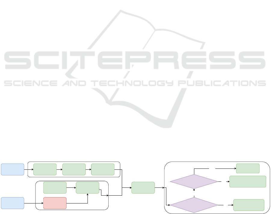
of the software stack can be seen in Figure 1.
3.1 System Inputs
For the system to operate efficiently, it requires two
LiDARs, one for local perception and one for obtain-
ing the odometry. For the odometry, A-LOAM was
used (Group, 3 28) as a method to track the motion
of the golf-car platform. For the global path acquisi-
tion, the osmnx library (Boeing, 2017) was altered to
view a local OSM file to the user, take in the selected
user path nodes and output the nodes in a format for
the proposed system to interpret. The odometry al-
gorithm is the only module used as is, the rest of the
proposed modules were implemented specifically for
the AutoNav in CLUE use case.
3.2 Global Path Selection
As a first stage, the users are presented with a map
view of the closed campus through a modified osmnx
library, which is extracted and saved offline prior to
the navigation. The users plot the desired path nodes
that they want the vehicle to follow on the map, with
respect to the map view as a reference. The idea of
the map is just to help the user to plot the desired
Initiate normal throttle
and steering
commands
Velodyne
VLP-16
LiDAR
Global Route
Selection
From OSM file
Odometry-
Based Motion
estimation
Node selection
for Heading
Calculation
Velodyne
VLP-32C
LiDAR
A-LOAM
LiDAR
Odometry
Edge Candidate
extraction
Drivable Area
Extraction
Drivable Node
Layout
Yes
No
Obstacle Close
to vehicle heading
Yes
No
Space available
to slow down
Reduce speed
gradually
Apply emergency
stopping with a 3 second
safety timeframe
Figure 1: An overview of the proposed AutoNav in CLUE architecture. Two Velodyne LiDARs are used for sensory informa-
tion input alongside the global route information from an OSM based approach as aforementioned. The data from the VLP-16
LiDAR is used with the perception modules until the non-occupied area is created alongside the node distribution. The data
from the VLP-32C LiDAR is only used with the A-LOAM odometry algorithm for real-time motion estimation. The motion
estimation is fused with the output from the local perception to select the best suited nodes to derive the heading from which
the control commands will be executed.
AutoNav in C-L-U-E: A Baseline Autonomous Software Stack for Autonomous Navigation in Closed Low-Speed Unstructured
Environments
191

path to-scale in meters for the vehicle to follow. This
approach is used as most of the use cases will be at
closed campuses with areas that do not have clear
paths, even in areas common with pedestrians. So any
map sections in OSM that do not have a path, the au-
tomatic global path generation like the (Rooy, 0 09)
or (Boeing, 2017) libraries will fail. The use of the
aforementioned libraries can only be applied in well
mapped areas to ensure the resultant path generated is
smooth enough for automated navigation. The sever-
ity level of the sharp turns may vary based on the ac-
curacy of the placed nodes in the acquired OSM map.
After the route selection, the chosen path is displayed
to the users as a confirmation step for the path geom-
etry. The generated path is represented in UTM coor-
dinates and denotes the global path to be followed by
the autonomous golf-cart.
3.3 Vehicle Motion Estimation
After selecting the global path, the system is fed the
UTM coordinates representing the global path as one
of the inputs. The global path acts as a guide for
the ego vehicle to follow until it reaches the user-
defined destination. In order to facilitate this function,
the vehicle’s motion has to be calculated in order to
know the real-time location with respect to the global
path. In addition, it is essential to know which node
to return to in the event of maneuvering around a dy-
namic / static obstacle. For this matter, LiDAR odom-
etry based on the work of (Group, 3 28) was chosen
to tackle the task of estimating the vehicle’s motion.
This is achieved by taking the cumulative odometry
translation and rotation and transforming the path rel-
ative to the vehicle. This creates an estimation of the
global path location for the user to visualize and for
the vehicle to set its next goal point, location, and
heading.
3.4 Global Path Update
For the global path update, the center of transforma-
tion of the path is set to be the automated test plat-
form, and the path gets transformed with respect to
the ego vehicle as seen in Figure 2 in subfigure a. This
is achieved by using the cumulative translation and
rotation estimates received from the A-LOAM algo-
rithm. As the vehicle moves autonomously, the global
path motion is visualized for the users with respect to
the center of the vehicle. The A-LOAM takes the data
from a 32 Layer LiDAR mounted on top of the golf-
car platform. This mounting choice is to increase the
area coverage of the LiDAR to include as many fea-
tures and landmarks as possible to get the best pos-
sible performance from the aforementioned odometry
algorithm.
3.4.1 Drift Compensation
Due to the drift generated from odometry as well as
minor inaccuracies between the OSM paths and the
real world paths, the global path can have an increased
shift and drift errors due to sharp consecutive turns,
dynamic traffic participants as well as high speeds
on uneven surfaces. To tackle this matter, a mo-
tion compensation module was applied to automati-
cally re-correct the location of the ego vehicle with
respect to the global path given it drifts away from the
autonomous vehicle further than a certain threshold.
This is applied based on the geometric constraints that
assumes that the chosen routes will always be placed
on drivable areas. Given the obvious assumption that
the ego vehicle will always be in the drivable area,
the approach is simple but proven to be effective in
reducing long term drift. The approach checks the
distance of the test platform from the global path in
each frame, given the distance increases more than a
predefined threshold, the system adds a constant mi-
nor compensation transformation to the current global
transformation to get the ego vehicle closer to the
global path.
3.5 Local Perception Module
For the local perception module, a single Velodyne
VLP-16 LiDAR is mounted on the golf car’s bonnet.
The LiDAR is mounted with a pitch angle of 14.2 de-
grees with a blind spot of 0.75 meters. The LiDAR
pointcloud produced from the aforementioned loca-
tion on the vehicle enables the detection of possible
hazards, miscellaneous objects or traffic participants
at close quarters. This mounting position also facil-
itates the detection of low pavements at close range.
Within crowded maneuvering, the proposed percep-
tion module will be capable of covering almost 120
degrees in front of the vehicle, which will be sufficient
for turning safely without colliding with obstacles on
the side of the vehicle. The range has been limited to
120 degrees to be compatible with the free area selec-
tion module later described in this paper. This is in
addition to detecting dynamic and static obstacles up
to 10 and 20 meters in front of the vehicle, depending
on the usage of short or long range setting.
3.5.1 The Grid Map Representation
The obtained pointcloud from the LiDAR is pro-
cessed and placed in a bird’s eye view (BEV) GM
with a size of 500 x 500 pixels, representing a total
ICAART 2024 - 16th International Conference on Agents and Artificial Intelligence
192

of 20 x 20 meters. The ego vehicle is in the center of
the grid in the short range setting and in the bottom
center in the long range setting.
3.5.2 Edge Candidates and Pavement Detection
To be able to detect objects and pavements in the
scene with the least possible computational power, all
objects that could obstruct or damage the ego vehi-
cle’s motion are detected as edge candidates. Edge
candidates are points in grid sections, where the devi-
ation of the height exceeds a certain threshold. Fur-
thermore, sections that satisfy the aforementioned
condition are further categorized in 4 further quarters
and, if the difference of the mean height of the points
between any 2 quarters exceeds a certain threshold,
the mean location of the points of the selected grid is
chosen to be an edge candidate. The edge candidates
are shown as green points in the GM, as seen in Figure
5 in subfigure b and in Figure 6, subfigure a.
Figure 2: In (a), an overview of the relation between the
ego vehicle location represented by the yellow circle in the
middle of the GM and the global path represented by the
thin white line. The short white line, connecting the yellow
circle and the global path, is the shortest Euclidean distance
to the global path. (b) shows the full system output, which
is trying to follow the Global path after maneuvering around
some obstacles. In both figures, the vehicle is at the middle
of the frame, facing forward.
3.5.3 Safe Non-Occupied Area Selection
After extracting the edge candidates, they are placed
on a 16 layer sector, which originates from the vehi-
cle location and represent the free area and are further
cropped based on the edge candidates. The processing
of the sectors start from the side of the vehicle to the
outermost sector layer. To simulate occluded areas in
the event that some sectors do not have any detected
edge candidate, the last known edge in the earlier sec-
tors are saved. Given their location, the following sec-
tor sections are cropped at the same point until new
edges are detected in them. An example can be seen
in Figure 8, where a cone can be seen in subfigure c on
the left and after the cone, there is free area. However,
given that within the full sector range there is no other
object seen, or a pavement edge detected, the location
of the edge node of the cone is replicated in the fol-
lowing sector sections with the same truncation. This
method helps significantly in orienting the heading of
the vehicle correctly towards the global path, as well
as ensuring that the vehicle always stays equidistant
from the leftmost and rightmost edges.
To be able to set the number of nodes to choose
from in each ring representation, nodes are placed
equidistantly with the following equation:
N
nodes
= int(abs(Min
R−B
− Max
R−B
) ∗ F) (1)
Where N
nodes
is the number of nodes per ring,
(Min
R−B
is the left most ring boundary and Max
R−B
is the right most ring boundary. F is scalar factor con-
verts the grid representation to real life meters.
To ensure a safe navigation route, a buffer of 1.5
meters is placed from the edges of the pavements de-
tected. The available nodes generated are removed in
the mentioned buffer area. 3
3.6 Path Planning
After generating the usable nodes, a cost function was
chosen to select the best node in each ring to create
the direction that the ego vehicle will take. The func-
tion is based on the node’s distance from the nearest
pavement to is as well as the distance from the goal
point. The chosen nodes are labeled as red as shown
in Figure 7 in figure b. 3
C
nodes
=
Constant
abs(P
Nearest
− node
x
)
(2)
C
node
= argmin(C
nodes
) (3)
Where C
nodes
is an array of the cost of each node,
P
Nearest
is an array of differences between the pave-
ment’s left and right edges and the node
x
3.7 Control
The main control modules were based on the longitu-
dinal and lateral control.
3.7.1 Lateral
In order to apply the proposed algorithm at the hard-
ware level, the generated scene heading direction
must be converted to steering angles, which should
then be converted to steering wheel angles. Simple
mapping is used to indicate the desired direction from
the generated scene. This is done by first extracting
the desired heading from the tangent of 1/4 distance
point of the 2nd degree polynomial curve representing
the desired path:
AutoNav in C-L-U-E: A Baseline Autonomous Software Stack for Autonomous Navigation in Closed Low-Speed Unstructured
Environments
193
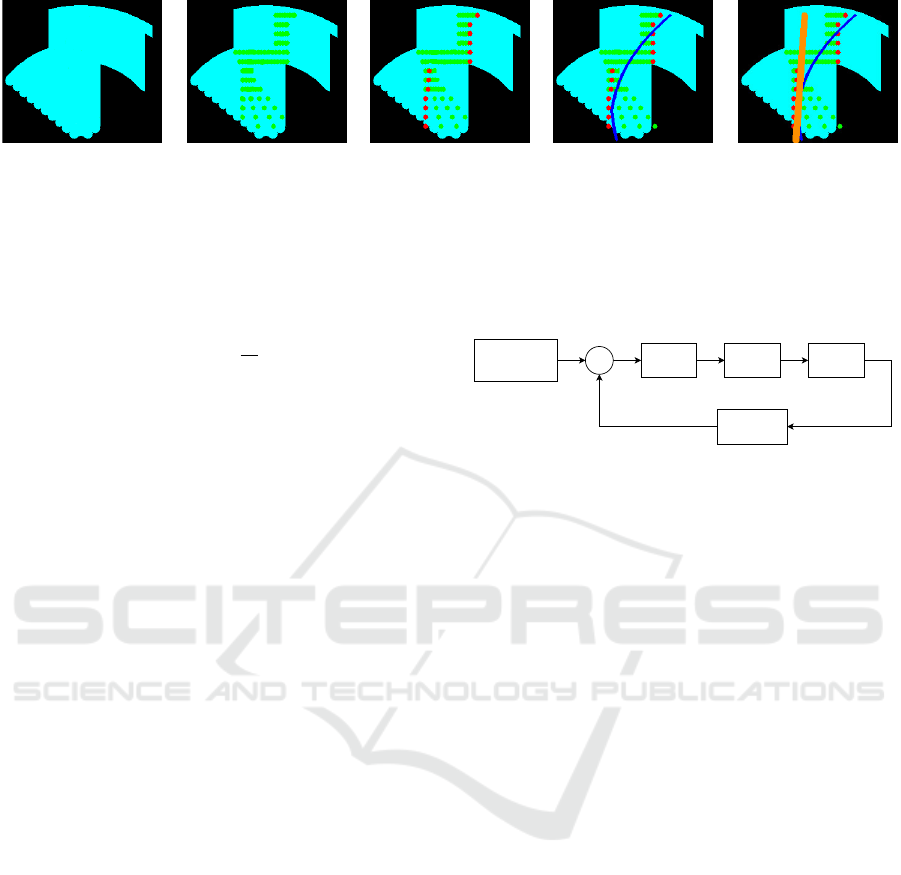
(a) (b) (c) (d) (e)
Figure 3: The figure explains in detail the 5 main steps that yield the final heading direction to be pursued by the vehicle. In
(a), the cyan represents the non-occupied free area. (b) shows the node distribution per sector slice based on the non-occupied
area shown as green dots. (c) shows the selected nodes in red, which adhere to equations 3 and 2. In (d), a second degree
polynomial is fitted on the chosen red nodes to get a base understanding of the heading extracted from the proposed software
stack. (e) shows the tangent calculated to the previously fitted curve. The angle of the tangent in orange denotes the final
heading the vehicle should follow. In the presented figures, the vehicle is at the bottom middle of the frame, facing forward.
slope =
d
y
d
x
(4)
ψ
des
=
(
tan(slope), if tan(slope) ≥ 0
tan(slope) + 180, if tan(slope) < 0
(5)
The desired heading is then mapped to the desired
steering angle. This mapping acts as a proportional
controller.
The output of this P controller is then converted to
a steering wheel angle by multiplying with a steering
ratio, which differs from one vehicle to another.
To overcome the uncertainties and disturbances of
the hardware vehicle model, an adapted Proportional
Integral Derivative (PID) control technique is used.
This is because the traditional PID control may not be
able to give the desired performance in a wide range
of longitudinal speeds or heading rates. There are
two main sets of PID gains; k
p
, k
i
and k
d
are pre-
defined, one set produces an aggressive performance
when the steering angle error is greater than a spe-
cific threshold to decrease the response time without
applying an excessive voltage on the steering motor.
Below this threshold, another set is activated to pro-
duce a smooth performance until the error converges
to a very small limit, at which the PID controller is de-
activated until the steering error increases. The deac-
tivation of the controller reduces the braking current,
which is drained by the steering motor. Note that the
feedback is taken from the steering wheel angle and
passes through a low pass filter to remove the signal
noise. The cutoff frequency is selected to remove the
noise as much as possible without affecting the re-
sponse time of the signal. Figure 4 shows the control
loop of the steering angle.
3.7.2 Longitudinal
For the longitudinal control, the vehicle operates at a
constant speed of 3–10 kph in the low speed testing
version, which is fed to the motor through a digital
PID
Controller
-
Low Pass Filter
steering wheel angle
Vehicle
Steering
+
Heading to Steering
Angle Converter
PID Gain
Adapter
Figure 4: The PID Control Loop.
potentiometer. Given no obstacle is detected in close
range, or an object that exists in the vicinity, the plat-
form will slow down accordingly while maneuvering.
4 EXPERIMENTAL WORK
4.1 System Setup
All the experiments were conducted on the golf car
platform at the self-driving car lab at the GUC.
The system is based on a Velodyne VLP-16 LiDAR
mounted on the bonnet of the platform to reduce the
blind spot of the vehicle for perception. An addi-
tional Velodyne VLP-32C LiDAR is mounted on top
of the platform to be used with the odometry mod-
ule as aforementioned. The proposed approach as of
writing this paper is implemented in Python, using
OpenCV, NumPy, and ROS noetic. All experiments
and tests were carried out on a computer with an Intel
i7-8800K 6-core processor using 32GB of RAM, run-
ning Ubuntu version 20.04, with a GTX 1060 GPU.
For the controllers, three PCB boards with an Arduino
Nano each, are integrated with the system electronics.
The steering and brakes boards are connected to a 24
V, 80 W motor each through a 43 A motor driver. For
the throttle board, it is connected directly to the golf
car systems and feeds the data through a digital po-
tentiometer.
The evaluation of the proposed prototype system
was done on the GUC campus, utilizing routes with
different lengths and difficulties. An example can be
ICAART 2024 - 16th International Conference on Agents and Artificial Intelligence
194
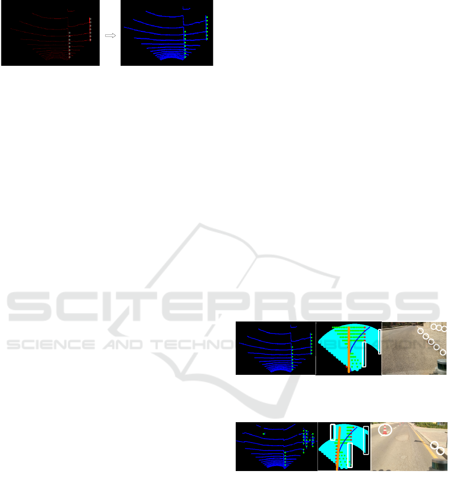
(a) (b)
Figure 5: The figure shows the visual modification to the
output of the system to be better interpreted. In both fig-
ures, the vehicle is at the bottom middle of the frame, fac-
ing forward. The visualization (b) will be used throughout
the system output representation. In (a), the red curves and
points represent the LiDAR perception and the circled green
dots represent the detected edges from the proposed LiDAR
perception module. In (b), the input LiDAR data has been
morphologically dilated and converted to blue, and the edge
points have also been enhanced to be more visually clear.
seen in Figure 1.
Other testing routes included maneuvering around
roundabouts, 90 degree turns as well as simple
straight paths. Tests were also conducted with and
without traffic participants in the vicinity of the test-
platform, with pedestrians suddenly running in front
of the platform to test the reaction of the system.
It was ensured that the test routes also contain
some challenging situations with very low pavements
of 4-5 cm, potholes and no road markings to test the
robustness of the software stack as well as the pro-
posed local perception module.
5 RESULTS AND DISCUSSION
In this section, the results of the proposed software
stack on the GUC golf car platform will be discussed
with qualitative and quantitative measures.
5.1 Results
During the scenarios tackled by the vehicle, the routes
were traversed successfully maneuvering dynamic
and static obstacles in the scene, as well as detect-
ing pavements and potholes as low as 4-5 cm along
the way. The given performance shows an adequate
performance from sparse points falling on pavements
represented in 8 rings from the 16 of the used LiDAR.
From the maneuvers, it was concluded that all the
obstacles in the scene can be avoided, including cones
as well as any object detectable by the LiDAR, has a
high gradient and as low as 4-5 cm. The proposed sys-
tem results can be obtained given AutoNav in CLUE.
The proposed system was also capable of auto-
matically slow down when approaching sloped roads
going downhill, which ensures passenger comfort in
the process.
For the performance of the system, even though a
relatively slow programming language, python, with-
out the optimizations and advantages of C++ is used
at the time of writing this paper, utilizing two LiDARs
and only the CPU, the performance was in the range
of 12–15 FPS. Given the migration to C++, the sys-
tem is expected to pass the 20 FPS mark.
5.1.1 Qualitative Results
For some qualitative results, Figures 6, 7, 8 and 9
show some of the challenges that the system was able
to overcome. In Figure 6, the system is capable of
detecting approximately a 10 cm pavement as well as
the wall on the right as seen in (c). (a) shows the
Bird’s Eye View (BEV) of the LiDAR, with the edges
detected in green. In (b), a view of the system output
can be seen. In (a), the edges detected by the pro-
posed algorithm can be seen in green. White circles
and rectangles denote the edges detected across the
BEV, as well as the approximate respective detection
on the camera view. For Figure 7, in subfigures (b)
and (c) white circles and rectangles denote the edges
detected across the BEV as well as the approximate
respective detection on the camera view. In subfigure
(a), the edges detected by the proposed algorithm can
be seen in green.
(a) (b) (c)
Figure 6: The figure shows the system output in real-time
for static objects, namely pavements and border walls.
(a) (b) (c)
Figure 7: The figure shows the output of the system (Fig-
ures a and b) with a relatively low pavement (4-5 cm) as
well as a cone. This is of utmost importance, as this ensures
the proposed system will operate in a solid manner without
relying on classifications of pedestrians or other traffic par-
ticipants.
5.1.2 Quantitative Results
For in-depth analysis of the performance of the pro-
posed system, the scenario shown in Figure 12 will be
discussed in detail. The location shown in Figure 12
AutoNav in C-L-U-E: A Baseline Autonomous Software Stack for Autonomous Navigation in Closed Low-Speed Unstructured
Environments
195
(a) (b) (c)
Figure 8: The figure shows the output of the system given
regular well-known obstacles (vehicles). White circles and
rectangles in (b) and (c) denote the edges detected across
the BEV as well as the approximate respective detection on
the camera view. In (a), the edges detected by the proposed
algorithm can be seen in green.
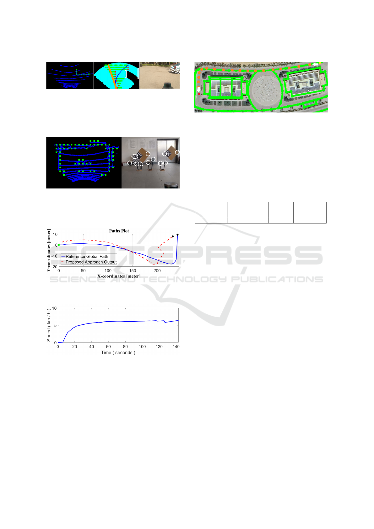
(a) (b)
Figure 9: The figure shows the output of the system indoors,
denoting the possibility of applying the system in indoor
environments as it can detect any object with a substantial
inclination, given it can be detected by the LiDAR sensor.
Figure 10: The figure shows the path that the system tra-
versed in red, compared to the given guide path from the
OpenStreetMap map section in blue.
Figure 11: The figure shows the speed profile of the plat-
form as the AutoNav system traverses the path. It can be
noted that the vehicle accelerates smoothly up to 6+ km/h.
As any detected object starts entering the vicinity of the ve-
hicle, the system slows down accordingly, then speeds back
up. The maneuver can be seen around the 125-second mark
in the Figure.
has no road lanes or helper traffic signs. In addition,
there are multiple directions that can confuse the sys-
tem, going with the roundabout or continuing straight
ahead. Furthermore, as seen in the aforementioned
figure, it can be seen that the OSM node network
can sometimes be misaligned with the real world road
Figure 12: The figure shows the location of one of the test
scenarios. The satellite view from Google Maps (Svenner-
berg, 2010) is shown with the OpenStreetMap node network
overlaid in green. It can be seen that there is some inaccu-
racy between the real world roads and the OSM node net-
work layout. The test scenario in this case starts from the
top right yellow dot, continues along the orange waypoints
and stops at the destination at the red dot on the bottom left.
Table 1: The following table shows some statistics from
the test path traversed as seen in Figure 12. The transla-
tion error deviation mainly due to the minor inaccuracies in
OpenStreetMap compared to the real world roads.
Total Distance
(m)
Standard Deviation
Translational Error
(%)
Top Speed
(km/h)
Average Speed
(km/h)
264.22 7.011 6.412 5.02
networks. With all the aforementioned obstacles, the
AutoNav in CLUE system was capable of realigning
with the OSM misalignment and successfully reach
the vicinity of the destination, as can be seen in Fig-
ure 10. With the respective speed profile seen in Fig-
ure 11, a relatively smooth acceleration can be seen
accompanied by slowing down whenever a detected
obstacle comes within the hazard range of the percep-
tion system.
5.2 Discussion
The main contribution of this paper is a baseline au-
tomated software stack that requires simple input data
that is able to perform AutoNav in CLUE. The pro-
posed software stack, is based on a simple map-less
navigation system, a perception system and path plan-
ning modules that enable close quarter navigation and
detection and avoidance of miscellaneous obstacles
as well as low-pavements. The system was able to
successfully navigate crowded closed campuses based
solely on local perception, odometry and initially,
a global path from an OSM approach. This com-
bination allows the system to operate almost any-
where with a 2D map available. The work can be
further extended to enable Vehicle-to-Vehicle (V2V)
and Vehicle-to-everything (V2X) communication for
an IoT based network for multi-vehicle operation, as
well as further applying automated pickup functions
to act as an autonomous taxi.
ICAART 2024 - 16th International Conference on Agents and Artificial Intelligence
196

5.3 Limitations
The proposed software stack of the system has few
limitations. Running the proposed system in snowy /
rainy weather conditions may cause the AutoNav in
CLUE system to move very slowly or even make the
system stationary. This is due to the LiDARs detect-
ing rain drops or snowflakes as continuous dynamic
objects moving very close to the test platform.
6 CONCLUSIONS
This paper proposed an autonomous software stack
for AutoNav in CLUE prototype. The system is a
baseline one, with ensured stable performance suited
for close quarter encounters with medium to high den-
sity presence of traffic participants, especially pedes-
trians. The proposed system is based on map-less
navigation and only utilizes two Velodyne LiDAR
sensors. The system is light with a performance range
of 12–15 FPS with dual LiDARs and using Python.
The composition of multiple lightweight modules en-
ables the prototype proposed software stack to nav-
igate dynamically in crowded, unstructured environ-
ments with CPU utilization only. The prototype per-
formed efficiently tackling the predefined use case
with satisfactory results in multiple test cases in dif-
ferent routes.
REFERENCES
Alvarez, J. M., Lopez, A., and Baldrich, R. (2008).
Illuminant-invariant model-based road segmentation.
In 2008 IEEE Intelligent Vehicles Symposium, pages
1175–1180. IEEE.
Aly, M. (2008). Real time detection of lane markers in ur-
ban streets. In 2008 IEEE intelligent vehicles sympo-
sium, pages 7–12. IEEE.
Anwar, A., Elmougy, A., Sabry, M., Morsy, A., Rifky, O.,
and Abdennadher, S. (2019). Autonomous vehicle
prototype for closed-campuses. In Joint International
Conference on Design and Construction of Smart City
Components, pages 339–348. Springer.
Bansal, M., Krizhevsky, A., and Ogale, A. (2018).
Chauffeurnet: Learning to drive by imitating the
best and synthesizing the worst. arXiv preprint
arXiv:1812.03079.
Boeing, G. (2017). Osmnx: A python package to work with
graph-theoretic openstreetmap street networks. Jour-
nal of Open Source Software, 2(12).
Broggi, A. and Berte, S. (1995). Vision-based road detec-
tion in automotive systems: A real-time expectation-
driven approach. Journal of Artificial Intelligence Re-
search, 3:325–348.
Dickmann, J., Appenrodt, N., and Brenk, C. (2014). Mak-
ing bertha. IEEE spectrum, 51(8):44–49.
Franke, U., Pfeiffer, D., Rabe, C., Knoeppel, C., Enzweiler,
M., Stein, F., and Herrtwich, R. (2013). Making bertha
see. In Proceedings of the IEEE International Confer-
ence on Computer Vision Workshops, pages 214–221.
Group, H. A. R. ([Last Accessed 2019-03-28]). A-loam.
Hussein, A., Mar
´
ın-Plaza, P., Mart
´
ın, D., de la Escalera, A.,
and Armingol, J. M. (2016). Autonomous off-road
navigation using stereo-vision and laser-rangefinder
fusion for outdoor obstacles detection. In 2016 IEEE
Intelligent Vehicles Symposium (IV), pages 104–109.
IEEE.
Kato, S. (2017). “autoware.
Liu, W., Zhang, H., Duan, B., Yuan, H., and Zhao, H.
(2008). Vision-based real-time lane marking detection
and tracking. In 2008 11th International IEEE Con-
ference on Intelligent Transportation Systems, pages
49–54. IEEE.
Marin-Plaza, P., Hussein, A., Martin, D., and de la Escalera,
A. (2019). Icab use case for ros-based architecture.
Robotics and Autonomous Systems, 118:251–262.
OpenStreetMap contributors (2017). Planet dump re-
trieved from https://planet.osm.org . https://www.
openstreetmap.org.
Ort, T., Murthy, K., Banerjee, R., Gottipati, S. K., Bhatt,
D., Gilitschenski, I., Paull, L., and Rus, D. (2019).
Maplite: Autonomous intersection navigation without
a detailed prior map. IEEE Robotics and Automation
Letters, 5(2):556–563.
Ort, T., Paull, L., and Rus, D. (2018). Autonomous vehi-
cle navigation in rural environments without detailed
prior maps. In 2018 IEEE international conference on
robotics and automation (ICRA), pages 2040–2047.
IEEE.
Rooy, N. ([Last Accessed 2021-10-09]). Taxicab.
Seo, Y.-W. and Rajkumar, R. R. (2014). Detection and
tracking of boundary of unmarked roads. In 17th In-
ternational Conference on Information Fusion (FU-
SION), pages 1–6. IEEE.
Svennerberg, G. (2010). Beginning google maps API 3.
Apress.
Thrun, S., Montemerlo, M., Dahlkamp, H., Stavens, D.,
Aron, A., Diebel, J., Fong, P., Gale, J., Halpenny,
M., Hoffmann, G., et al. (2006). Stanley: The robot
that won the darpa grand challenge. Journal of field
Robotics, 23(9):661–692.
Urmson, C., Anhalt, J., Bagnell, D., Baker, C., Bittner, R.,
Clark, M., Dolan, J., Duggins, D., Galatali, T., Geyer,
C., et al. (2008). Autonomous driving in urban envi-
ronments: Boss and the urban challenge. Journal of
Field Robotics, 25(8):425–466.
Zhang, G., Zheng, N., Cui, C., Yan, Y., and Yuan, Z. (2009).
An efficient road detection method in noisy urban en-
vironment. In 2009 IEEE Intelligent Vehicles Sympo-
sium, pages 556–561. IEEE.
Ziegler, J., Bender, P., Schreiber, M., Lategahn, H., Strauss,
T., Stiller, C., Dang, T., Franke, U., Appenrodt, N.,
Keller, C. G., et al. (2014). Making bertha drive—an
autonomous journey on a historic route. IEEE Intelli-
gent transportation systems magazine, 6(2):8–20.
AutoNav in C-L-U-E: A Baseline Autonomous Software Stack for Autonomous Navigation in Closed Low-Speed Unstructured
Environments
197
