
DecSup: An Architecture Description Language for Specifying and
Simulating the Decision Support System Architectures
Mert Ozkaya
1
, Mehmet Alp Kose
2
and Egehan Asal
3
1
Yeditepe University, Department of Computer Engineering, Istanbul, Turkey
2
Independent Researcher, Istanbul, Turkey
3
DFDS, Istanbul, Turkey
Keywords:
Architecture Description Languages, Event-Driven Architectures, Decision Support, Simulation, Modelica.
Abstract:
Decision support systems (DSSs) have been existing for automating the decision making processes and reach-
ing the optimum decision(s) using a data set in the quickest way. Despite the importance of DSSs, no any
architecture description language (ADL) have been proposed for the high-level specifications and analysis of
DSS architectures. So, in this paper, we propose a new ADL called DecSup which enables for the graphical
specifications of DSS architectures in terms of the problem, diagnosis, and action components that interact
with each other in an event-based manner. Problem components represent the domain data sets whose initiali-
sation/change trigger an event for the diagnosis component. Diagnosis components include pattern predicates
for making diagnosis using the events occurring. Whenever a diagnosis is made, another event is emitted for
the action components to take any necessary actions. DecSup is supported with a prototype toolset for speci-
fying the architecture models and transforming models in the Modelica simulation language. The transformed
Modelica code can be used to simulate the DSS architecture models and test the architectural decisions via
some scenarios. We evaluated DecSup using a case-study based on the contagious respiratory illnesses (i.e.,
cold, flu, and Covid-19).
1 INTRODUCTION
Architecture description languages (ADLs) have been
existing since the early nineties for enabling the high-
level specifications of software architectures (Gar-
lan and Shaw, 1994; Perry and Wolf, 1992). With
ADLs, high-level architectural design decisions can
be specified and reasoned about in the early design
stage so as to better analyse the requirements and
thus lead the development of quality software sys-
tems (Ozkaya, 2018b; Clements, 1996; Medvidovic
and Taylor, 2000). Some ADLs are supported with
tools, through which architectural decisions can be
analysed, simulated, proved for correctness, checked
for quality properties (e.g., performance, reliability,
and security), and further transformed into code.
ADLs may differ depending on their scope -
general-purpose ADLs and domain-specific ADLs
(Taylor et al., 2010). General-purpose ADLs (e.g.,
Wright (Allen and Garlan, 1997), Darwin (Magee
and Kramer, 1996), XCD (Ozkaya and Kloukinas,
2014), etc.) offer general-purpose notation sets for
specifying the architectures of any types of software
systems, while domain-specific ADLs (e.g., AADL
(Feiler et al., info)) support the architectural speci-
fications of systems at particular domains (e.g., the
embedded systems domain). With domain-specific
ADLs, it becomes possible to address any issues spe-
cific to a particular problem domain at an architectural
level and perform further operations such as analysis,
simulation, code generation, etc.
In this study, a novel domain-specific ADL is pro-
posed for the high-level specifications of decision
support system (DSSs) architectures. DSSs are in-
tended for enabling the computers to make decisions
for any given problems by using the existing data
(Holsapple, 2008; Alexander, 2002). Today, DSSs
are used in almost all the industries to automate the
decision making processes including healthcare, fi-
nance, manufacturing, defense, railway, and disas-
ter management, etc. While the number of DSS
tools has been ever-increasing, the DSS tools devel-
oped may not be the one desired by the domain ex-
perts, as it is likely for the developers to get the re-
quirements in an incomplete, incorrect, or inconsis-
tent way (Humphrey, 2006; Charette, 2005; Hussain
Ozkaya, M., Kose, M. and Asal, E.
DecSup: An Architecture Description Language for Specifying and Simulating the Decision Support System Architectures.
DOI: 10.5220/0012231200003645
Paper published under CC license (CC BY-NC-ND 4.0)
In Proceedings of the 12th International Conference on Model-Based Software and Systems Engineering (MODELSWARD 2024), pages 89-98
ISBN: 978-989-758-682-8; ISSN: 2184-4348
Proceedings Copyright © 2024 by SCITEPRESS – Science and Technology Publications, Lda.
89

and Mkpojiogu, 2016). Also, inadequate handling
of the requirements and architectural design stages
lead to the issue called architectural mismatch (Garlan
et al., 1995), which causes the inability of composing
a set of components to a successful system due to the
wrong assumptions made about the interactions and
behaviour of the components.
Despite many ADLs existing in the literature
which focus on different domains and problems, no
ADL supports the specifications of high-level DSS
architectures and their reasoning as discussed in Sec-
tion 2. None of the existing ADLs provide a specific
architectural notation set that can be suited for the
DSS architecture modeling. Therefore, we propose
in this paper a new ADL called DecSup for specify-
ing the DSS architectures and a prototype toolset for
demonstrating our language and performing the anal-
ysis and simulation of DSS architecture models. With
DecSup, DSS architectures can be specified in terms
of the problem, diagnosis, and action components that
can interact with each other in an event-based man-
ner. The DSS architectures specified with DecSup can
automatically be transformed in accordance with the
Modelica simulation language (Fritzson, 2004)
1
, and
the transformed Modelica models can be simulated
via the simulators supporting Modelica
2
.
In the rest of the paper, we firstly discuss the simi-
lar languages in the literature. Then, we introduce the
language definition and the tool support for DecSup
subsequently. Next, we introduce our case study that
we intend to use for evaluating the language and its
toolset. Lastly, we give the conclusion.
2 RELATED WORK
In the literature, many ADLs have been proposed,
each of which has contributed to the field on different
aspects with some interesting features. We discussed
several of those ADLs in our previous work in terms
of a comprehensive set of requirements that are cate-
gorised as the language definition, language features,
and tool support (Ozkaya, 2018b). In other works,
we further analysed domain-specific modeling lan-
guages including the UML-based modeling languages
(Ozkaya, 2018a) and IoT-based modeling languages
(Arslan et al., 2023). However, while there exist some
languages that support the decision making processes
in some particular domains, none of the existing lan-
guages support the high-level specifications of DSS
architectures regardless of any problem domains and
the simulation of the high-level design decisions.
1
Modelica web-page: https://modelica.org/
2
Modelica simulators: https://modelica.org/tools.html
Besides the ADLs, the literature also includes
some meta-modeling approaches that promote the ap-
plication of model-driven engineering for the deci-
sion making processes and propose a set of con-
cepts and relationships specific to particular domains
(e.g., disaster management, manufacturing, health-
care, and software cost estimation) (Othman and Bey-
doun, 2013; Porres et al., 2008; Almeida et al., 2021;
Weston, 2012). However, those approaches do not
propose a language with concrete notation set. Also,
none of those approaches focus on the high-level
specifications of DSS architectures regardless of any
domain concerns and their simulation.
The literature further includes event processing
languages (EPLs), through which the events repre-
senting the domain data can be specified and com-
posed to more complex events using event patterns
(Boubeta-Puig et al., 2014). Event patterns can be
used for making any diagnosis based on the events
gathered from the environment. EPLs can be stream-
based or rule-based and supported by the tools that
can transform models into executable event-driven
applications (e.g., the Esper
3
stream-based language
and the Drools Fusion
4
rule-based language). How-
ever, EPLs do not aid in specifying the DSS archi-
tectures in terms of a specific set of component and
connector types as is the case with our DecSup ADL.
3 DecSup’S DEFINITION
To define the concepts for DecSup, we got inspired
from Dunkel et al.’s work on proposing a reference
architecture for the event-driven DSSs (Dunkel et al.,
2011). Figure 1 depicts the meta-model diagram for
DecSup, which shows the concepts corresponding to
the architectural component and connector types, the
attributes that those types are composed of, and the
multiplicity constraints. So, the language definition
consists of three types of main components (i.e., prob-
lem, diagnosis, and action) and two types of connec-
tors (problem-to-diagnosis and diagnosis-to-action).
3.1 Problem Component Type
We consider each DSS as addressing some problems
and requiring problem-related data from their envi-
ronment so that the DSS can determine the occurrence
of the problem, make some diagnosis and take any
necessary actions. The Problem component type here
3
Esper: https://www.espertech.com/esper/
4
Drools Fusion: https://docs.drools.org/5.6.0.Final/
drools-fusion-docs/html/
MODELSWARD 2024 - 12th International Conference on Model-Based Software and Systems Engineering
90
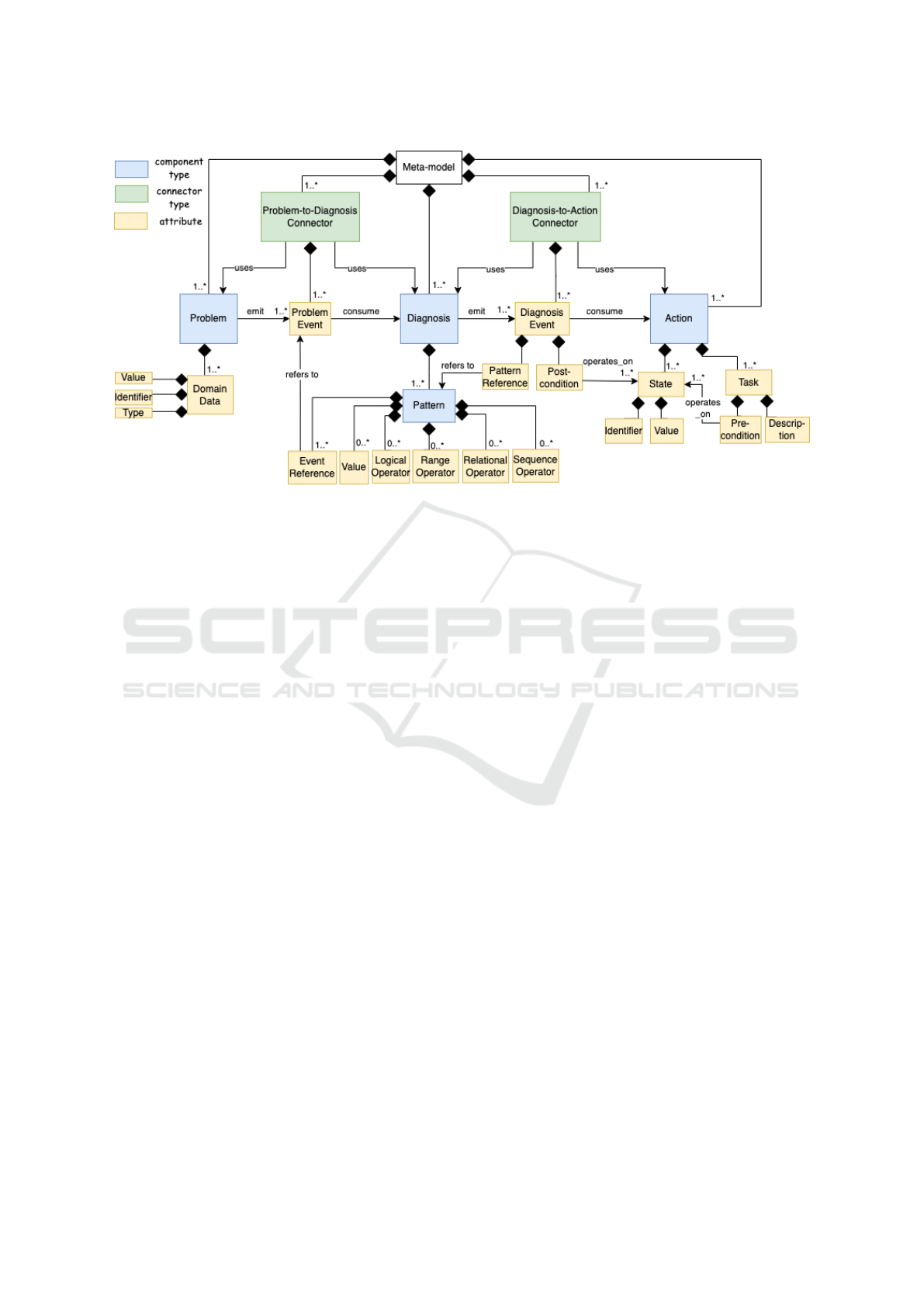
Figure 1: DecSup’s meta-model diagram.
is used for specifying the domain data set for an ex-
isting problem. Note that any DSS architecture may
include multiple components of the problem compo-
nent type, each of which is concerned with a particu-
lar problem that the DSS considers for its decisions.
A problem component is composed of one or more
domain data variables, which are specified with a data
type (e.g., int and boolean), identifier, and data value.
Note that as discussed in Section 3.4, whenever a data
variable is initialised or get its value changed, this
triggers an event to be occurring and emitted by a di-
agnosis component. An event triggered here conveys
the data value of the associated data variable.
Figure 2 shows the use of DecSup’s graphical no-
tation set for specifying a problem component. Any
problem component is specified with a red circle
(“P”). Whenever the problem component symbol is
clicked, a dialog box opens for specifying (i) the prob-
lem identifier, (ii) informal description text, and (iii)
the domain data list. Whenever any domain data in
the data list is clicked, a new user interface opens for
specifying the type, identifier and value of the data.
3.2 Diagnosis Component Type
Whenever any problem occurs that lead to a set of do-
main data variables assigned with new/changed val-
ues, a diagnosis needs to be made using those data. A
Diagnosis component type is for specifying the diag-
nosis descriptions and pattern predicates that are used
for making detections from the problem data avail-
able. Any DSS architecture may consist of one or
more diagnosis components each of which is con-
cerned with a cohesive set of detections.
Any diagnosis component is composed of one or
more pattern components. A pattern component type
herein is used for specifying a pattern model that de-
scribes a predicate statement whose satisfaction (e.g.,
evaluating to true) indicates a diagnosis made from
the problem(s) and triggers an event for an action.
A pattern model is specified with one or more
event references that refer to the events generated by
the problem components. Note here that each event
used in a pattern model is essentially the representa-
tion of a domain data variable that is initialised and
gets their value changed. The event references are
used for comparing their data variables with some
values using relational operators (e.g., greater than,
less than, equal) or range operator (i.e., checking any
event data is within a particular range). The com-
parison statements of different events are logically
composed using logical operators (i.e., AND, OR, and
NOT). A pattern may also check for the sequencing
of events, such that the occurrence of one event can
be dependent on the occurrence of another event.
Figure 3 shows DecSup’s graphical notation set
for specifying a diagnosis component. Any diag-
nosis component is specified with a green circle
(“D”). Whenever the diagnosis component symbol is
clicked, a dialog box opens for specifying (i) the com-
ponent identifier, (ii) any description text, and (iii) a
pattern component list. Whenever a pattern compo-
nent in the list is clicked, a new sub-editor opens for
specifying the graphical model that describes the pat-
tern predicate. The pattern specification notation set
here consists of basically the logical operator symbols
DecSup: An Architecture Description Language for Specifying and Simulating the Decision Support System Architectures
91
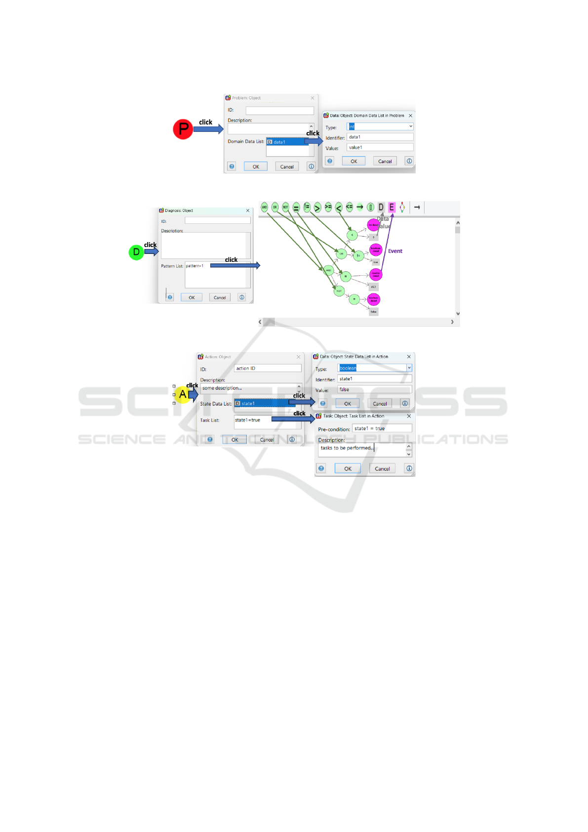
Figure 2: Problem specification in DecSup.
Figure 3: Diagnosis and pattern model specifications in DecSup.
Figure 4: Action specification in DecSup.
(AND, OR, NOT), the relational operator symbols (=,
<, >, ! =, <=, >=), event reference symbol (i.e.,
“E”), and data value symbol (“D”).
3.3 Action Component Type
Whenever any diagnosis pattern predicate evaluates to
true, some action is expected to be operated. An Ac-
tion component type is for specifying the action de-
scriptions, which is composed of one or more state
variables and task elements. A state variable repre-
sents a particular state that the action component can
be in when the associated diagnosis pattern is satis-
fied. Each state variable is specified with a data type
(e.g., int, boolean, and string), identifier and initial
value. A task element represents the task(s) that needs
to be performed assuming that the action component
is in a particular state (i.e., the pre-condition is satis-
fied). A task element is therefore specified with a pre-
condition on the state variables and a task description.
Figure 4 shows DecSup’s graphical notation set
for specifying an action component. An action com-
ponent is specified with a yellow circle (“A”). When-
ever the action component symbol is clicked, a dialog
box opens for specifying (i) the action identifier, (ii)
any description text, (iii) the state list, and (iv) task
list When the state list area is clicked, a new user in-
terface opens for specifying a state variable. When
the task list area is clicked, again a new user interface
opens for specifying a task.
3.4 Problem-to-Diagnosis Connector
Type
Any connector of the problem-to-diagnosis connec-
tor type is used to connect one problem component
MODELSWARD 2024 - 12th International Conference on Model-Based Software and Systems Engineering
92
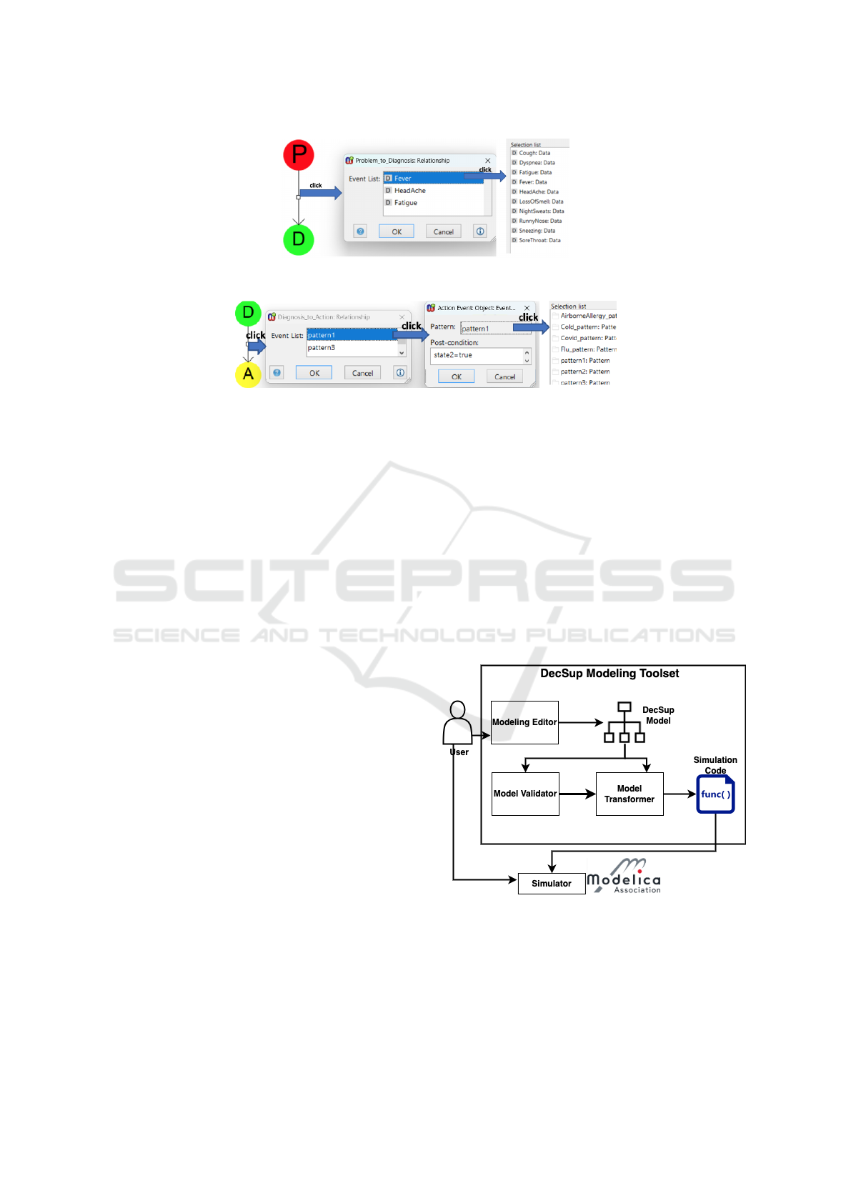
(a) The problem-to-diagnosis connector specification.
(b) The diagnosis-to-action connectors specification.
Figure 5: Specifying connectors in DecSup.
with one diagnosis component so as to specify that
any event occurring due to the problem component is
consumed by the connected diagnosis component. A
problem-to-diagnosis connector is composed of one
or more events. An event here represents the occur-
rence that a domain data variable possessed by the
problem component has got a new value assigned and
thus the diagnosis component can be notified.
Figure 5a shows the directed arrow notation for
the connector, which goes from the problem compo-
nent to the diagnosis component. Whenever the con-
nector arrow is clicked, a dialog box opens for speci-
fying the connector events. Each event is specified by
selecting a problem domain data variable from a list
opening upon clicking the event list area on the dia-
log box. Note that the list opening here consists of the
domain data variables of the problem component that
the connector associates with.
3.5 Diagnosis-to-Action Connector Type
A connector of the diagnosis-to-action connector type
is used to connect one diagnosis component with one
action component so as to specify that any event oc-
curring due to the diagnosis component is going to
be consumed by the connected action component. A
diagnosis-to-action connector is composed of one or
more events. An event here represents the occurrence
that a pattern predicate that is specified as part of the
connected diagnosis component is evaluated to be true
and thus the connected action component can then
be notified accordingly. Each event here is specified
with a reference to an existing diagnosis pattern and
a post-condition statement. The post-condition state-
ment represents the state(s) of the action that need(s)
to be changed (e.g., assigned “true”) upon the occur-
rence of the event (i.e., the pattern satisfaction). By
doing so, the task(s) whose pre-condition on the ac-
tion state are satisfied can get enabled by the action
component due to the occurrance of the event.
Figure 5b shows the directed arrow notation for
the connector, which goes from the diagnosis compo-
nent to the action component. Whenever the connec-
tor arrow is clicked, a dialog box opens for viewing
the event list. If the event-list area is clicked, a new
user interface opens for specifying an event in terms
of its pattern reference and post-condition.
Figure 6: DecSup’s Modeling Toolset Architecture.
4 TOOL SUPPORT
We developed a prototype modeling toolset for Dec-
Sup using the Metaedit+ meta-modeling technology
DecSup: An Architecture Description Language for Specifying and Simulating the Decision Support System Architectures
93

(Kelly et al., 2013)
5
. Figure 6 shows the tool architec-
ture for the DecSup modeling toolset. The modeling
toolset consists of a modeling editor, model validator,
and model transformer. The toolset source files are
available via our research group web-site
6
.
Figure 7 shows the two different modeling editors
supported by the modeling toolset - one for the DSS
architecture modeling (left) and another for the pat-
tern modeling that is accessed through the diagnosis
component as depicted in Figure 3 (right). Each edi-
tor has a (i) toolbar where the graphical symbols can
be dragged and dropped on the modeling area and (ii)
a warning area where the model validation results are
displayed at modeling time. Also, the editor for the
DSS modeling includes a link at the top, which can be
clicked for running the model transformer that trans-
forms the model into the Modelica code.
The model validator here checks any DSS mod-
els for a set of pre-defined properties to ensure that
the models are specified correctly with regard to the
meta-model definitions and completely (i.e., not suf-
fering from any missing information). Some of the
the validation properties that are checked at model-
ing time automatically are (i) any identifiers (e.g., the
identifiers for the components and data variables) or
statements (e.g., task pre-condition and event post-
condition) that are unspecified, (ii) any event that is
used as part of the diagnosis pattern model but has not
been specified as part of the event list of the associated
problem-to-diagnosis connector, (iii) any event that is
created for the event list of a problem-to-diagnosis
connector but has not been associated with any do-
main data of the connected problem component, and
(iv) any event that is used for a diagnosis-to-action
connector but has not been associated with one of the
patterns of the connected diagnosis component.
The model transformer here takes any valid DSS
architecture model and transforms the model into the
simulation code in Modelica. By doing so, the simu-
lators that support Modelica can be used to simulate
the DSS models and execute any test cases. That is,
users can provide some inputs to the simulator and
observe if the simulator that executes the architectural
model produces the correct output or not.
5 CASE STUDY - CONTAGIOUS
RESPIRATORY ILLNESSES
To demonstrate the use of the DecSup language and
its toolset, we considered a case-study from the
5
Metaedit+ web-site: https://metacase.com/
6
Our research group web-site:http://serg.yeditepe.edu.tr
healthcare industry. We used the article published by
National Institutes of Health (NIH) - i.e., part of the
U.S. Department of Health and Human Services - for
the contagious respiratory illnesses (i.e., cold, flu, air-
borne allergy, and Covid-19)
7
. NIH indicates a set of
symptoms from which the cold, flu, airborne allergy,
and Covid-19 diagnoses can be made. NIH also sug-
gests treatments for each diagnosis.
5.1 Architecture Specification in
DecSup
We used DecSup to specify the high-level architecture
of a DSS that can make correct diagnosis of the conta-
gious respiratory illness using the data produced and
offer the correct treatment as described by NIH. The
architecture specification in DecSup is as depicted in
Figure 8. The full specification can be found via our
research group web-site
6
.
Problem Component. To specify the problem com-
ponent, we determined the domain data that are
needed for the diagnosis of the contagious respira-
tory illnesses. As depicted in Figure 8, the prob-
lem component consists of a number of domain data
variables corresponding to the symptoms indicated by
NIH. These are fever, headache, general-aches, fa-
tigue, exhaustion, runny-nose, sneezing, sore-throat,
cough, chest-discomfort, and loss-of-smell-taste.
Diagnosis Components. As depicted in Figure 8,
four diagnosis components are specified - Cold, Flu,
Airborne Allergy, and Covid-19. All those compo-
nents are connected with the same problem compo-
nent via separate connectors. The connector that con-
nects Cold with the problem component includes an
event for each problem domain data - except extreme-
exhaustion. The connector that connects flu with the
problem includes an event for each problem data.
The connector that connects airborne allergy with the
problem includes an event for each problem data -
except fever, general-ache, and extreme-exhaustion.
The connector that connects Covid-19 with the prob-
lem includes an event for each problem domain data.
Each diagnosis component has one pattern model.
In Figure 9, the pattern model specified for the air-
borne allergy diagnosis component is depicted. In
the pattern model, we used a set of events indicated
with the pink ellipse notation and each event corre-
sponds to a unique domain data variable of the prob-
lem component that the diagnosis component is con-
nected in Figure 8. The pattern model here is the log-
ical AND composition of multiple equality operations
7
NIH web-site: https://newsinhealth.nih.gov/2022/01/
it-flu-covid-19-allergies-or-cold
MODELSWARD 2024 - 12th International Conference on Model-Based Software and Systems Engineering
94
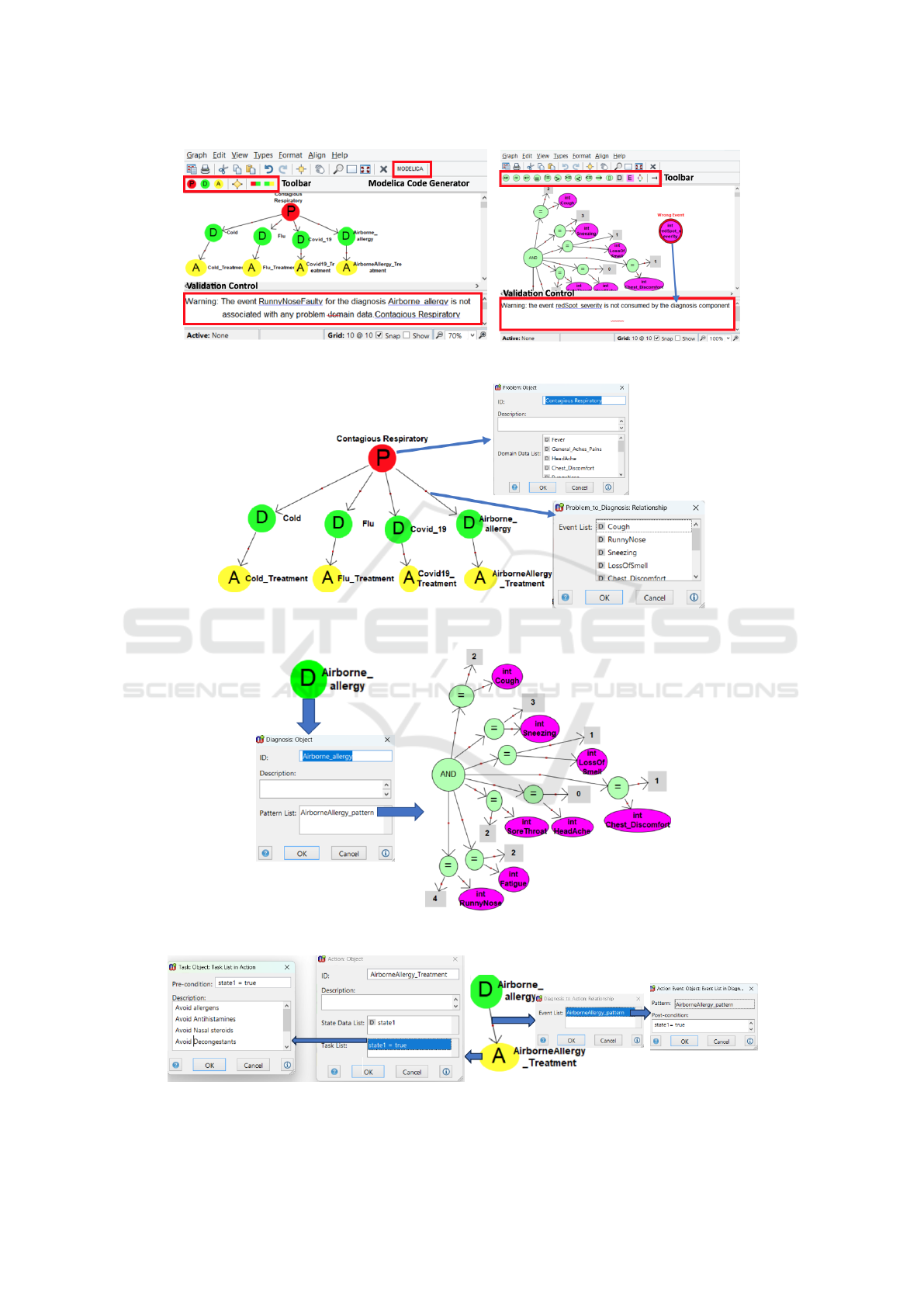
Figure 7: DecSup’s editor support for the model specification, validation, and transformation.
Figure 8: Specifying the DSS architecture for the contagious respiratory illnesses in DecSup.
Figure 9: Specifying the pattern model for the airborne-allergy diagnosis component in DecSup.
Figure 10: Specifying the airborne-allergy action component and its connector in DecSup.
DecSup: An Architecture Description Language for Specifying and Simulating the Decision Support System Architectures
95

each of which checks if the event data is equal to some
value. Note that for simplicity, we consider here the
data “uncommon” described by NIH
7
as the numeric
value “0”, “rare” as “1”, “sometimes” as “2”, “usual”
as “3”, and “common” as “4”.
Action Components. As depicted in Figure 8, each
diagnosis component is connected with one action
component by means of the diagnosis-to-action con-
nectors. Figure 10 shows the connector that connects
the airborne allergy diagnosis component with the
airborne allergy treatment action component. When-
ever the connector herein is clicked, the dialog box
opens for the event specifications. The only connec-
tor event herein is specified with (i) a reference to
the pattern specification given in Figure 9 and (ii) a
post-condition that asserts the state1 state variable of
the airborne allergy treatment action component to
be true. The task specified for the airborne allergy
treatment action here is taken into consideration when
state1 holds true (pre-condition).
5.2 Simulating the DecSup
Specifications Using Modelica
We used the DecSup modeling toolset and trans-
formed the DSS architecture specifications for the
contagious respiratory illness that are discussed in the
previous sub-section in Modelica.
Auto-generated Simulation Code. The transformed
Modelica code includes a separate Model definition
8
(i.e., the basic building block in Modelica) for each
component of the diagnosis and action types. The
model definition for a diagnosis component basically
consists of (i) an input connector statement
8
for each
event specification through which the problem do-
main data are received and (ii) an algorithm section
8
for executing the pattern model specifications of the
diagnosis component. The model definition for an
action component consists of (i) an input connector
statement for each event specification through which
the notifications can be received indicating that the
pattern predicate for that event specification is satis-
fied, (ii) the data variables corresponding to the state
of the action component, and (iii) an algorithm section
for changing the state variables in accordance with the
the post-condition of any event occurring and printing
out the descriptions of the tasks whose pre-conditions
get satisfied upon the state data being changed with
the event post-condition statements. Also, the trans-
formed Modelica code includes another model defi-
nition that represents the entire architecture as speci-
fied in the DecSup model. The model definition this
8
Modelica language user guide: https://specification.
modelica.org/maint/3.6/MLS.html
time includes (i) the instances of the other model def-
initions that correspond to the diagnosis and action
components and their connections with each other as
specified in the DecSup model, and (ii) the connec-
tions of the problem domain data variables with the
diagnosis components. Note that those problem do-
main data variables can be assigned values during the
simulation manually for testing purposes.
Simulation Process with OpenModelica. The trans-
formed Modelica code can be simulated with any
simulators that accept Modelica. We used the
open-source OpenModelica simulator (Fritzson et al.,
2006)
9
as depicted in Figure 11.
Before starting the simulation process, we firstly
determined some test scenarios each of which con-
sists of a concrete problem domain data set (i.e., the
assignment of values to the problem domain data vari-
ables), an expected diagnosis, and an expected treat-
ment. In Figure 11, we considered simulating the de-
sign decisions about the airborne-allergy illness that
are specified and discussed in Section 5.
When we imported the transformed Modelica
code into OpenModelica, the code structure is dis-
played on the simulator (see the red-box “1” in Fig-
ure 11). To start the simulation, we assigned the con-
crete values of the problem domain data variables be-
tween 0-4, where 0 represents “uncommon”, 1 repre-
sents “rare”, 2 represents “sometimes”, and 3 repre-
sents “usual”, 4 represents “common”. As shown in
Figure 11 (see the red-box “2” on the right-most side),
the problem domain data variables appear with a box
next to them through which the values can be entered.
Then, we clicked to run the simulation (see the red-
box “3”) with those concrete data set so as to observe
the diagnosis and the action taking place and compare
those with the expected ones in our scenario.
To better understand the simulation results and
test if the expected action is taken given a particu-
lar set of problem data, the action variables (those
with “ ACTION” postfix) existing in the transformed
Modelica code can be searched using the OpenMod-
elica simulator (see the red-box indicated with “4” in
Figure 11). Whenever any action is activated given
the associated diagnosis is made, the respective ac-
tion variable is assigned with “1”. Also, the trans-
formed Modelica code includes a separate variable
for each state variable specified as part of the action
component and those variables need to be changed as
specified in the post-condition of the events occurring
(see Section 5.1). As observed in Figure 11 (see the
variable window indicated with the red-box “4” on
the right), the action variable for the airborne-allergy
is set as “1” and the state variable of the airborne-
9
OpenModelica web-site: https://openmodelica.org/
MODELSWARD 2024 - 12th International Conference on Model-Based Software and Systems Engineering
96
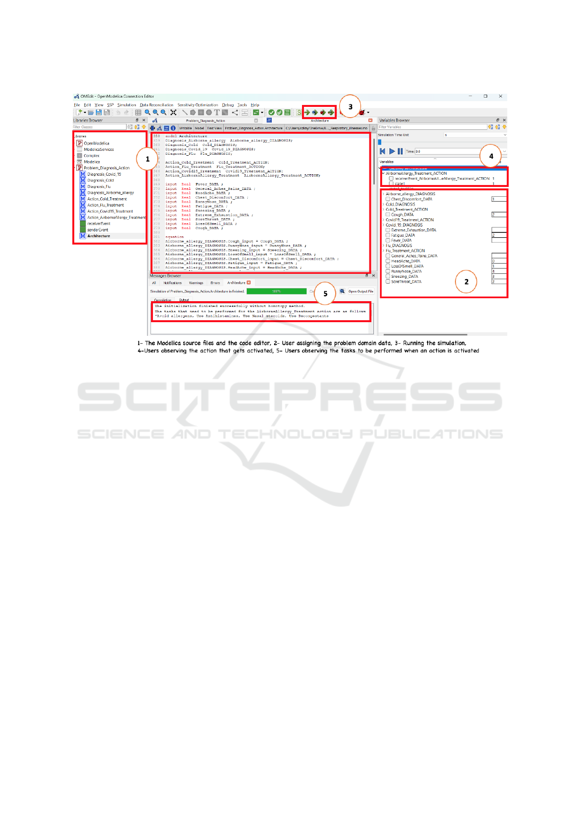
Figure 11: Model simulation using OpenModelica.
allergy action component (i.e., state1) is set as “1”
as the post-condition in Figure 10 asserts so. When
the action state has been changed in accordance with
the post-condition, then the action tasks whose pre-
condition evaluates to true can be performed (see Fig-
ure 10). The descriptions of those activated tasks are
displayed in the message browser part of the simu-
lator user interface (i.e., red-box “5” indicated at the
bottom part in Figure 11).
6 CONCLUSION
In this paper, we introduce a novel architecture de-
scription language called DecSup for the high-level
specifications of DSS architectures and their simula-
tion. DecSup offers a graphical notation set for speci-
fying the DSS architectures in terms of problem, diag-
nosis, and action components that interact with each
other in an event-based manner. Problem components
represent the domain data set about the decision mak-
ing process. The diagnosis components receive event
notifications from the problem component(s) that they
are connected with whenever the problem domain
data that the diagnosis components are interested in
change (or get initialised). Then, the diagnosis com-
ponents process their pattern predicates that are each
specified as a separate model. If the pattern predicate
of a diagnosis component is satisfied, the action com-
ponent that is connected with the diagnosis compo-
nent and interested in the pattern result is notified with
an event. The action component then gets their par-
ticular state(s) changed in accordance with the event
post-condition. Lastly, the action component can op-
erate any of its tasks whose pre-condition on the ac-
tion state get(s) satisfied with the state changes.
DecSup is supported with a prototype modeling
toolset, which consists of a modeling editor, model
validator and model transformation tool. Any Dec-
Sup models specified with the editor can be checked
for some validation properties at modeling time auto-
matically. The valid models can be transformed into
Modelica, which is a modeling language that is sup-
ported by many simulators including the open-source
OpenModelica simulator.
We evaluated DecSup and its toolset using a case-
study that is based on the contagious respiratory ill-
nesses which has been inspired from the article pub-
lished by the National Institutes of Health (NIH).
We used DecSup to (i) specify the DSS architecture
for the contagious respiratory illnesses, (ii) validate
the modeling errors for correctness and completeness,
and (iii) simulate the model using OpenModelica via
some test scenarios and check if the correct diagnosis
is made and the correct actions are taken given some
sample problem data.
In the future, we are planning to evaluate our ap-
proach with a number of case-studies from different
DecSup: An Architecture Description Language for Specifying and Simulating the Decision Support System Architectures
97

problem domains including healthcare, disaster man-
agement, and logistics. We will also extend our mod-
eling toolset with a code generator, which can pro-
duce a decision making software in accordance with
the architectural design decisions specified in DecSup
using the open-source event stream processing frame-
work called Esper
3
.
REFERENCES
Alexander, L. (2002). Decision support systems in the 21st
century. ACM SIGSOFT Softw. Eng. Notes, 27(5):104.
Allen, R. and Garlan, D. (1997). A formal basis for architec-
tural connection. ACM Trans. Softw. Eng. Methodol.,
6(3):213–249.
Almeida, A. C., Bai
˜
ao, F., Lifschitz, S., Schwabe, D., and
Campos, M. L. M. (2021). Tun-o
cm
: A model-driven
approach to support database tuning decision making.
Decis. Support Syst., 145:113538.
Arslan, S., Ozkaya, M., and Kardas, G. (2023). Modeling
languages for internet of things (iot) applications: A
comparative analysis study. Mathematics, 11(5).
Boubeta-Puig, J., Ortiz, G., and Medina-Bulo, I. (2014).
A model-driven approach for facilitating user-friendly
design of complex event patterns. Expert Syst. Appl.,
41(2):445–456.
Charette, R. (2005). Why software fails [software failure].
IEEE Spectrum, 42(9):42–49.
Clements, P. C. (1996). A survey of architecture descrip-
tion languages. In Proceedings of the 8th Interna-
tional Workshop on Software Specification and De-
sign, IWSSD ’96, pages 16–, Washington, DC, USA.
IEEE Computer Society.
Dunkel, J., Fern
´
andez, A., Ortiz, R., and Ossowski, S.
(2011). Event-driven architecture for decision support
in traffic management systems. Expert Syst. Appl.,
38(6):6530–6539.
Feiler, P. H., Lewis, B. A., and Vestal, S. (2006
//aadl.info). The SAE architecture analysis & de-
sign language (AADL): A standard for engineering
performance critical systems. In IEEE Intl Symp. on
Intell. Control, pages 1206–1211.
Fritzson, P., Aronsson, P., Pop, A., Lundvall, H., Nys-
trom, K., Saldamli, L., Broman, D., and Sandholm, A.
(2006). Openmodelica - a free open-source environ-
ment for system modeling, simulation, and teaching.
In 2006 IEEE Conference on Computer Aided Con-
trol System Design, 2006 IEEE International Con-
ference on Control Applications, 2006 IEEE Interna-
tional Symposium on Intelligent Control, pages 1588–
1595.
Fritzson, P. A. (2004). Principles of object-oriented model-
ing and simulation with Modelica 2.1. Wiley.
Garlan, D., Allen, R., and Ockerbloom, J. (1995). Architec-
tural mismatch or why it’s hard to build systems out
of existing parts. In ICSE, pages 179–185.
Garlan, D. and Shaw, M. (1994). An introduction to soft-
ware architecture. Technical report, Pittsburgh, PA,
USA.
Holsapple, C. W. (2008). Decision support systems: Foun-
dations and variations. In Wah, B. W., editor, Wiley
Encyclopedia of Computer Science and Engineering.
John Wiley & Sons, Inc.
Humphrey, W. (2006). Why big software projects fail: The
12 key questions. Software Management, pages 21–
26.
Hussain, A. and Mkpojiogu, E. O. C. (2016). Requirements:
Towards an understanding on why software projects
fail. AIP Conference Proceedings, 1761(1):020046.
Kelly, S., Lyytinen, K., and Rossi, M. (2013). Metaedit+
A fully configurable multi-user and multi-tool CASE
and CAME environment. In Jr., J. A. B., Krogstie,
J., Pastor, O., Pernici, B., Rolland, C., and Sølvberg,
A., editors, Seminal Contributions to Information Sys-
tems Engineering, 25 Years of CAiSE, pages 109–129.
Springer.
Magee, J. and Kramer, J. (1996). Dynamic structure in soft-
ware architectures. In SIGSOFT FSE, pages 3–14.
Medvidovic, N. and Taylor, R. N. (2000). A classification
and comparison framework for software architecture
description languages. IEEE Trans. Software Eng.,
26(1):70–93.
Othman, S. H. and Beydoun, G. (2013). Model-driven dis-
aster management. Inf. Manag., 50(5):218–228.
Ozkaya, M. (2018a). Analysing uml-based software mod-
elling languages. Journal of Aeronautics and Space
Technologies, 11(2):119–134.
Ozkaya, M. (2018b). The analysis of architectural lan-
guages for the needs of practitioners. Softw., Pract.
Exper., 48(5):985–1018.
Ozkaya, M. and Kloukinas, C. (2014). Design-by-
contract for reusable components and realizable ar-
chitectures. In Seinturier, L., de Almeida, E. S.,
and Carlson, J., editors, CBSE’14, Proceedings of
the 17th International ACM SIGSOFT Symposium
on Component-Based Software Engineering (part of
CompArch 2014), Marcq-en-Baroeul, Lille, France,
June 30 - July 4, 2014, pages 129–138. ACM.
Perry, D. E. and Wolf, A. L. (1992). Foundations for the
study of software architecture. ACM SIGSOFT Softw.
Eng. Notes, 17(4):40–52.
Porres, I., Dom
´
ınguez, E., P
´
erez, B., Rodr
´
ıguez,
´
A., and
Zapata, M. A. (2008). A model driven approach to
automate the implementation of clinical guidelines in
decision support systems. In 15th Annual IEEE Inter-
national Conference and Workshop on Engineering of
Computer Based Systems (ECBS 2008), 31 March - 4
April 2008, Belfast, Northern Ireland, pages 210–218.
IEEE Computer Society.
Taylor, R. N., Medvidovic, N., and Dashofy, E. M. (2010).
Software Architecture - Foundations, Theory, and
Practice. Wiley.
Weston, R. H. (2012). Model driven integrated decision-
making in manufacturing enterprises. Adv. Decis. Sci.,
2012:328349:1–328349:29.
MODELSWARD 2024 - 12th International Conference on Model-Based Software and Systems Engineering
98
