
CFD Simulation and Application of Semi-Closed Inclined Simple
Cold Channel in a Data Center Server Room
Kaili Zhao
1
, Dongyang Cai
1
, Yanshan Deng
1
, Rui Bo
1
, Xuening Zhang
1
, Yongmin Cao
1
, Li Wang
2
and Yanpeng Wu
3
1
Tangshan Power Supply Company, Tangshan, China
2
Beijing Siji Zhiyuan Technology Co., Ltd, Beijing, China
3
University of Science and Technology Beijing, Beijing, China
Keywords: Existing Server Room, CFD Simulation, Hot and Cold Mixing, Simple Cold Channel, Semi-Closed Inclined
Simple Cold Channel.
Abstract: An experimental study has been conducted on the simulation and application of semi-closed inclined simple
cold channel in a data center server room. We simulated the airflow condition of each channel inside an
existing server room and the effectiveness of the original semi-closed inclined simple cold channel with the
assistance of Computational fluid dynamics (CFD) simulation,and then analyzed the airflow problem of the
cabinet inlet in the hot and cold mixed flow channel. In this study, high degree of hot and cold airflow mixing,
short circuiting of air in front of cabinets and uneven air conditioning operation load in the server room are
main problems. Three-dimensional numerical simulation technology can not only simulate the expected effect
of the project, but discover potential problems, lay the foundation for later project implementation, and show
the direction for field verification after completion.
1 INTRODUCTION
"Carbon peak" and "carbon neutrality" are hot topics
in today's society, and it is imperative to implement
energy saving and thermal environment optimization
for existing server rooms. In 2011, China's data
centers consumed 70 billion kWh of electricity,
accounting for 1.5% of society's electricity
consumption (Gao C F, 2013). The energy
consumption of the server rooms is proportional to
the operation safety of the IT equipment. High energy
consumption leads to high security, while low energy
consumption leads to reduced security. The
prerequisite for energy saving is to ensure the safety
of the equipment in server rooms. Measuring whether
a data center is energy efficient is actually a measure
of the optimal ratio of energy consumption of each
part under the premise of ensuring the safe and stable
operation of equipment, and ensuring the maximum
energy efficiency ratio of equipment such as servers
and network storage (Qian X D, 2012) As cooling is
responsible for the considerable fraction of the total
facility energy consumption, it is apparent that most
data centers possess ineffective cooling systems and
need effective air and thermal management (Ahmadi
V E, 2020) In order to meet the requirements of the
equipment in the server room for temperature and
humidity, cleanliness, air supply speed and other air
environment parameters, as well as to meet the
requirements of energy saving and consumption
reduction, a reasonable airflow organization is
required to effectively eliminate the heat in the server
room (Liu T T, 2015) In many earlier server rooms,
the arrangement of the internal cabinets is not
completely separated from the cold and hot channels,
and there are cold and hot mixed flow channels (Gao
C F, 2013) The usual approach to optimize the
thermal environment of the server room is to close the
hot and cold channels, (Gao C, 2015) if the average
power of the cabinet in server rooms is not high and
the equipment density is low, then the cost-
effectiveness ratio of the project will be too high,
obviously not worth the loss, and most of the channels
of hot and cold mixed flow are not suitable for closure
in the conventional sense. In view of this
phenomenon, a semi-closed bevel simple cold
channel is created according to local conditions to
separate the cold and hot air flow in the channel as
much as possible, reduce the degree of cold and hot
air mixed flow, eliminate the phenomenon of short
circuit in front of the cabinet, and optimize the
average air inlet temperature of the cabinet. Before
542
Zhao, K., Cai, D., Deng, Y., Bo, R., Zhang, X., Cao, Y., Wang, L. and Wu, Y.
CFD Simulation and Application of Semi-Closed Inclined Simple Cold Channel in a Data Center Server Room.
DOI: 10.5220/0012287300003807
Paper published under CC license (CC BY-NC-ND 4.0)
In Proceedings of the 2nd International Seminar on Artificial Intelligence, Networking and Information Technology (ANIT 2023), pages 542-551
ISBN: 978-989-758-677-4
Proceedings Copyright © 2024 by SCITEPRESS – Science and Technology Publications, Lda.

the implementation of the project, it is necessary to
use CFD simulation software to conduct simulation
tests, to see whether the optimization results meet the
expectations, and to see the impact of the chain
reaction of air flow changes on the thermal
environment of other channels.
2 CFD SOFTWARE
The research on the thermal environment of the
equipment room mainly evaluates the parameters of
the equipment room by establishing mathematical
models, establishing equal scale model tests and
using CFD simulation to simulate and construct the
thermal environment of the equipment room. The
conditions of the model experiment are strict, and the
research process is time-consuming and labor-
intensive. In contrast, CFD simulation modeling is
more efficient and convenient. CFD is an acronym for
Computational Fluid Dynamics. CFD simulation
software is based on the three conservation laws of
fluid flow (conservation of mass, conservation of
momentum and conservation of energy). It is used to
analyze, calculate and predict different physical
quantities (pressure, temperature, speed, etc.) in the
convection field through computer numerical
simulation and graphic images. It is mainly used to
solve various practical problems such as fluid flow,
heat conduction and momentum transfer in
engineering field. Different CFD software, its
functional focus and application areas are different,
can be subdivided into dozens of.
To construct the physical model of the machine
room and simulate the temperature and velocity fields
inside it, it is first necessary to determine the
mathematical model of the machine room, mainly the
control equation model, and the turbulence model.
Control equation modeling describes the basic
physical laws of fluids and macroscopic flow
phenomena. By solving these equations through
numerical methods, the distribution of physical
quantities such as velocity, pressure, and temperature
of the flow field in time and space can be obtained.
The control equation modeling starts with the
assumption that the machine room is well sealed, that
internal and external gases do not communicate
through doors and windows, and that the gas flow in
the machine room must satisfy the law of
conservation of mass, which is:
0
)()()(
z
w
y
v
x
u
t
Where u, v and w are the components of the
velocity vector u on the X, Y, and Z axes, respectively,
in m/s. ρ is the gas density in kg/m
3
, and t is the time
in s. This equation represents the mass conservation
of the fluid in the control volume. That is, the mass of
the inflow control body is equal to the mass of the
outflow control body.
The gas flow in the machine room also needs to
meet the law of conservation of momentum, so the
momentum components of the gas in the machine
room on the X, Y, and Z axes must meet the law of
conservation of momentum, which is:
F
zyxz
p
pwudiv
t
w
F
zyxy
p
pvudiv
t
v
F
zyxx
p
puudiv
t
u
z
zz
yz
xz
y
zyyyxy
x
zx
yx
xx
)(
)(
)(
)(
)(
)(
Where, p is the pressure on the fluid cell body, and
the unit is Pa;
F
n
is the force on the fluid element, the unit is N;
τ
nn
is the viscous stress on the fluid element, the
unit is N/m
2
.
Since the machine room contains heat exchange, it
must also meet the law of conservation of energy,
which is:
T
sgardT
cp
k
divuTdiv
t
T
)()(
)(
This formula can be expanded to:
T
ppp
ssss
s
z
T
c
k
zy
T
c
k
yx
T
c
k
xz
wc
y
vc
x
uc
t
c
)()()()(
where c
p
is the specific heat capacity, the unit is
J/kg•K;
T is the temperature, the unit is K;
k is the fluid heat transfer coefficient;
S
T
is the viscous dissipation term, which is the
fraction of mechanical energy converted to thermal
energy due to viscous action on the gas, the unit is J.
Turbulence modeling refers to the introduction of
additional equations to describe the turbulence effect
of the fluid on the basis of the control equation model,
and the turbulence characteristics of the flow field are
obtained by solving the control equation and the
additional equations through numerical methods.
Because of the slow flow rate of the gas in the
machine room, its pressure change is small, so the gas
density is mainly caused by the temperature change.
Therefore, it is assumed that the gas meets the
Boussinesq assumption, i.e., ignoring the change in
gas density caused by the change in pressure and only
CFD Simulation and Application of Semi-Closed Inclined Simple Cold Channel in a Data Center Server Room
543
considering the change in density caused by the
change in temperature. Given that the gas flow in the
computer room is a large space air flow problem, the
standard k-ε model of turbulence calculation with
high Rayleigh number is used here, and the turbulent
flow viscosity is expressed as a function of the
turbulent pulsation kinetic energy k and the flow
dissipation rate ε. The turbulent flow viscosity is
expressed as a function of the turbulent flow
dissipation rate. The turbulent pulsation kinetic
energy k and flow dissipation rate ε are:
))((
)vu(
2
1
K
222
k
l
k
l
x
u
x
u
u
w
Then the turbulent flow viscosity μ
t
is:
2
t
KC
C
μ
is the empirical coefficient.
In this paper, the simulation operations involved in
testing and practice are all carried out with the help of
a mainstream CFD software - 6SigmaDC, which is
developed by Future Facilities in the UK, and has a
rich and diverse model library, which is easy to build
a data center room, simulate, emulate, and predict the
thermal environment in the data center, and can
display the temperature field, airflow field, pressure
field, humidity, and other environmental conditions in
a variety of ways, such as animation, video, and so on.
3 THE CFD MODELLING AND
SIMULATION OF AN
EXISTING SERVER ROOM
The server room was built and put into use in 2012,
and the IT equipment in the cabinets is old but still
meets the demand. With the adjustment of the
information security policy within the industry, some
functions of the server room were relocated elsewhere,
and some of the equipment in the cabinets are
currently out of service, and the overall load of the
server room has decreased compared to the previous
period.
3.1 Basic Parameters of Server Room
The length of the server room is about 2400mm, the
width is about 1600mm, and the total area is about
384m
2
.
The floor height of the server room is 4500mm, the
walls and columns are covered with color steel plates,
and the internal net height of the server room is
2850mm.
The height of electrostatic movable floor overhead
is 470mm, and the ceiling height of aluminum alloy
microporous square plate is 1180mm.
The air is supplied under the elevated floor, the
grille size is 600*600mm, the opening rate is 50%,
and the natural return air is used.
The server room is equipped with 4 precision air
conditioners with a total nominal cooling capacity of
284kW and a total nominal air volume of 80-640m3/h.
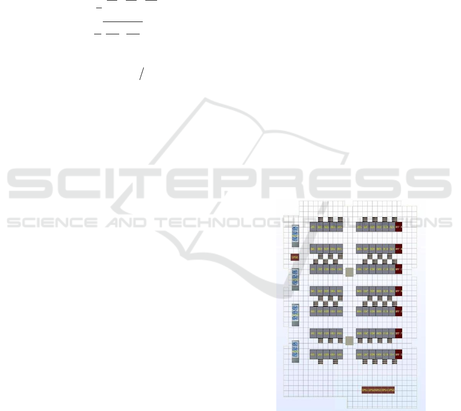
The 77 network cabinets and 7 double-sided
distribution head cabinets in the server room are
distributed in 7 columns (ABCDEFG), each column
consists of 11 network cabinets and 1 double-sided
distribution head cabinet, and the middle of each
column is disconnected by the channel and column,
separated into two groups (5+7). Cold and hot
channels are not closed design, in which the cold
channel of column F and the hot channel of column G
are mixed side by side.
In addition, there are 6 UPS power supply cabinets
in the server room, supplying power to 7 double-sided
power distribution cabinets and 4 precision air
conditioners as well as lighting and security
equipment.
Figure 1: Floor plan of the server room.
3.2 Floor Plan and 3D Model of the
Server Room Constructed by CFD
The floor plan of the server room (Figure 1) and the
3D model of the server room (Figure 2) show the
ANIT 2023 - The International Seminar on Artificial Intelligence, Networking and Information Technology
544
main equipment and facilities such as walls, columns,
network cabinets, power distribution column head
cabinets, precision air conditioners, UPS power
supply cabinets, and delivery grilles.
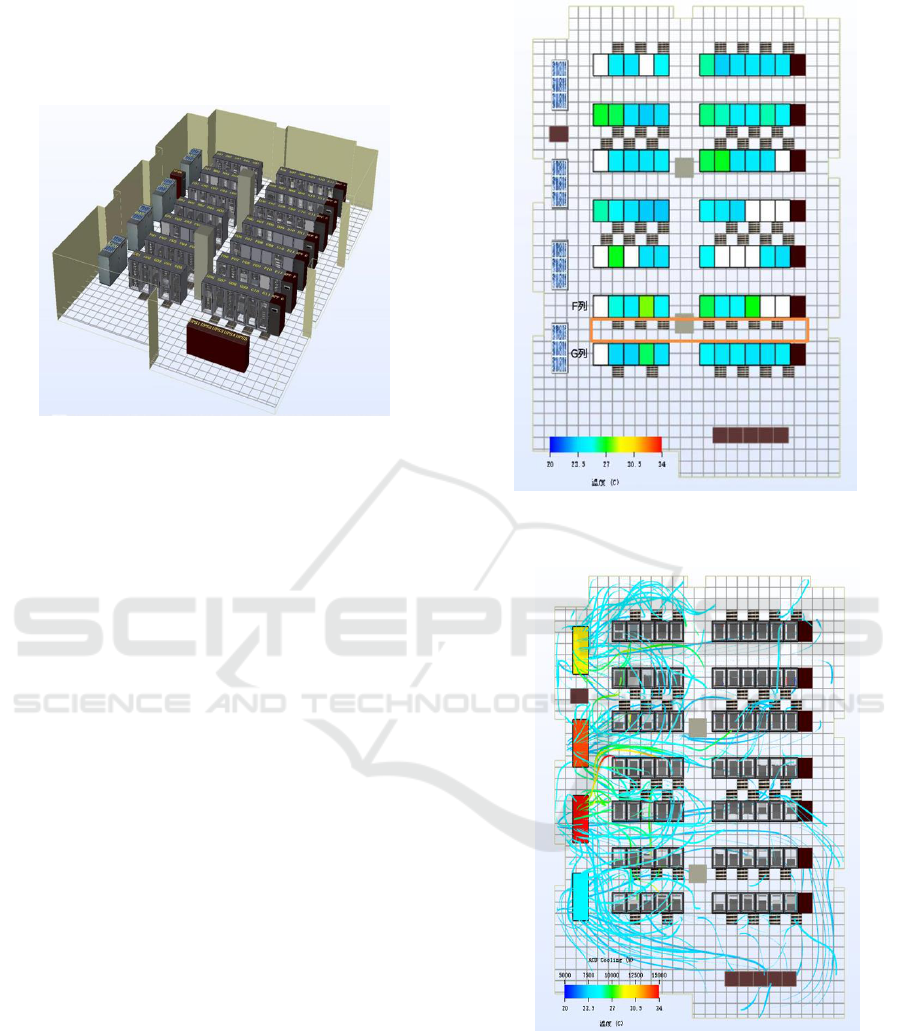
Figure 2: 3D model of the server room.
3.3 CFD Simulation and Analysis of the
Current State of the Thermal
Environment of the Server Room
The four precision air conditioners in the server room
were all in operation, with a total nominal cooling
capacity of 284kW and the air supply temperature set
at 23℃. According to the site statistics, among the 77
network cabinets, except for the wiring equipment
cabinets and the cabinets out of operation, the total
operating power of the remaining 61 cabinets was
about 49.9kW. The hot and cold channels in the server
room were not designed to be closed, and there was a
mixed heat channel between columns F and G. CFD
software was used for 3D modeling of the server
room, and the overall thermal environment status was
obtained by simulation. The average inlet air
temperature of the cabinets (Figure 3) basically
conforms to the safety range of 18℃-27℃ as
stipulated in GB50174-2017 Code for Design of Data
Centers; the maximum sensible cooling power of the
precision air conditioner is 15kW, the minimum
sensible cooling power is 8.484kW, the maximum
return air temperature is 25.2℃, and the minimum
return air temperature is 23℃ (Figure 4); the return
heat index (RHI) of the server room is 0.803, and the
return temperature index (RTI) is 31.5.
The above data reflect the following problems in
the internal airflow organization of the server room:
high degree of mixing of hot and cold airflow inside
the server room; prevalence of air short-circuit in
front of the cabinet; uneven load of precision air
conditioning operation.
Figure 3: Average inlet air temperature distribution of
cabinets in the server room.
Figure 4: The power and flow diagram of precision air
conditioning in the server room.
CFD Simulation and Application of Semi-Closed Inclined Simple Cold Channel in a Data Center Server Room
545
4 CFD SIMULATION AND
ANALYSIS OF A SIMPLE
COLD CHANNEL WITH SEMI-
CLOSED INCLINED SURFACE
The hot and cold channels in the server room were not
closed, and there was a hot and cold mixing channel
between columns F and G. The cold channel of
column F is prepared to be semi-closed in order to
optimize the average air inlet temperature of column
F cabinets. The simulation will be carried out by CFD
software before construction to verify whether the
engineering effect meets the expectation.
4.1 Current Status of Hot and Cold
Mixed Flow Channels
The four cabinets of F column (F03, F04, F08, F09)
and eight cabinets of G column (G02, G03, G04, G05,
G07, G08, G09, G10) were installed with gigabit
enterprise switches and routers. The total power of G
column cabinet is the highest, and the hot channel of
G column and the cold channel of F column are mixed.
CFD simulation results show that the hot air
exhausted from the high-powered equipment in
column G cabinets either enters directly into column
F cabinets to form air recirculation at the top (Figure
5), or mixes into the grille air supply to bring the cold
airflow directly to the top of the channel causing air
short circuit in front of the cabinets (Figure 6), these
phenomena make the average inlet air temperature of
the three cabinets in column F high, exceeding 26°C,
and the interior is prone to invisible hot spots.
The width of the channel between the cabinets in
column G and the cabinets in column F is only
1200mm, it is not possible to carry out a full cold
channel closure in the conventional sense.
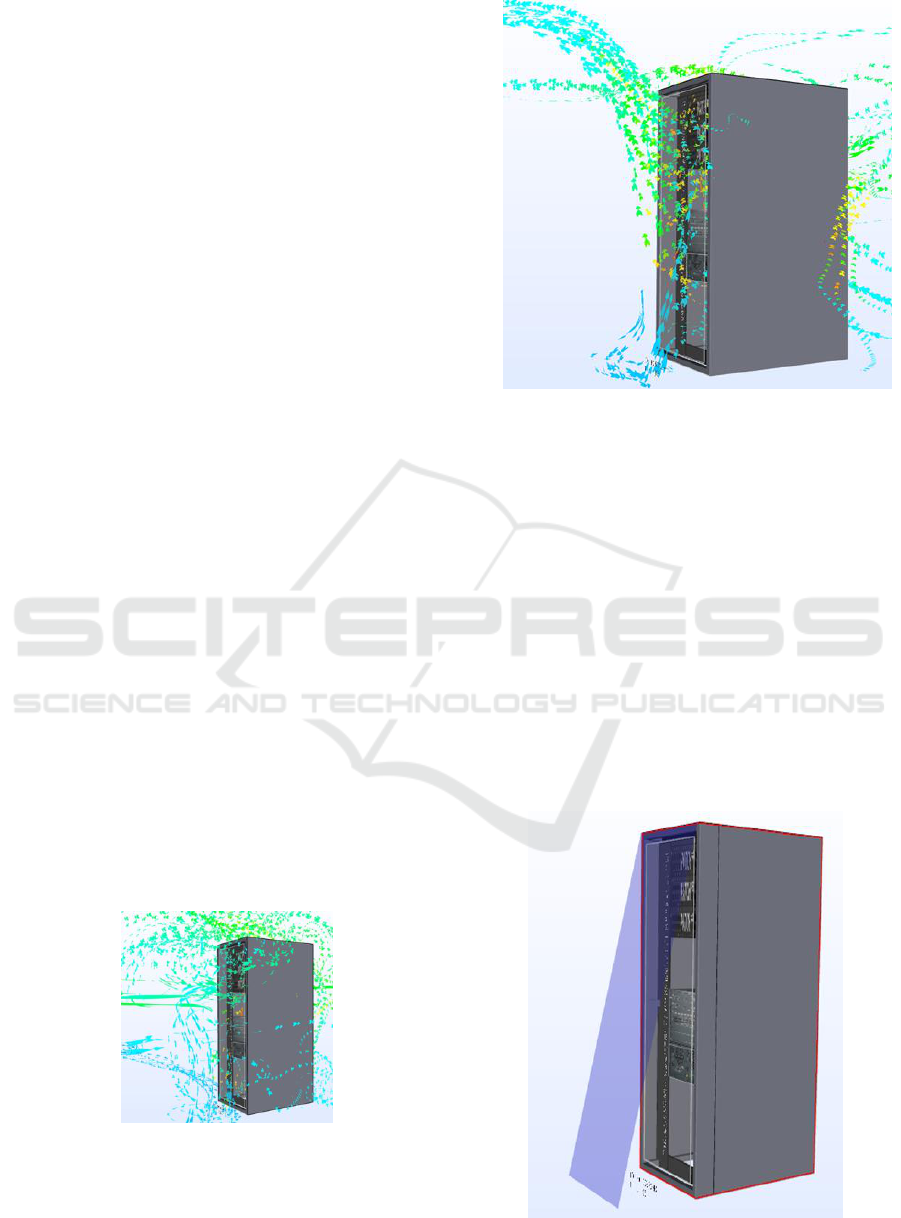
Figure 5: F09 Mixed flow in front of the cabinet and air
recirculation at the top.
Figure 6: Mixed flow and short circuit in front of the F04
cabinet.
4.2 CFD Simulation Results for a
Simple Cold Channel with a Semi-
Closed Inclined Surface in Column
F
In view of the limited space in the channel and the
ease of daily observation and maintenance of the
equipment inside the cabinets, the individual air
curtains in the sloping cold channel take the form of
transparent roller blinds that can be freely retracted
(Figure 7). The cold channel constructed from
continuous air curtains is open on both sides with
triangular sides and a 4mm gap between adjacent air
curtains between cabinets (Figure 8).
Figure 7: Single cabinet air curtain.
ANIT 2023 - The International Seminar on Artificial Intelligence, Networking and Information Technology
546
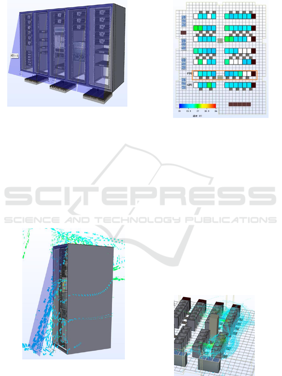
Figure 8: Semi-closed inclined simple cold channel for F
column 01-05 cabinets.
The CFD simulation results show that the semi-
closed inclined simple cold channel can effectively
separate cold and hot air forward. On the one hand,
the hot air discharged from the cabinets in column G
is directed to the top of the channel, and on the other
hand, the cold air sent from the floor grille is
introduced into the cabinets in column F, basically
eliminating the air short circuit in front of the cabinets
in column F and the air recirculation at the top of the
cabinet (Figure 9). The average inlet air temperature
of the cabinets in column F is reduced by 1.6℃ to
below 26℃, and the temperature field is obviously
optimized (Figure 10).
Figure 9: Single cabinet air curtain flow diagram.
Figure 10: Average inlet air temperature distribution of
cabinets after retrofitting.
4.3 Chain Effects and Refinement
Measures for the Establishment of
a Semi-Enclosed Sloping Simple
Cold Aisle in Column F
By comparing the CFD simulation results, we found
that before the renovation, the exhaust air from the
high-powered equipment in column G not only
directly affected the inlet air temperature of column F,
but also indirectly affected the temperature field of
column E (Figure 11). This not only significantly
reduces the chance of mixing hot and cold airflow in
adjacent channels, but also partially improves the
uneven loading of the air conditioners. The apparent
cooling power of the four precision air conditioners
was 12.2kW, 14.3kW, 15kW and 8.484kW before the
retrofit, and 11.8kW, 14.2kW, 14.1kW and 9.808kW
respectively after the retrofit (Figure 13). The heat
return index of the server room was increased from
0.803 before the retrofit to 0.865.
Figure 11: Flow diagram of the G-column cabinets before
the renovation.
CFD Simulation and Application of Semi-Closed Inclined Simple Cold Channel in a Data Center Server Room
547
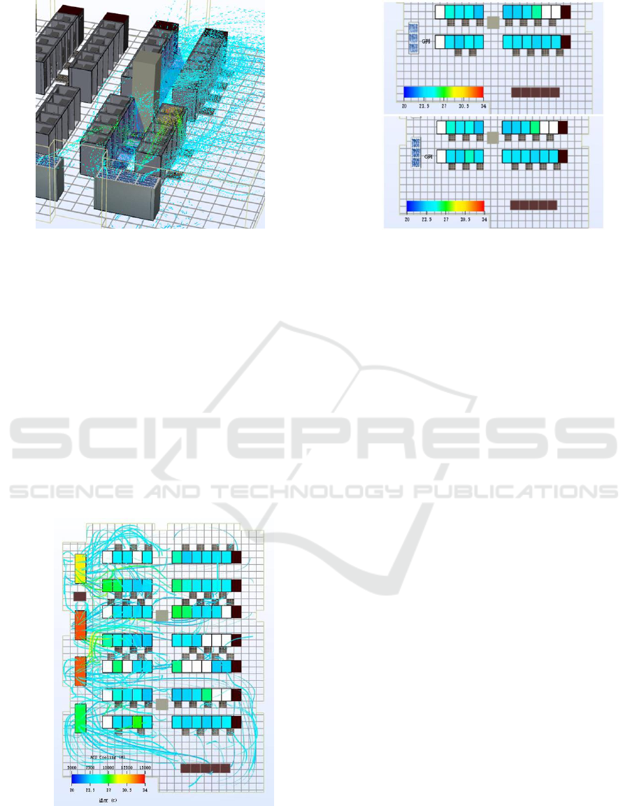
Figure 12: Flow diagram of G-column cabinets after retrofit.
The semi-closed inclined cold channel in column
F separates the hot and cold airflow at the same time,
its wind-blocking effect also affects the exhaust air of
the left inlet and right outlet equipment in individual
cabinets in column G. The simulation results show
that the average inlet air temperature of cabinet G04
has increased by 0.3°C to 26.6°C. In response to this
phenomenon, two optimization solutions are obtained
through CFD software testing, one is to adjust the
position of the air supply grille in front of cabinets 01-
05 in column G, and the other is to add an additional
air supply grille in front of cabinets 01-05 in column
G. Both could reduce the average air inlet temperature
of cabinet G04 by 1.7°C and 1.5°C respectively
(Figure 14), with similar effects.
Figure 13: Sensible cooling power and flow diagram of
precision air conditioners in the renovated server room.
Figure 14: Comparison of average inlet air temperature
distribution after adjusting grilles in column G.
5 PRACTICE AND TESTING OF
A SIMPLE COLD CHANNEL
WITH SEMI-CLOSED
INCLINED SURFACES
After obtaining the simulation results through CFD
software, the field construction was carried out in the
server room, and the field effectiveness of the semi-
enclosed inclined simple cold channel was installed
and monitored.
5.1 Install Air Curtains in Front of Key
Cabinets in Column F
The single wind curtain of the inclined cold channel
is a transparent polyester film (PET film) with a
thickness of 10μm, a width of 780mm and a
maximum length of 2300mm. The rolling curtain
base was made of PVC. The length of the rolling
curtain is 800mm, which is the same as the width of
the cabinet top. The two ends and the middle part are
fixed to the cabinet top. The roller handle is equipped
with a hook, which is easily fixed to the elevated floor
or the air supply grille.
Since the average inlet air temperature of F03, F04,
F08, and F09 cabinets with key equipment in column
F is high, continuous air curtains are first installed in
front of these four cabinets and in front of F02, F05,
F07, and F10 cabinets on both sides (Figure 15 and
Figure 16).
ANIT 2023 - The International Seminar on Artificial Intelligence, Networking and Information Technology
548
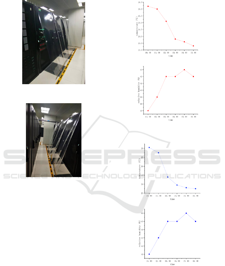
Figure 15: Continuous air curtain in front of the F02-F05
cabinets.
Figure 16: Continuous air curtain in front of the F07-F10
cabinets.
5.2 Monitor the Temperature Change
of Key Cabinets in Column F
Before and After Construction
In order to monitor the temperature changes inside
and outside the cabinets before and after construction,
Bluetooth temperature and humidity monitoring
modules were installed 1m away from the ground at
the door of the F03, F04, F08, and F09 cabinets, at the
upper side air inlet of key devices in cabinets, and at
the lower side air inlet of key devices in cabinets,
respectively, to record the real-time temperature and
humidity changes (Figure 17, Figure 18, Figure 19).
Figure 17: Temperature and humidity change of F09 cabinet
door 1m from ground 3 hours before and after construction.
Figure 18: Temperature and humidity changes in the 3 hours
before and after the side air inlet of the upper part of the
equipment in the F09 cabinet.
CFD Simulation and Application of Semi-Closed Inclined Simple Cold Channel in a Data Center Server Room
549
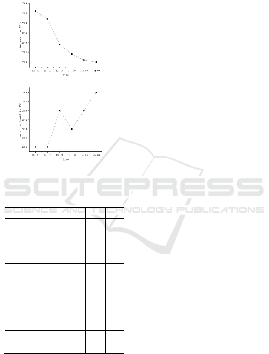
Figure 19: Temperature and humidity changes at the lower
part of the F09 cabinet before and after air inlet construction.
Table 1: Comparison of temperature monitoring results of
F03, F04, F08 and F09 cabinets before and after
construction.
F03
F04
F08
F09
Cabinet door 1m from
ground (average
temperature)
25℃±0.1
24.7℃±0.1
26.8℃±0.1
25.9℃±0.1
(behind the air curtain)
Cabinet door 1m from the
ground (average
temperature)
24.8℃±0.1
24.4℃±0.1
25.8℃±0.1
24.5℃±0.1
Key equipment in the
cabinet upper side air
(average temperature)
27.1℃±0.1
26.4℃±0.1
28.3℃±0.1
27.5℃±0.1
(behind the air curtain)
Upper side air intake of key
equipment in cabinet
(average temperature)
24.7℃±0.1
24.6℃±0.1
25.1℃±0.1
24.8℃±0.1
Key equipment in the
cabinet lower side air intake
(average temperature)
27.4℃±0.1
25.9℃±0.1
28.8℃±0.1
28.4℃±0.1
(behind the air curtain) Key
equipment in the cabinet
lower side air intake
(average temperature)
25.3℃±0.1
25.4℃±0.1
26.5℃±0.1
26.4℃±0.1
By comparing and analyzing the monitored
temperature data, it is found (Table 1) that the average
difference between the temperature 1m from the
ground of cabinets door and the air inlet temperature
of the equipment inside cabinets before construction
was 1.9℃, and the average temperature difference
dropped to 0.4℃ after construction, indicating that
the semi-closed inclined simple cold channel can
effectively import the cold air sent by the grille into
the cabinet. In particular, it has a very obvious effect
on reducing the temperature of the middle and upper
layers of cabinets.
In addition, the return air temperature index RTI
mainly reflects the energy characteristics of the
airflow organization of a certain cabinet, and its
calculation formula is expressed as:
RTI=(T
RETURN
-T
SUPPLY
)/∆T
EQUIPMENT
)×100%
Where T
RETURN
is the return air temperature of the
computer room; T
SUPPLY
is the floor supply air
temperature; and ∆T
EQUIPMENT
is the temperature
difference between the incoming and outgoing air of
the IT equipment in the cabinet.
Before the construction of CFD software
simulation results show that the temperature index of
the return air in the server room is 31.5, after the
installation of the air curtain through the calculation
of the return air temperature index of the eight key
cabinets in column F is 77.4, indicating that the
phenomenon of short-circuiting of air in front of the
cabinets has been significantly reduced.
5.3 Temperature Change of Key
Cabinets in Column G after
Construction
The simulation results of CFD software show that
after the semi-closed inclined simple cold channel
was installed in column F, the air blocking effect will
affect the hot air discharge of individual high-power
cabinets in column G, resulting in an increase in the
average inlet air temperature of the equipment in the
cabinet.
Before construction, a Bluetooth temperature and
humidity monitoring module was installed at 1m from
the ground of the G03, G04, G08, and G09 cabinets
in column G and at the air inlet of the upper side of
key devices in the cabinet to record real-time
temperature and humidity changes. Field monitoring
results show that the eight air curtains in front of the
cabinet in column F have no effect on the temperature
at 1m from the ground of the four cabinet doors in
column G, and the air inlet temperature of the upper
side of the key equipment in the four cabinets is less
than 0.2 ° C, indicating that the establishment of a
ANIT 2023 - The International Seminar on Artificial Intelligence, Networking and Information Technology
550

semi-closed inclined simple cold aisle in column F
will not produce obvious chain effect on the cabinet
in column G, and there is no need to field test the
corresponding alternative optimization scheme.
6 CONCLUSION
In the server room, there are problems such as high
mixing degree of hot and cold air, short circuit of the
air in front of the cabinet, and uneven load of the air
conditioner. Installing a semi-closed inclined simple
cold channel can improve these problems.
(1) In the server room, the hot air from the high-
power devices in cabinets at column G of the
equipment room either enters cabinets at column F
and circulates air at the top of cabinets, or the hot air
is mixed with the grates and carries the cold air
directly to the top of the channel, which shorts the air
in front of cabinets and affects the heat dissipation of
cabinets at column F.
(2) The semi-closed inclined simple cooling channel
directs the hot air from the G-cabinets to the top of
the channel and the cool air from the floor grille to the
inside of the F-cabinets, optimizing the temperature
field of the F-cabinets.
(3) The exhaust air of high-power equipment in
column G cabinets before the transformation also
indirectly affects the temperature field of column E
cabinets. After the inclined cold channel was set up in
column F, the hot air discharged from cabinets in
column G returns to the air conditioner return air
outlet, reducing the mixing probability of hot and cold
air in the adjacent channel and improving the uneven
load of the air conditioner. However, the air blocking
effect also affects the exhaust air of cabinets in
column G. The effect can be eliminated by adjusting
the position of the air supply grille in column G or
adding the air supply grilles.
(4) After experiments, the installation of a semi-
closed inclined simple cold channel in F-column
cabinets can effectively channel the cold air sent by
the grille into cabinets interior, especially for
reducing the temperature of the middle and upper
layers of cabinets interior has a very obvious effect,
and there is no obvious chain effect on the G-column
cabinets.
REFERENCES
Gao C F, Yu Z, Wu J L. Thermal environment analysis and
air distribution optimization for a typical data room (J).
Heating Ventilating & Air Conditioning, 2013, 43(9):
101-106.
Qian X D, Li Z. Energy saving research on air conditioning
system in data centers (J). Heating Ventilating & Air
Conditioning, 2012, 42(3): 91-96.
Ahmadi V E, Erden H S. A parametric CFD study of
computer room air handling bypass in air-cooled data
centers (J/OL). Applied Thermal Engineering, 2020, 166:
114685. DOI:10.1016/j.applthermaleng.2019.114685.
Liu T T. Air distribution simulation and operation
optimization for a data room (J). Heating Ventilating &
Air Conditioning, 2015, 45(3): 71-75.
Gao C, Yu Z, Wu J. Investigation of Airflow Pattern of a
Typical Data Center by CFD Simulation (J/OL). Energy
Procedia, 2015, 78: 2687-2693. DOI:
10.1016/j.egypro.2015.11.350.
CFD Simulation and Application of Semi-Closed Inclined Simple Cold Channel in a Data Center Server Room
551
