
An Interactive Graph Layout Constraint Framework
Jette Petzold
a
, S
¨
oren Domr
¨
os
b
, Connor Sch
¨
onberner
c
and Reinhard von Hanxleden
d
Department of Computer Science, Kiel University, Kiel, Germany
Keywords:
Automatic Graph Layout, User Intentions, Layout Constraints, Layered Layout.
Abstract:
Several solutions exist to constrain nodes or edges for creating desired graph layouts or arrangements via
automatic layout. However, these constraints, which are often handled in separate views, tend to produce con-
flicts if not handled carefully. We present an interactive layout framework that visualizes existing constraints
and available new constraints interactively in the diagram. Adding constraints via diagram interaction allows
reevaluation of existing constraints based on the intended movement of the constrained node and prevents con-
flicts between constraints. The framework can easily be utilized by new layout algorithms and is independent
of the actual layout implementation.
1 INTRODUCTION
Automatic graph drawing is concerned with generat-
ing graph drawings or layouts optimizing a subset of
layout properties. As suggested by (B
¨
ohringer and
Paulisch, 1990), layout constraints are a powerful tool
to tweak graph layouts and to create stable layouts for
automatic layout algorithms, such as the Sugiyama al-
gorithm (Sugiyama et al., 1981), also called the lay-
ered algorithm. They allow users to adjust diagrams
to special use cases that are not supported by gen-
eral layout algorithms and can improve layout stabil-
ity, node grouping, and, in certain cases, even edge
crossings. Layout stability and node grouping are es-
pecially important since they preserve the mental map
(Purchase et al., 2006), while edge crossings is one of
the most important criteria (Purchase, 1997).
Since constraints might be complex or contradict
each other, the user needs to have an intuitive interface
when working with them. The question how auto-
matic layout can be augmented by a constraint frame-
work is separated into four sub-questions:
RQ1: How to visualize possible constraints?
RQ2: How to add constraints?
RQ3: How to address conflicting constraints?
RQ4: How to visualize existing constraints?
a
https://orcid.org/0000-0002-5559-7073
b
https://orcid.org/0000-0002-8011-8484
c
https://orcid.org/0000-0002-9298-6641
d
https://orcid.org/0000-0001-5691-1215
An interactive layout framework, solving these ques-
tions, utilizes an interactive layout overlay or inte-
grates it into the used layout algorithm and resolves
conflicts between constraints, while keeping the lay-
out stable. An integration in a layout algorithm re-
quires changing its implementation, which prevents
the overlay from being applied to other algorithms.
An interactive overlay instead visualizes existing con-
straints and offers manipulation of constraints, while
being independent of the concrete algorithm imple-
mentation. The overlay should only depend on the
output format of the layout algorithm and not its con-
figuration. The overlay informs users about possible
constraints, solving RQ1.
Solution options for RQ2 are adding layout con-
straints textually, provided a textual source exists, or
interactively in the diagram. We focus on diagrams
that are generated automatically based on a textual
source and propose to interact with the diagram. We
use drag-and-drop interaction to add constraints since
it directly corresponds to the semantics of the con-
straint, i. e. moving a node to the desired position. The
interactive addition of constraints allows reevaluation
of existing constraints if they would otherwise contra-
dict each other.
Constraints need to be serialized into the textual
source model to persist them. That is why constraints
can also be added textually which can lead to conflict-
ing constraints. The framework should anticipate this
and be robust even if contradicting constraints are in-
troduced in such a manner. This robustness and the
reevaluation solve RQ3.
240
Petzold, J., Domrös, S., Schönberner, C. and von Hanxleden, R.
An Interactive Graph Layout Constraint Framework.
DOI: 10.5220/0011803000003417
In Proceedings of the 18th International Joint Conference on Computer Vision, Imaging and Computer Graphics Theory and Applications (VISIGRAPP 2023) - Volume 3: IVAPP, pages
240-247
ISBN: 978-989-758-634-7; ISSN: 2184-4321
Copyright
c
2023 by SCITEPRESS – Science and Technology Publications, Lda. Under CC license (CC BY-NC-ND 4.0)

In the following, we introduce our framework as
a showcase how an interactive layout overlay for the
layered algorithm can look like. The focus lies on
how constraints need to be reevaluated preventing
conflicts.
Figure 1 shows the integration into VS Code. On
the left, we see the editor with the textual source
model. On the right we see the interactive diagram
view model with a diagram option side panel, which
can be used to configure the layout or the diagram it-
self. In both models the existing constraints can be
seen (RQ4). In the source model they are determined
with positionChoiceConstraint and layerChoiceCon-
straint and in the view model they are visualized with
icons attached to the nodes.
1.1 Contribution & Outline
Section 2 presents related work. The main contribu-
tions covered in Section 3 are as follows: We present
an interactive layout overlay, show how absolute and
relative constraints for layered layouts can be set, and
present their interaction. Section 4 introduces the im-
plementation of our framework and evaluates the pro-
posed constraint reevaluation steps for the layered al-
gorithm. Finally, Section 5 concludes this paper.
2 RELATED WORK
(B
¨
ohringer and Paulisch, 1990) introduce constraints
for the layered algorithm. The created layouts are sta-
ble and respect semantic constraints that cannot be ex-
pressed as part of the layout algorithm itself. A con-
straint manager allows adding, deleting, and querying
the constraint network of absolute positioning, rela-
tive positioning, and clustering constraints. In con-
trast to our approach, which allows to drag-and-drop
nodes in the diagram itself, the user works with pop-
up menus. The drag-and-drop allows providing an
overlay that illustrates the available constraints and
hence clarifies the consequences of an action.
(Borning et al., 1987) introduce constraint hier-
archies to solve conflicting constraints. The user can
set priorities on constraints and an algorithm is intro-
duced solving conflicting constraints by preferring the
constraint with the highest priority. We, in contrast,
want to prevent the creation of conflicting constraints
instead of solving them afterwards via priorities.
(Waddle, 2001) focuses on constraints for laying
out data structures with a layered algorithm. The de-
cisions the algorithm takes during the layout are ad-
justed such that the introduced constraints are consid-
ered. The contrast to our work is, that we do not mod-
ify the algorithm itself, which allows our framework
to be utilized for several layout algorithms.
(McGuffin and Jurisica, 2009) provide selection
of multiple nodes and radial menus containing actions
to modify the selected elements. This way a range of
actions can be supported. However, we want to follow
a more intuitive approach, where only drag-and-drop
of nodes is used.
Wybrow showcases how constraints are specified
and evaluated using the Dunnart tool (Wybrow, 2008;
Dwyer et al., 2009). The introduced constraints work
on real positions and specify the alignment of nodes
and the direction of edges. We instead focus on se-
mantic constraints dependent on the used layout al-
gorithm. Wybrow visualizes constraints by marking
constrained edges and showing alignment help lines.
This is similar to our approach as shown later.
3 INTERACTIVE LAYOUT FOR
LAYERED LAYOUT
As an example how such an interactive constraint
overlay looks like, we showcase on the example of
the layered algorithm, how absolute and relative con-
straints, as proposed by (B
¨
ohringer and Paulisch,
1990), can be implemented.
The layered layout places nodes in consecutive
layers. E. g., the graph in Figure 1 has three layers
with the nodes AAA, AA, and A in the first one. Natu-
rally, this supports absolute position constraints con-
straining the layer and the position in the layer, pre-
sented in Section 3.1. Relative constraints constrain
the position of a node relative to another node and are
explained in Section 3.2. Section 3.3 presents the in-
teraction between the two constraint types. Adding
constraints (RQ2) is done by moving a node and
releasing it on the desired position in the diagram,
which adds the constraint to the source model. We
provide the user with a diagram overlay for each con-
straint type indicating available constraints (RQ1).
The interactive addition of constraints allow con-
straint reevaluation. If reevaluation is not possible,
the overlay forbids to set the constraints (RQ3).
In the following we assume, without loss of gen-
erality, a left to right layout. Additionally, we have
written the values for the constraints manually into
the shown diagrams if they are important.
3.1 Absolute Constraints
We introduce two absolute constraints: layer con-
straint and position constraint. The layer constraint
determines the layer of a node, where 0 is the first
An Interactive Graph Layout Constraint Framework
241
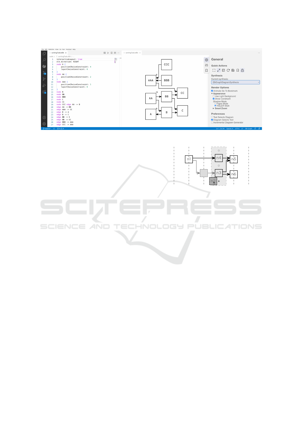
Figure 1: The Visual Studio Code (VS Code) Extension for our interactive layout framework.
layer. The position constraint determines the position
in the layer, where 0 indicates the first position, which
is the top position. When moving a node, the release
position determines the constraint that should be set.
In the following, layer constraints are abbreviated in
figure annotations with LC and position constraints
with PC.
Calculation. Since our framework is independent
of the algorithm and the layer structure as later ex-
plained in Section 4.1, the layer bounds have to be de-
rived from the node positions. The leftmost and right-
most node of a layer determine the horizontal bounds,
while the topmost and bottom-most node determine
the vertical bounds.
A new last layer can be created by releasing the
node to the right of the last layer. A node can also
be released to the left of the first layer. This sets the
desired constraints, but this constraint alone does not
always create a new layer with only the moved node
in it. Nodes that are in the originally first layer, are
not connected to the moved node, and do not have a
layer constraint, will be in the new first layer as well.
This can be prevented if all other nodes, even the pre-
viously unconstrained ones, are constrained to a layer.
Since this is most likely undesired and creates many
potentially unnecessary constraints, we refrain from
doing so.
The new position of the moved node is calculated
by comparing its vertical coordinate with the coordi-
nates of the other nodes in the layer. If the value of
the moved node is lower than all the other, the new
position is 0. Otherwise, it is the position of the node
with the highest coordinate that is lower than the tar-
get coordinate increased by 1.
Each constraint can be set separately. Releasing
the node within its original layer only sets a position
constraint. Releasing the node above or below a layer
Figure 2: Moving n2 activates the interactive layout over-
lay. Layers are shown as lines. A bounding box shows the
current layer and circles the available positions in it.
that is not its original layer only sets a layer constraint.
Both constraints are set when releasing the node in-
side the layer bounds of a layer that is not its original
layer. Releasing the node at its original position sets
no constraint.
Giving a node the same layer constraint as a node
connected by an edge is forbidden, since in-layer
edges are forbidden by the used layered approach. Al-
ternatively, we could allow the movement and delete
the existing layer constraint. However, this could re-
quire deletion of layer constraints of all nodes con-
nected to the first connected node, which compro-
mises layout stability.
User Interface. When moving a node, the incident
edges are not moved, which leads to edges that point
to empty space. That is why we place a shadow of the
moved node at its original position, as seen in Fig-
ure 2. The shadow has the same shape as the original
node but is grayed out. The incident edges are grayed
out as well indicating that they belong to the moved
node.
When moving a node, we visualize the available
layers and the positions in the layer (see Figure 2),
which informs the user about available constraints.
The layer a node is assigned to when releasing is visu-
IVAPP 2023 - 14th International Conference on Information Visualization Theory and Applications
242

alized by a dashed rectangle that surrounds all nodes
in the layer. Dashed vertical lines in the middle of a
layer indicate the other layers a node can be moved
to. The current layer is highlighted in light gray to
prevent confusion if the layer bounds are not visible.
The color changes to gray when the node is moved
above or below the layer and hence only a layer con-
straint is set when releasing the node.
Forbidden layer constraints are visualized by
highlighting the forbidden layer red. Forbidden po-
sition constraints do not exist.
The available positions are visualized by circles,
in the following referred as node slots. The node slots
are placed above the first node, in the middle of two
consecutive nodes, and below the last node, as seen in
Figure 2, excluding the original position of the moved
node. A filled circle indicates that the node would be
assigned to the position the node slot represents. If
only a layer constraint would be set, the node slots
are not shown at all.
Feedback on existing constraints (RQ4) is given
by icons attached to the nodes visualizing the set con-
straints. Nodes with a layer constraint as well as a po-
sition constraint have a lock icon. In the cases where
only one of the constraints is set, the icon is a lock
with an arrow. The arrow is horizontal if the layer
constraint is set, indicating that the horizontal position
of the node is determined by the constraint. Anal-
ogously, a vertical arrow indicates a locked vertical
position and hence a position constraint. The user can
reduce visual clutter by deactivating the icons.
Constraints of a node can be deleted interactively,
by pressing the Alt key and clicking on the node.
Reevaluation. When setting a constraint, updating
already existing constraints might be necessary, e. g.,
when a node is released at position 0, but another node
in the same layer already has a position constraint
with value 0. We call this process reevaluation, which
solves RQ3 and adheres to four principles:
(1) There should be no conflicts between constraints.
(2) No unintended changes in node ordering and edge
routing should occur.
(3) Nodes without constraints do not get constraints,
except the moved node.
(4) Constraints of not moved nodes should only be
changed, if it violates principles (1) or (2).
Principle (1) is the most basic one. If two con-
straints are conflicting, we have to drop one of them
to resolve the conflict. In this process the most recent
action taken by the user has priority.
Principle (2) ensures that the layout remains sta-
ble. If too many nodes or edges move simultaneously
n1
n2
n3
PC 1
PC 0
(a) Initial Graph (b) In Movement
n1
n2
n3
PC 0
PC 1
(c) Result
Figure 3: Releasing n1 in layer 1 on position 0 updates the
position constraints of n2 and n3.
in unpredictable directions, the mental map cannot be
maintained.
Principle (3) ensures that an interaction with the
graph does not introduce unexpected constrains to the
graph. Multiple unnecessary constraints that are not
intended by the user may compromise aesthetic crite-
ria, which compromises the readability of the node-
link diagrams (Purchase, 1997), since they constrain
the graph unnecessarily.
Principle (4) ensures that an interaction does not
delete previous work if this is not necessary, since this
might confuse the user.
The first case where reevaluation is needed is as-
signing a node a new layer and position simultane-
ously (see Figure 3). In the original layer of the
moved node, as well as in the layer the node is moved
to, the position constraints of the other nodes must
be updated. For nodes in the original layer that were
below the moved node, the values of the constraints
must be decremented by 1, as done for node n2 in
Figure 3. Otherwise, the node ordering would have
to change to fulfill the constraints, which would vio-
late our second principle. Nodes without constraints
need no reevaluation. Analogously, nodes in the tar-
get layer that are below the new position of the moved
node are updated. The values of the constraints are
incremented by 1 to keep the node order, as done for
node n3 in Figure 3. This also prevents identical po-
sition constraints for nodes in the same layer.
Another case can be seen in Figure 4, where only
a position constraint is set. There are two cases that
need to be considered: moving a node up and moving
a node down. When moving a node up, the position
constraints of all nodes the moved node passes, are
incremented by 1. For the down case, the constraints
are decremented by 1, as seen in Figure 4c.
When assigning only a layer constraint, only the
original layer of the moved node needs to be reevalu-
ated. The position constraints of all nodes below the
original position of the moved node are decremented
by 1.
If two nodes get the same position or layer con-
straint via textual editing, only the constraint for the
node that is last in the view model is fulfilled. The
An Interactive Graph Layout Constraint Framework
243

n1
n2
PC 1
(a) Initial Graph (b) In Movement
n1
n2
PC 0
(c) Result
Figure 4: Releasing n1 at position 1 updates the position
constraints of n2.
same happens in other cases where constraints that
were added textually contradict each other.
3.2 Relative Constraints
Besides the absolute position constraints, we in-
troduce two relative position constraints as well:
successor-of and predecessor-of. Both constraints de-
termine the position of a node in relation to another
node. When a node has the successor-of constraint, it
is placed below the target node and when a node has
the predecessor-of constraint, it is placed above the
target node in the same layer. Since absolute and rela-
tive constraints overlays partly use the same positions
to highlight available constraints, a second overlay is
required. Holding the Shift key enables the relative
constraint overlay.
Calculation. The node closest to the middle of the
moved node is the target node. Moving the node
above the target node sets a predecessor-of constraint
while moving it below sets a successor-of constraint.
In contrast to the calculation of the absolute con-
straints, the original position of the moved node does
not influence the calculation.
Since connected nodes are not allowed in the same
layer, relative constraints between them are forbid-
den. Releasing a node on a position where a forbidden
constraint would be set sets no constraint. The same
applies when the target of the moved node has a rela-
tive constraint to a connected node of the moved node
or is in another way in relation to a connected node,
which would lead to positioning the moved node in
the same layer.
User Interface. The overlay for interactively set-
ting relative constraints uses blue as the main color
to differentiate it from the overlay for absolute con-
straints.
Moving a node to a position where it would get a
relative constraint highlights the moved node as well
as the target node, as seen in Figure 5. When the
calculated constraint is forbidden, no highlighting is
Figure 5: Releasing n2 above n4 fills the circle over n4 and
highlights n4 and the moved node n2. The interaction re-
sults in a predecessor-of constraint.
n1
n2
n3
(a) Initial Graph (b) In Movement
n1
n2
n3
(c) Result
Figure 6: Releasing n3 inside an existing chain makes n3
part of the relative constraint chain now consisting of n1,
n3, and n2.
done. Additionally, forbidden target nodes are grayed
out when moving a node.
The type of the constraint that will be set is visual-
ized by circles, as seen in Figure 5. If the circle below
the target node is filled, a successor-of constraint will
be set, and when the circle above the target node is
filled, a predecessor-of constraint will be set.
An arrow icon pointing to the target node visual-
izes existing constraints (RQ4), as seen in Figure 6. If
both constraints are set for a node, the arrow points in
both directions.
Deleting a relative constraint is done by pressing
the Alt and the Shift key while clicking on the node.
Reevaluation. The reevaluation adheres to the
same principles introduced for the absolute con-
straints.
If a node is released between two nodes that are
connected with a relative constraint, as seen in Fig-
ure 6, the original constraints that connected the two
nodes are updated to point to the moved node.
Another case is moving a node that is originally
the target of two other nodes. One of them is the suc-
cessor and the other the predecessor. When the moved
node gets a predecessor-of constraint, the constraint
of the original successor is deleted (see Figure 7).
Analogously, if the successor-of constraint is set, the
constraint of the original predecessor is deleted.
Setting a predecessor-of constraint while the tar-
get has a predecessor-of constraint to the moved node
deletes the constraint of the target because the con-
straint that is set the latest has the highest priority.
IVAPP 2023 - 14th International Conference on Information Visualization Theory and Applications
244
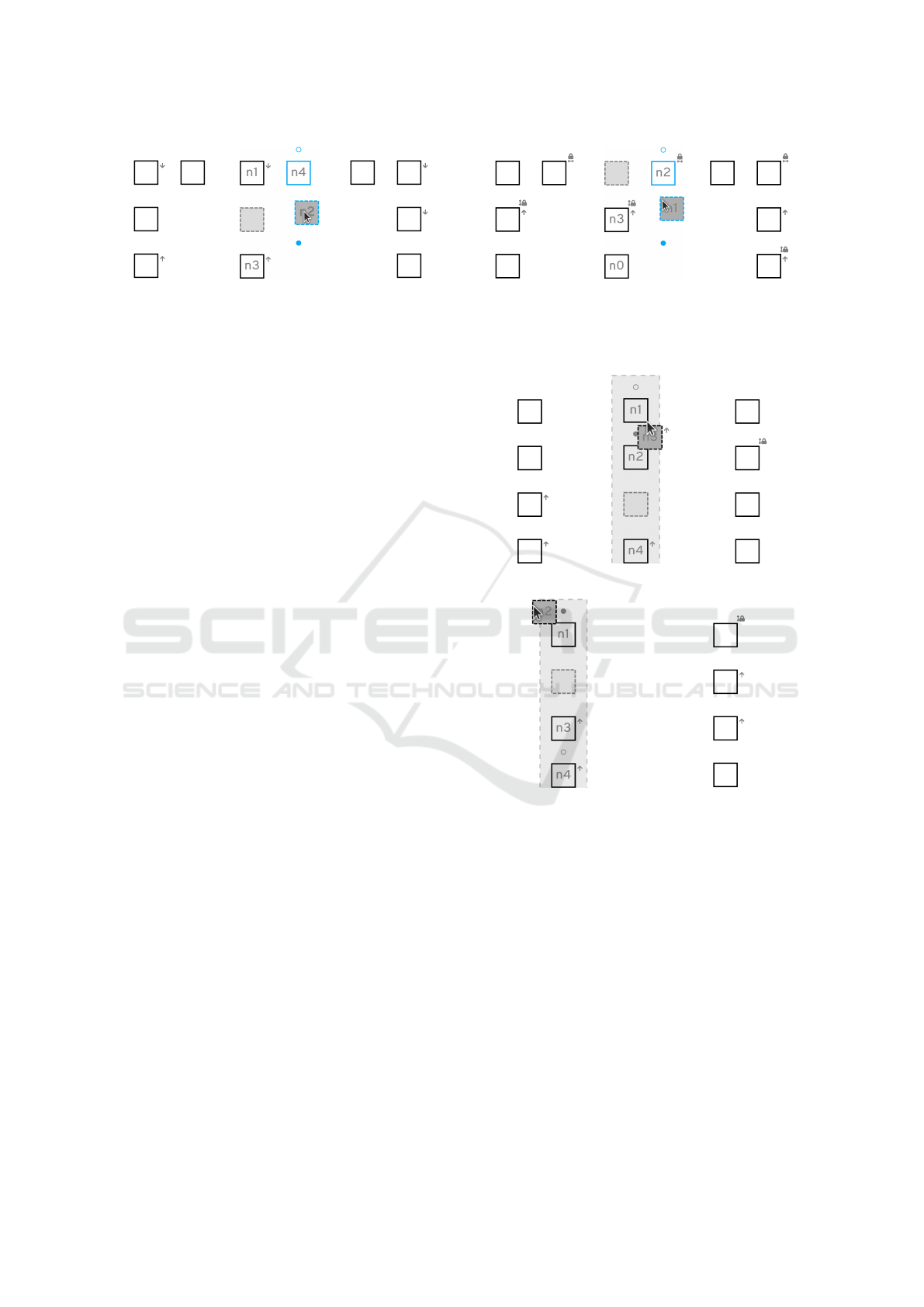
n1
n2
n3
n4
(a) Initial Graph (b) In Movement
n1
n2
n3
n4
(c) Result
Figure 7: Releasing node n2 to succeed n4 deletes the con-
straint of n3 since it is no longer viable.
3.3 Interactions of Absolute and
Relative Constraints
In the following, we present interactions between ab-
solute and relative constraints that need reevaluation.
We will use the term chain for nodes that are con-
nected with each other through relative constraints,
e. g. n1, n2, n3 in Figure 7.
When adding a relative constraint, the moved node
is assigned to the same layer as the target node. This
requires updating the layer constraint of the moved
node. The same applies if the moved node belongs to
a chain containing a node with a layer constraint.
Assigning a node a relative constraint needs
reevaluation of two layers. The position constraints of
nodes in the original layer of the moved node and in
the layer of the target node must be updated similar to
the first reevaluation case of the absolute constraints.
E. g., when the moved and the target node are origi-
nally in different layers, the constraints of all nodes
below the moved node must be decremented by 1 and
the constraints of all nodes below the target node must
be incremented by 1. This way the node orderings of
both layers are preserved.
When a chain containing a node with a position
constraint moves or a node is added, the position con-
straint is reevaluated. If the top node of the chain is
assigned a successor-of constraint, the position con-
straint is adjusted such that the chain moves together
with the moved node, as seen in Figure 8.
If a node is released on the position between two
nodes connected by a relative constraint, the moved
node becomes the new target of the relative constraint
to be consistent to the first case in Section 3.2.
When a node in a chain gets a layer constraint,
the nodes of that chain have to be reevaluated. Since
the user expects to move the whole chain, nodes with
layer constraints in the chain are updated to the new
layer.
When assigning a node that belongs to a chain
only a position constraint, two reevaluation cases
must be considered. If the moved node is in the mid-
n0
n1
n2
n3
PC 1
(a) Initial Graph (b) In Movement
n0
n1
n2
n3
PC 2
(c) Result
Figure 8: Releasing n1 to succeed n2 requires moving
chained nodes with it and updates the position constraints
of the chain.
n1
n2
n3
n4
(a) Initial Graph (b) In Movement
n1
n2
n3
n4
(c) Result
(d) In Movement (Case 2)
n1
n2
n3
n4
(e) Result (Case 2)
Figure 9: Setting position constraints inside a layer with a
relative constraint chain requires constraint reevaluation.
dle of the chain, its relative constraints and the rela-
tive constraints that have the moved node as a target
are deleted, as seen in Figure 9c. In contrast, if the
top node of a chain is moved, the whole chain moves
together with it, as seen in Figure 9e.
3.4 Consider Constraints in Layout
The introduced constraints must be considered by the
layout algorithm. For that the following procedure is
used:
1. Generate an initial stable layout with the layered
layout algorithm.
An Interactive Graph Layout Constraint Framework
245

2. Adjust the coordinates of the nodes based on their
constraints assigning all of them pseudo positions,
which are a representation of the relative positions
between the nodes and not real coordinates that
are assigned by the layout algorithm.
3. Generate the final layout of the graph with the lay-
out algorithm using the pseudo coordinates.
When calculating the pseudo coordinates, all
nodes that should be in the same layer get the same
horizontal coordinate. The coordinate for the first
layer can be set to any value while the value for the
following layers is set such that the coordinate does
not overlap with a node shape of the previous layer.
The vertical pseudo coordinates are based on the or-
dering inside the layer. The top node can be assigned
any value and all other nodes get a value that is greater
than the node that is directly above them.
During the assignment to layers it must be con-
sidered that connected nodes are not allowed to be in
the same layer. One option is to forbid setting a layer
constraint that lead to connected nodes in the same
layer. However, this would heavily limit the con-
straints, since neighboring layers often contain con-
nected nodes and would be forbidden. That is why
we solve the problem by moving connected nodes to
the next layer.
4 VALIDATION
In Section 4.1, we present the implementation of our
interactive layout framework. Section 4.2 presents in-
formal user studies and expert feedback.
4.1 An Interactive Layout Framework
Our interactive framework utilizes Sprotty’s
1
VS Code
diagram view, which we extended to fit our need, and
a language server, which calculates the layout auto-
matically using the Eclipse Layout Kernel (ELK)
2
.
Since this separates layout and visualization into
client and server, the interactive layout overlay must
work independently of the layout. The overlay must
be able to work with the view model and is not able
to access the source model.
If interactive layout is enabled, the user can pick
up nodes and drag them around in the diagram. De-
pending on the used algorithm, an interactive layout
overlay visualizes the available constraints. Releasing
a node on a specific position creates a constraint noti-
fication, which is handled by the language server. The
1
https://github.com/eclipse/sprotty
2
https://www.eclipse.org/elk/
framework supports all languages supported by the
language server, which utilize the same view model.
As also mentioned by (Wybrow, 2008), the con-
straints have to be saved. Since the source model is
the textual model in the editor, serializing the con-
straints is language dependent. This does not only
persist the constraint, but also supports constraint cre-
ation by textual editing and the IDEs reverse action in
the editor to undo the last changes.
4.2 Preliminary User Studies
Discussions with users of the framework revealed that
the interactive layout overlay should show available
constraints and clearly highlight the one that will be
set. Moreover, users want the possibility to only con-
strain the layer or only the position of a node and
not always set both constraints, which can be gener-
alized to all possible constraint types. Disabling the
constraint icons allows to get a normal diagram view,
which is important if the diagram is used for docu-
mentation or papers.
A user study for the layered absolute position con-
straints was conducted with ten computer science stu-
dents with prior knowledge in graph drawing. Before
the experiment started, participants were reminded
about the characteristics of layered graphs.
The first experiment should evaluate and gather
feedback on the basic user interaction. Participants
were given the graph shown in Figure 1 and the task
to move all nodes with the same letter in the same
layer, as it is nearly already done by introducing con-
straints for A, AA, and AAA. As a second task partic-
ipants were asked to sort the nodes in each layer by
the number of letters. All participants reported the in-
teraction with the diagram — our solution for RQ2 —
as intuitive and the circles for the different positions
(RQ1) as helpful. Two participants wanted to have
bigger and flashier node slot indicators.
Two participants reported highlighting the forbid-
den layer in red (RQ3) as helpful, two other par-
ticipants wanted to have more information why this
movement was not allowed. As part of future work it
should be evaluated if hiding forbidden options is the
better alternative, as it is done for relative constraints.
Participants requested new features to create new
layers between existing ones, to the left, or to the right
of the graph, which was partly implemented (RQ2).
Moving nodes to the first or between layers would re-
quire to constrain all nodes after them, which was not
implemented, as already discussed in Section 3.
The limited number of participants and the differ-
ing feedback does not allow inferring definitive solu-
tions and requires further evaluation. However, the
IVAPP 2023 - 14th International Conference on Information Visualization Theory and Applications
246

generally positive feedback indicates the overall ef-
fectiveness of our approach.
The interaction between absolute and relative con-
straints (RQ3) was presented to graph drawing experts
and users of graphical languages supported by the lan-
guage server and reported as intuitive.
5 CONCLUSION AND OUTLOOK
We presented a solution to inform the user about pos-
sible constraints using an interactive constraint over-
lay (RQ1). Adding constraints (RQ2) via simple drag
and drop is intuitive as reported in a preliminary user
study. Possible conflicting constraints (RQ3) are ei-
ther resolved by reevaluating or forbidding the con-
straint, given they are introduced interactively, or by
being robust such that the latest constraint overrides
existing ones. As reported in the preliminary user
study, the constraint icons are sufficient to perceive
existing constraints (RQ4). The framework was tested
by adding interactive layout for tree drawing algo-
rithms, which was able to utilize the already existing
features for the layered approach to change the order
of nodes inside a tree level.
Developer feedback revealed that although the
specification of constraints is intuitive, constraints of
the layout algorithm itself, such as forbidden in-layer
edges of the layered algorithm, might change the lay-
out in an undesired way.
Future work on interactive layout goes in several
directions: (Domr
¨
os and von Hanxleden, 2022) con-
strain the layout via the source model. As part of fu-
ture work it should be evaluated whether users prefer
constraints or textual order to create desired layouts.
Textual order for a stable layout and interactive lay-
out for tweaking the layout of the diagram might be
the ideal solution.
Introducing a new first layer, when using the lay-
ered algorithm, would require to constrain all other
nodes to make this possible. Since this seemed unde-
sired at first glance, this was not added to the frame-
work for the layered approach. Whether it is actually
desired or whether the absence of this option seems
unintuitive should be evaluated as part of future work.
Additionally, other ways to express such a constraint
should be explored.
The movement of a node that belongs to a chain
can be further improved. All nodes that will be
moved together with the moved node, when releasing
it should already move with it to indicate the conse-
quences of the reevaluation.
REFERENCES
B
¨
ohringer, K.-F. and Paulisch, F. N. (1990). Using con-
straints to achieve stability in automatic graph layout
algorithms. In Proceedings of the SIGCHI Conference
on Human Factors in Computing Systems, pages 43–
51, New York. ACM.
Borning, A., Duisberg, R., Freeman-Benson, B., Kramer,
A., and Woolf, M. (1987). Constraint Hierarchies. In
Conference proceedings on Object-oriented program-
ming systems, languages and applications, pages 48–
60.
Domr
¨
os, S. and von Hanxleden, R. (2022). Preserving or-
der during crossing minimization in sugiyama layouts.
In Proceedings of the 14th International Conference
on Information Visualization Theory and Applications
(IVAPP’22), part of the 17th International Joint Con-
ference on Computer Vision, Imaging and Computer
Graphics Theory and Applications (VISIGRAPP’22),
pages 156–163. INSTICC, SciTePress.
Dwyer, T., Marriott, K., and Wybrow, M. (2009). Dun-
nart: A Constraint-Based Network Diagram Author-
ing Tool. In Revised Papers of the 16th Interna-
tional Symposium on Graph Drawing (GD ’08), vol-
ume 5417 of LNCS, pages 420–431. Springer.
McGuffin, M. J. and Jurisica, I. (2009). Interaction Tech-
niques for Selecting and Manipulating Subgraphs in
Network Visualizations. IEEE transactions on visual-
ization and computer graphics, 15(6):937–944.
Purchase, H. C. (1997). Which aesthetic has the greatest
effect on human understanding? In Proceedings of the
5th International Symposium on Graph Drawing (GD
’97), volume 1353 of LNCS, pages 248–261. Springer.
Purchase, H. C., Hoggan, E. E., and G
¨
org, C. (2006). How
Important Is the “Mental Map”? – An Empirical In-
vestigation of a Dynamic Graph Layout Algorithm.
In Proceedings of the 14th International Symposium
on Graph Drawing (GD ’06), volume 4372 of LNCS,
pages 184–195. Springer.
Sugiyama, K., Tagawa, S., and Toda, M. (1981). Methods
for visual understanding of hierarchical system struc-
tures. IEEE Transactions on Systems, Man and Cy-
bernetics, 11(2):109–125.
Waddle, V. (2001). Graph Layout for Displaying Data
Structures. In Proceedings of the 8th International
Symposium on Graph Drawing (GD ’00), volume
1984 of LNCS, pages 98–103. Springer.
Wybrow, M. (2008). Using semi-automatic layout to im-
prove the usability of diagramming software. Dis-
sertation, Clayton School of Information Technology,
Monash University.
An Interactive Graph Layout Constraint Framework
247
