
Biomechanical System Prototype with Advanced Biofeedback for
Rehabilitation of Bedridden Patients
Frederico Santos
1 a
, Luis Roseiro
1 b
, C
ˆ
andida Malc¸a
1,2 c
, Alexandra Andr
´
e
3 d
, Ruben Dur
˜
aes
4 e
,
William Xavier
5 f
, Arm
´
enio Cruz
6 g
and Marco Silva
1 h
1
Polytechnic of Coimbra, ISEC, Rua Pedro Nunes, 3030 -199 Coimbra, Portugal
2
Centre for Rapid and Sustainable Product Development, IPL, Rua de Portugal, 2430-028 Marinha Grande, Portugal
3
Polytechnic of Coimbra, ESTeSC, Rua 5 de Outubro, 3045-043 Coimbra, Portugal
4
ORTHOS XXI, Rua Santa Leoc
´
adia 2735, 4809-012 Guimar
˜
aes, Portugal
5
WISEWARE, Zona Industrial da Mota, Rua 12, Lote 51, Frac¸
˜
ao E, 3830-527 Gafanha da Encarnac¸
˜
ao, Portugal
6
Nursing School of Coimbra, Avenida Bissaya Barreto 143, 3004-011 Coimbra, Portugal
Keywords:
Prolonged Immobility Syndrome, Rehabilitation Therapy Equipment, Lower and Upper Limbs Rehabilitation,
Biomechanical System, Advanced Biofeedback.
Abstract:
Citizens with physical limitations, namely bedridden patients, are often unable to perform physical activity
alone, which can translate into long periods of immobilization, with serious consequences for their health.
This type of patient usually stays in bed for long periods, leading to getting several motor problems due to their
immobility. Thus, it is important to develop biomechanical systems that can be used in the implementation of
physical rehabilitation activities for this type of patient. This work presents a prototype, specifically developed
for bedridden patients, aiming to contribute to the prevention of complications associated with their immobility
for long periods of time. The developed equipment is based on a modular structure allowing a linear module
with active/passive operation and alternatively an active/passive rotary module, to perform different types of
physical movements on upper and lower limbs. This work describes the developed management and control
system with emphasis on the use of biofeedback sensors and real-time data analysis. The first tests carried
out on the prototype clearly identified the benefits of the system when used in physical-motor rehabilitation
procedures for long-term bedridden patients.
1 INTRODUCTION
The World Health Organization has set clear guide-
lines concerning sedentary behaviour, recommending
that all citizens must have regular physical activity.
However, in citizens with physical limitations, partic-
ularly in the case of bedridden patients, the capability
of performing a physical activity is limited, which can
translate into long periods of immobilization, with se-
a
https://orcid.org/0000-0002-4061-9786
b
https://orcid.org/0000-0001-6043-6007
c
https://orcid.org/0000-0003-0012-4380
d
https://orcid.org/0000-0002-9425-6482
e
https://orcid.org/0000-0002-4643-7035
f
https://orcid.org/0000-0002-0864-0809
g
https://orcid.org/0000-0003-3254-3176
h
https://orcid.org/0000-0003-3142-1679
rious consequences for their health. This type of pa-
tient usually stays in bed for long periods, leading to
getting several motor problems due to their immobil-
ity. Reductions in muscle mass, bone mineral density
and physical impairment are the first evidence, asso-
ciated with others that can appear, like muscular at-
rophy, muscular weakness, respiratory complications,
blood circulation complications and bone demineral-
ization (Parry and Puthucheary, 2015), (Parola et al.,
2021) and (Campos et al., 2021).
The absence of muscular stimulation will affect
the skeletal system (Eimori et al., 2016) and early mo-
bilization is a key to increasing functional capacity
and muscle strength in this type of patient, leading
to significant outcomes (Miranda Rocha et al., 2017)
and (Arias-Fern
´
andez et al., 2018). Thus, it is im-
portant to develop biomechanical systems that can be
198
Santos, F., Roseiro, L., Malça, C., André, A., Durães, R., Xavier, W., Cruz, A. and Silva, M.
Biomechanical System Prototype with Advanced Biofeedback for Rehabilitation of Bedridden Patients.
DOI: 10.5220/0011799500003414
In Proceedings of the 16th International Joint Conference on Biomedical Engineering Systems and Technologies (BIOSTEC 2023) - Volume 1: BIODEVICES, pages 198-205
ISBN: 978-989-758-631-6; ISSN: 2184-4305
Copyright
c
2023 by SCITEPRESS – Science and Technology Publications, Lda. Under CC license (CC BY-NC-ND 4.0)

used in the implementation of physical rehabilitation
activities, specifically for this type of patient. To de-
velop and implement correctly this kind of device is
necessary to have a properly defined physical rehabil-
itation program. Several programs have been defined
by some authors, specifically for bedridden patients,
like the works of (Akar et al., 2017) and (Maimaiti
et al., 2019).
According to (Barandas et al., 2015) and (Condino
et al., 2019) the implementation of real-time biofeed-
back systems is important for the effectiveness of
rehabilitation plans, since there are a progressive
growth in people’s motivation and emotional involve-
ment. (Barandas et al., 2015) even mentions that one
of the reasons for the lack of adherence to the pre-
scribed exercise program is precisely the lack of mo-
tivation.
During rehabilitation exercises sessions, it is im-
portant to monitor the patient’s evolution and the pa-
tient’s physical state. To do it, is required to have
one or more equipment capable of monitoring the pa-
tient’s vital signs and the forces that the patient can
produce autonomously. The monitoring of vital signs
can be performed through common medical equip-
ment/devices. However, given the technological evo-
lution, there are already commercialized devices that
allow monitoring some of the most important vital
signs, in a practical and fast way. Moreover, the mea-
surement of forces produced by the patient during the
exercises, allows the clinics to better judge the patient
rehabilitation. In addition, measurement history al-
lows for better evaluation and fine-tuning of rehabil-
itation exercises. Another important aspect of mea-
suring the forces applied/suffered by the patient is the
possibility of automatically adjust the exercises and
limiting the amplitude of movements to the patient’s
condition.
The work presented has its context in the project
ABLEFIT, which aims to contribute to the develop-
ment of methodologies and systems that ensure phys-
ical activity for this type of patient. This project
focuses on the development of physical rehabilita-
tion equipment for bedridden patients, that can con-
tribute to the prevention of complications associated
with their immobility for long periods. The developed
equipment involves a structural support and position-
ing unit, a set of actuators with biofeedback sensors,
and a control, monitoring and gamification unit, with
user interface. In the following chapters, the design
and development of this mechatronic physical reha-
bilitation system and its user interface are addressed.
2 THE ABLEFIT PROJECT
The ABLEFIT project comprises the research and de-
velopment of an advanced physical rehabilitation sys-
tem for bedridden patients with prolonged immobil-
ity, capable of:
• Prevent complications associated with immobility
in bed;
• Increase the functional capacity of the muscu-
loskeletal, cardiac and respiratory systems;
• Promote the integration of physical exercise pro-
grams suited to the clinical condition of each pa-
tient;
• Improve the patient’s quality of life.
The equipment should have an advanced control
system to monitor several parameters related to both
the patient and the performed exercise, especially tak-
ing into account the speed and strength performed by
the patient, or imposed by the equipment. This will
allow to record and evaluate the patient’s progress
and performance. This registration, together with the
implementation of a future gamification solution, are
two extremely important factors when it comes to pa-
tient motivation. Gamification serves as a stimulus
for the user to practice certain exercises. The exis-
tence of a record that allows users to understand their
evolution throughout the rehabilitation period encour-
ages them not to give up on the process, which can
be an important factor in the efficiency/effectiveness
of the exercises. Real-time biofeedback systems are
extremely important for the effectiveness of rehabili-
tation plans, as there is a progressive increase in peo-
ple’s motivation and emotional involvement.
Regarding the physical-motor rehabilitation com-
ponent, the equipment must have the ability to per-
form a set of exercises that guarantee results for pa-
tients. The base system was thus defined for mobi-
lization requirements with flexion, extension, abduc-
tion and adduction of both upper and lower limbs.
2.1 The Prototype
Some of the most common exercise equipment fo-
cuses on one type of movement. This is the case
of stationary bicycles where circular movements are
performed or rowing simulation machines with linear
movements. The prototype concept brings together
both types of movement, and is based on two comple-
mentary modules:
• Linear module for the implementation of linear
movements with a curvilinear trajectory of the up-
per and lower limbs;
Biomechanical System Prototype with Advanced Biofeedback for Rehabilitation of Bedridden Patients
199
• Rotating module for the implementation of circu-
lar movements of the upper and lower limbs.
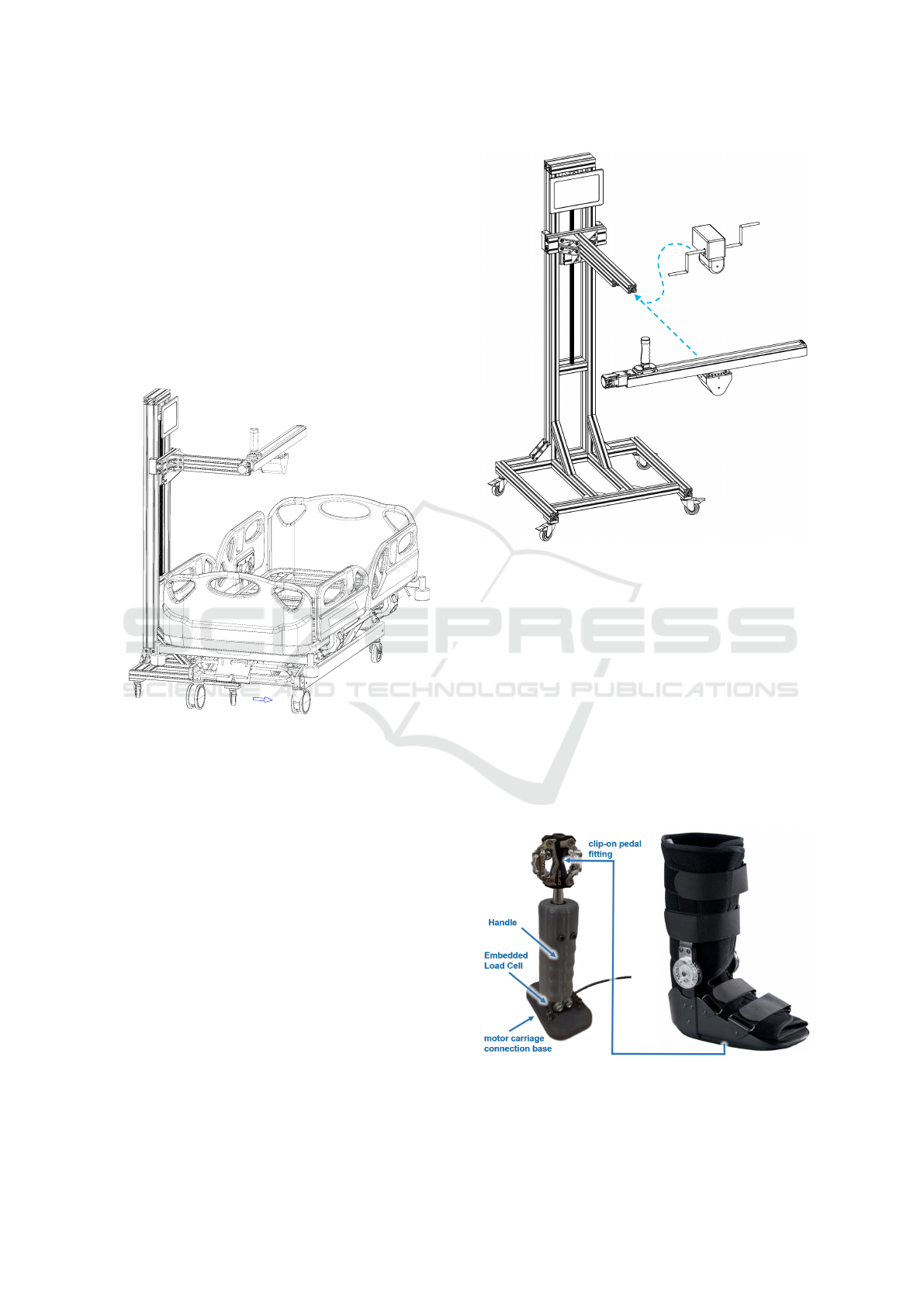
For the intended modularity, a support structure
was developed, with a fitting system for replacing
the modules and vertical tuning, which allows adjust-
ment to the adequate and safe interface with the pa-
tient. The C-shaped system allows adjustment to the
bed where the patient is. Figure 1 shows a view of
the system and its interface that fits to a hospital bed.
The support structure, in addition to guaranteeing the
stability of the modules/interfaces, allows adjustment
and fitting in any bed where a patient lies.
Figure 1: ABLEFIT prototype 3D system visualization next
to an hospital bed.
Figure 2 presents a 3D representation of the sys-
tem with the integrated tablet for visualization / mon-
itorization and the rotary and linear modules, that are
interchangeable, according to the pretended exercises.
This 3D visualization allows an understanding of the
concept developed and presented in the prototype.
2.1.1 Linear Module
The linear module is based on a linear guide unit that
presents a maximum speed of 420 mm/s, a push force
of 400 N and a stroke of 800 mm, which guarantees
the required levels of force, speed and range of mo-
tion for usage in rehabilitation. This linear guide also
includes an absolute encoder enabling a precise and
safe positioning/motion even at startup. This type of
actuator allows its control both in terms of velocity
and position, guaranteeing the implementation of the
system both in an active system line and as a passive
system. The user interface handle is fixed to the slid-
a)
b)
Figure 2: 3D system visualization of the prototype with the
interchangeable rotary and linear components.
ing base of the linear guide. This interface (Figure 3)
includes the motor carriage connection base, a per-
pendicular recessed load cell to the carriage for force
measurement, which allows quantifying the force ap-
plied in both directions of the linear movement, and
an ergonomic external structure for gripping the pa-
tient hand (handle). At the top of the load cell beam,
with a snap-on/disengage system, there is a clip-on
pedal fitting system, which allows the coupling of a
safety hinged boot (walker), thus ensuring the use of
the linear system with the lower limbs, providing leg
support.
Figure 3: Linear module connection to an adapted hinged
walking boot.
BIODEVICES 2023 - 16th International Conference on Biomedical Electronics and Devices
200

2.1.2 Rotary Module
The rotary module involves the use of a DC motor
with reduction gearbox, fixed to a mechanical frame
support connector component, which is attached to
the vertical adjustable, interchangeable end of the
structure. The rotary motor system also guarantees
the use of the system in both an active and passive sys-
tem line, providing enough force and speed. This en-
gine together with the selected gearbox allows a max-
imum speed of 223 rpm, and allows the execution of
a nominal torque of 297.1 Ncm.
The hand handler interface is shown in Figure 4,
and it allows rotation around the shaft. This grip can
be replaced by another one with a pedal strap, as de-
scribed for the linear system, where the boot and strap
are fitted for use with the lower limbs.
Left Embedded
Load Cell
Rotary Motor
Hand Interface
Frame Support Connector
Right Cell Bluetooth
interface
Right Embedded
Load Cell
Left Cell Bluetooth
interface
Figure 4: Rotary module constitution.
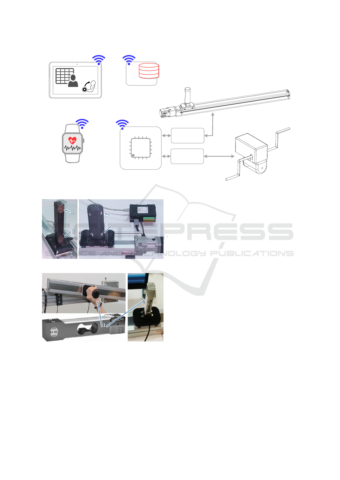
2.2 Management and Control System
Figure 5 presents the complete system, that is com-
posed of:
• Sensors to provide the biofeedback, including
the measurement of the applied forces, velocity
and/or cadence and vital signals;
• Tablet/monitor to be used as interface with the
clinic for parameterization or to be used as gami-
fication visualizer, to encourage the patient;
• The actuators for the linear or rotary movements,
as previously described;
• Database to keep all the patients exercises plans
and relevant data information. The exercises data
include the measured forces, vital signals and du-
ration of exercise, allowing to create automatic re-
ports that can be locally or remotely accessed or
automatically sent to the clinics;
• Microcontroller that acts as the brain of the all the
system, interconnecting all the previous compo-
nents.
This section pretends to better describe each of the
enumerated components. The database is in develop-
ment and will be better explained in future works.
2.2.1 Sensors
To provide a complete biofeedback to the clinics and
to allow the system to better adjust to the limits of the
patient, multiple sensors are required.
The main quantity to measure on rehabilitation
movements is the applied force on the contact point
between the patient and the system. Also, the vital
signs should be evaluated previously, during and by
the end of the exercises.
Sensors on Linear Module
Since the linear module actuator already provides the
position information of the carriage allowing the cal-
culation of the velocity of the movement, the only ex-
tra required quantification is the force applied by the
system to the patient (the system is forcing the move-
ment) or by the patient to the interface (system acts
as load). To measure this force, two distinct versions
were developed:
1. The first experimental sensor setup designed for
this task consisted on a matrix of 4 load cells
(FX29 Compact Compression Load Cell, from TE
Connectivity), shown in Figure 6. The used cells
had a range of 250 N with an amplified output
that can be directly interfaced to the system mi-
crocontroller ADC. This handle configuration ap-
proach enables to measure if the patient is twist-
ing the handle while pooling or pushing it. The
four cells setup could also be used to measure the
handgrip strength with a handle designed for this
effect. This prototype setup, in mechanical terms,
turned out to be complex to adjust and calibrate.
2. The second sensor setup uses only one flexural
load cell, as shown in Figure 7. This sensor is
able to measure only the forces on the direction
of the movement of the linear system, allowing to
evaluate the direction of the applied force. The
used sensor was an AnyLoad load cell, model
108BA, with an analog mV output, that must be
connected to the main microcontroller through a
specific electronic load cell amplifier module. The
main disadvantage of the usage of this cell is the
noise interference susceptibility, that could result
in erroneous measurements.
At the end, the chosen force measurement version
was the flexural load cell, mainly because it allows a
simpler and more robust assembly and fixation. Also,
with this load cell is easier to adapt the clip-on pedal
fitting system to be used with the lower limbs (see
Figure 3).
Biomechanical System Prototype with Advanced Biofeedback for Rehabilitation of Bedridden Patients
201
Linear Motor
Power Driver
USER
DB
DB
Caregiver/User
Graphic Interface
Vital Signals
Motor
Power Driver
Linear Motor System
13 8
14 7
15 6
16 5
1
12
2
11
3
10
4
9
Microcontroller
System
Rotary Motor
System
Figure 5: ABLEFIT Functional Diagram.
Figure 6: Force feedback acquisition with 4 load cells.
Figure 7: Force feedback acquisition with a flexural load
cell.
Sensors on Rotary Module
For rotary movements, its required to quantify the
forces applied on left and right hand/foot interfaces
and the cadence. The characteristic of the movement
on this module, requires the measuring device to be
cable free, i.e., it is impossible to have cables attach-
ing the measuring device to the main microcontroller.
This resulted on the development of a self-powered
device with Bluetooth wireless communication, that
is replicated in each side.
The measure of the force is carried throw an S-
type load cell that is attached to the lateral rotation
shaft, allowing the quantification of the force exerted
by the arm or feet (see Figure 4. This load cell inter-
faces with a low-power microcontroller in a similar
way as described for the flexural load cell applied to
the linear module.
For the cadence quantification, an Inertial Mea-
surement Unit (IMU) can be used, tacking advance of
the embedded gyroscope.
Regarding this device is battery powered, special
attention was carried on power consumption. A low
consumption microcontroller from Nordic Semi-
conductor was chosen, providing a Bluetooth Low
Energy (BLE) interface for the communication with
the main microcontroller.
Sensors for Vital Signals
A survey of all vital signs that would be important
to measure during rehabilitation sessions was carried
out. The vital signs considered to be most relevant and
that can be evaluated using COTS wearable devices
are the following:
• Heart Rate;
• Blood Pressure;
• Peripheral Oxygen Saturation;
• Respiratory Frequency;
• Body Temperature.
BIODEVICES 2023 - 16th International Conference on Biomedical Electronics and Devices
202
A preliminary analysis of available devices, with
open SDK and Bluetooth interface, was already car-
ried and will be integrated in the nearby future.
2.2.2 Actuators
As mentioned before, the described system allows the
patient to make exercises using a linear module for
curvilinear movements and a rotary module for circu-
lar movements, both providing the coupling of upper
or lower limbs. These actuators are exchangeable and
only one is connected at a time.
The chosen linear guide was the EZS6-D080-
AZAKD from OrientalMotor company. This actuator
have a specific controller unit that can be interfaced
with the main microcontroller using ModBus RTU
Protocol. This actuator controller enables to set the
maximum acting force when used in active/passive
modes.
For the rotary movement, a permanent magnet DC
motor with reduction gearbox from Dunkermotoren
company was chosen. The speed and force control for
this motor is carried through a common motor power
driver interfaced with the main microcontroller.
The supply voltage for both actuators is 24V, hell
suited to be directly supplied by a regulated battery
module, allowing safe standalone off-grid operation.
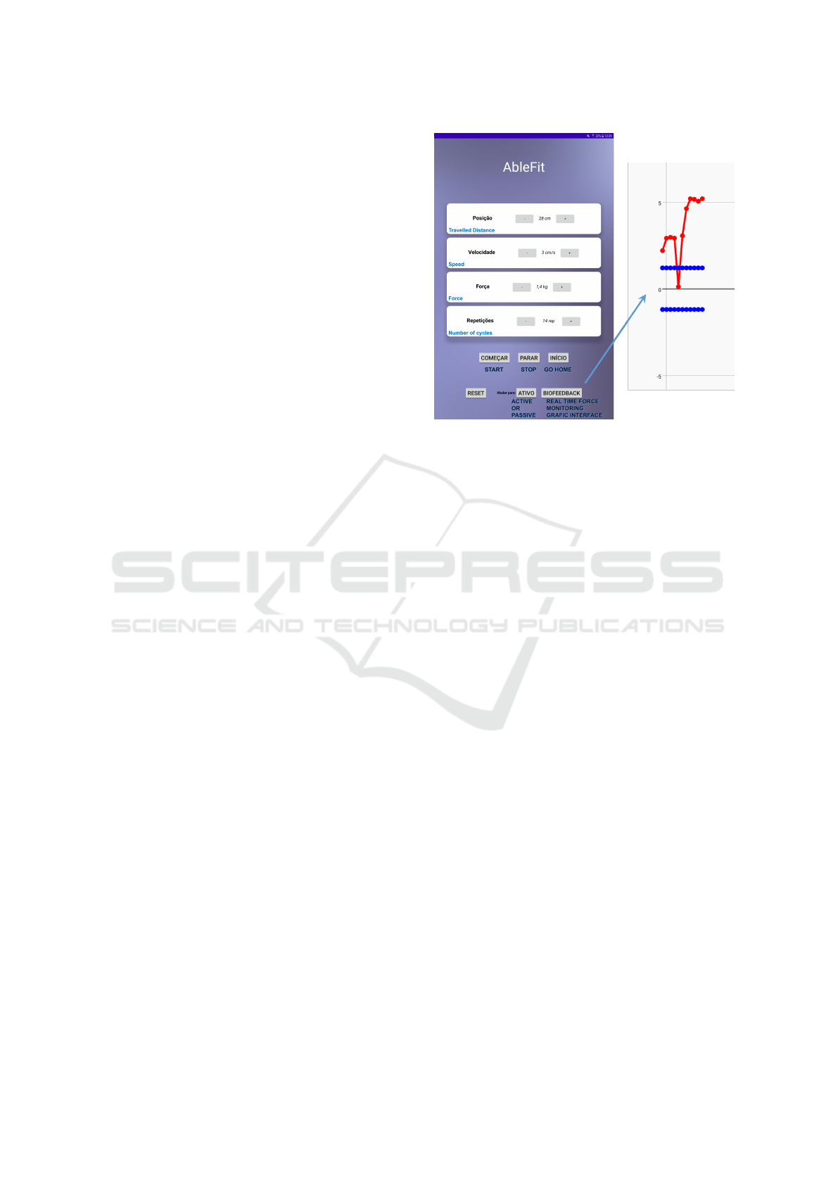
2.2.3 Tablet/Monitor
Fixed to the main structure of the prototype (see Fig-
ure 2) is an Android based tablet used for interaction
with both the patient and the clinic professionals.
For the clinic, the tablet is used to configure all
the system so that it respects the physical limits of
the patient. The developed application has access to
the patient personal data and the respective list of pre-
scribed exercises. It also allows to access the history
of exercises which includes the data from biofeedback
sensors. This feature permits to obtain an historical
assessment of the patient condition over time.
Figure 8 shows a work in progress application.
Left picture is a screen capture of the parameteriza-
tion of the exercise. The right picture shows and real-
time graph of the measured force.
Another usage of the tablet is the gamification and
encouragement of the patient. This feature is under
development at the moment, and the idea is to encour-
age and motivate the patient to realize the exercise.
For example, if the exercise is a rotational movement
with lower limbs, similar to cycling, then the tablet
could show a road with moving scenario to give the
idea of movement. Additionally, to motivate the pa-
tient to apply more force, some virtual cyclists could
Figure 8: ABLEFIT Android APP.
be added, running at the similar speed, so that the pa-
tient try to overtaken them.
2.2.4 Main Microcontroller
The main element of the electronic control system is
the microcontroller, that receives the set-point defini-
tions for the exercise, the information from the all the
sensors, and controls the actuation of the connected
module, either the linear or the rotary actuators.
The microcontroller chosen was an ESP32 that al-
ready integrates a BLE and Wi-Fi interfaces, provid-
ing all the required wired and wireless communica-
tion with the previously present components.
The retrieved information from the attached actua-
tor, is forwarded to the tablet and also internally used
in a classic closed loop fashion control, taking care
that the patient never exceed it’s own physical limita-
tion, as initially configured by the clinic professional,
for the sake of security.
3 EXPERIMENTAL TESTS
The prototype first tests were implemented to identify
possible exercises functionalities, having been carried
out under supervision of health professionals.
Figure 9 shows examples of performing exercises
with the rotary module and Figure 10 shows examples
of performing exercises with the linear module.
The preliminary tests showed that extension and
flexion movements were full performed in active and
passive modes. This special feature allows the proto-
type to be used for rehabilitation of patients that can
Biomechanical System Prototype with Advanced Biofeedback for Rehabilitation of Bedridden Patients
203
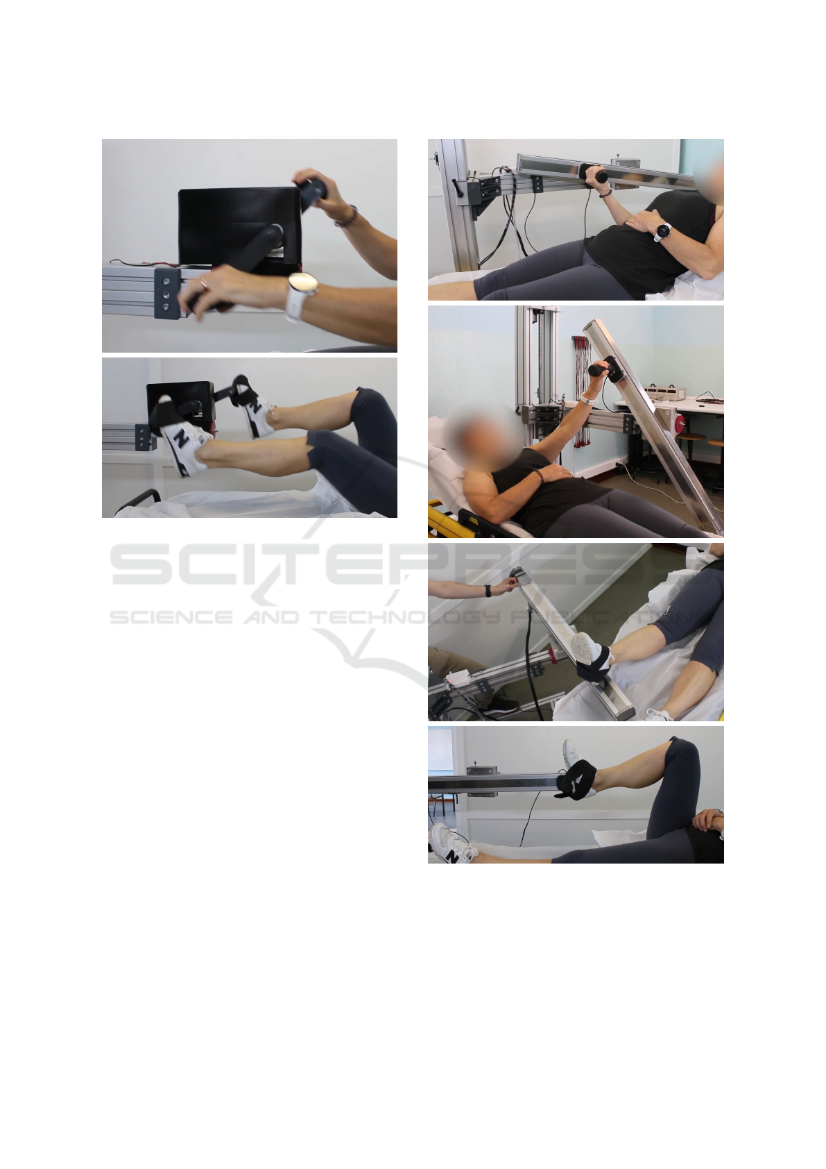
Figure 9: Examples of experimental tests with the rotary
module.
produce movement, and also the rehabilitation of pa-
tients that have loosed all the muscular activity.
4 CONCLUSIONS
This work present the design of a biomechanical pro-
totype equipment for the accomplishment of physical
rehabilitation exercise by bedridden patients. The de-
veloped system allows the realization of a specific set
of exercises, considered relevant for this type of pa-
tient. The system incorporates a linear module and a
rotation module, that are interchangeable. Both mod-
ules can be used in active or passive modes, fully con-
figurable and customized, safeguarding the physical
limitations of the patient.
The developed management and control system
is able to collect information from biofeedback sen-
sors and correctly control the actuators movement ac-
cording to the prescribed exercise. An Android based
tablet is used to motivate the patient through gamifi-
cation, and is also used by the clinic to configure the
exercises, to visualize real-time data or to access his-
torical patient information.
Preliminary tests performed by health profession-
als showed the mechatronics prototype robustness,
evidencing an excellent adjustment and positioning
Figure 10: Examples of experimental tests with the linear
module.
capability, fulfilling the function of interfacing with
the patient in hospital beds, enhancing the realization
of upper and lower limb exercises.
BIODEVICES 2023 - 16th International Conference on Biomedical Electronics and Devices
204

ACKNOWLEDGEMENTS
This research was co-financed by the European Re-
gional Development Fund (ERDF) through the part-
nership agreement Portugal 2020 - Operational Pro-
gramme for Competitiveness and Internationalization
(COMPETE2020) under the project POCI-01-0247-
FEDER-047087 ABLE-FIT: Desenvolvimento de um
Sistema avanc¸ado para Reabilitac¸
˜
ao.
REFERENCES
Akar, O., G
¨
unay, E., Sarinc Ulasli, S., Ulasli, A. M., Kacar,
E., Sariaydin, M., Solak, O., Celik, S., and
¨
Unl
¨
u, M.
(2017). Efficacy of neuromuscular electrical stimula-
tion in patients with copd followed in intensive care
unit. The clinical respiratory journal, 11(6):743–750.
Arias-Fern
´
andez, P., Romero-Martin, M., G
´
omez-Salgado,
J., and Fern
´
andez-Garc
´
ıa, D. (2018). Rehabilitation
and early mobilization in the critical patient: sys-
tematic review. Journal of physical therapy science,
30(9):1193–1201.
Barandas, M., Gamboa, H., and Fonseca, J. M. (2015). A
real time biofeedback system using visual user inter-
face for physical rehabilitation. Procedia manufactur-
ing, 3:823–828.
Campos, A., Cort
´
es, E., Martins, D., Ferre, M., and Con-
treras, A. (2021). Development of a flexible rehabil-
itation system for bedridden patients. Journal of the
Brazilian Society of Mechanical Sciences and Engi-
neering, 43(7).
Condino, S., Turini, G., Viglialoro, R., Gesi, M., and
Ferrari, V. (2019). Wearable augmented reality ap-
plication for shoulder rehabilitation. Electronics,
8(10):1178.
Eimori, K., Endo, N., Uchiyama, S., Takahashi, Y.,
Kawashima, H., and Watanabe, K. (2016). Dis-
rupted bone metabolism in long-term bedridden pa-
tients. PloS one, 11(6).
Maimaiti, P., Sen, L. F., Aisilahong, G., Maimaiti, R., and
Yun, W. Y. (2019). Retracted: Statistical analysis
with kruskal wallis test for patients with joint contrac-
ture. Future generations computer systems: FGCS,
92:419–423.
Miranda Rocha, A. R., Martinez, B. P., Maldaner da Silva,
V. Z., and Forgiarini Junior, L. A. (2017). Early mobi-
lization: Why, what for and how? Medicina intensiva,
41(7):429–436.
Parola, V., Neves, H., Duque, F. M., Bernardes, R. A., Car-
doso, R., Mendes, C. A., Sousa, L. B., Santos-Costa,
P., Malc¸a, C., Dur
˜
aes, R., Parreira, P., Ap
´
ostolo,
J. a., and Cruz, A. (2021). Rehabilitation pro-
grams for bedridden patients with prolonged immo-
bility: A scoping review protocol. International
journal of environmental research and public health,
18(22):12033.
Parry, S. M. and Puthucheary, Z. A. (2015). The impact
of extended bed rest on the musculoskeletal system in
the critical care environment. Extreme physiology &
medicine, 4(1):16.
Biomechanical System Prototype with Advanced Biofeedback for Rehabilitation of Bedridden Patients
205
