
Verifying Static Constraints on Models Using General Formal
Verification Methods
Norbert Somogyi
a
and Gergely Mezei
b
Department of Automation and Applied Informatics, Faculty of Electrical Engineering and Informatics,
Budapest University of Technology and Economics, M
˝
uegyetem rkp. 3., H-1111 Budapest, Hungary
Keywords:
Formal Verification, UML, CTL, Kripke Structure, NuSMV, OCL.
Abstract:
Over the years, the field of software modeling has gained significant popularity. By capturing the static aspects
of the requirements of the software, model-driven engineering easens the development and maintenance of
software. However, additional constraints that the solution must conform to may be too complex to include in
the structure of the model itself. For this reason, external solutions are often used to describe static constraints
on models, the most prevalent approach being the Object Constraint Language (OCL) and its formal variants.
This paper proposes a general approach for verifying static constraints on software models by employing
different formal verification methods than previous solutions. The approach defines a general Kripke Structure
(KS) that captures the static structure of the model. In the next step, the constraints that the model must
conform to are formalized using a first-order branching-time logic, the Computational Tree Logic (CTL).
Finally, the NuSMV model checker tool is used to check whether the constraints formalized in CTL hold on
the formal Kripke Structure. To demonstrate the feasibility of the approach, the concepts are illustrated on a
running UML class diagram.
1 INTRODUCTION
The design and maintainability of complex industrial
software systems is a crucial part of the development
and operations process. Model-driven engineering
aims to alleviate this complexity by defining domain
models that capture the most crucial aspects of the
specification. The most widespread approach to mod-
eling the static structure of the system is OMG’s UML
class diagram (UML, 2017), but different approaches
also exist (MOF, 2005). Further restrictions on the
model are often necessary, namely, those that cannot
(or should not) be expressed in the structure of the
model itself. For example, considering UML class di-
agrams, these could be defining rules for invariants
or adding extra constraints to what constitutes a valid
class diagram. For example:
• The value of a certain attribute of a certain class
must always be above 0.
• Interfaces cannot contain attributes.
• Attributes of primitive type cannot hold further at-
tributes. In fact, only classes are allowed to hold
attributes.
a
https://orcid.org/0000-0001-6908-7907
b
https://orcid.org/0000-0001-9464-7128
• Inheritance hierarchies must not contain cycles
and multiple inheritance is not allowed.
In this paper, we refer to such restrictions as
static constraints. One of the most prevalent solu-
tions for defining static constraints on software mod-
els is the Object Constraint Language (OCL) (Cabot
and Gogolla, 2012) and its variants. OCL is an
OMG specification for a (mostly) declarative, side-
effect free language to define additional restrictions
on UML class diagrams. Although OCL was de-
signed specifically with UML class diagrams in mind,
it is general enough to apply to any modeling lan-
guage, with slight modifications and tailoring to the
modeling notations.
Formal approaches inspired by OCL also
emerged. The most widespread and successful of
these is Alloy (Jackson, 2012), which provides a sim-
ple language for modeling a system and expressing
its properties. In the background, Alloy converts the
model and its properties to a boolean representation
and uses SAT solvers (S
¨
orensson and Een, 2005; Ma-
hajan et al., 2004) to check whether the defined model
conforms to the defined properties. In this paper, we
propose an alternative, general approach for defining
static constraints on software models. The proposed
approach uses different formal verification methods,
Somogyi, N. and Mezei, G.
Verifying Static Constraints on Models Using General Formal Verification Methods.
DOI: 10.5220/0011796500003402
In Proceedings of the 11th International Conference on Model-Based Software and Systems Engineering (MODELSWARD 2023), pages 85-93
ISBN: 978-989-758-633-0; ISSN: 2184-4348
Copyright
c
2023 by SCITEPRESS – Science and Technology Publications, Lda. Under CC license (CC BY-NC-ND 4.0)
85

specifically model checking, to verify whether the
static constraints hold on the software model. In the
first step, the structure of the model is expressed
by a Kripke Structure. The static constraints that
the model must adhere to are then formalized using
the Computational Tree Logic (CTL). Finally, the
NuSMV (Cimatti et al., 2002a; Cimatti et al., 2002b)
model checker tool is reused to check whether the
formalized requirements hold on the formal model.
The approach becomes fully automatic after defining
the mapping from the original model to the Kripke
Structure. The advantage of using formal methods
is that any and all violations are guaranteed to be
found. Thus, formal proof is provided that the static
constraints hold on the model.
The paper is structured as follows. In Section 2,
we present related work and compare them with our
approach. In Section 3, we describe the relevant
theoretical background of model checking, includ-
ing Kripke Structures and CTL. In Section 4, we
present the contribution of this paper. We also illus-
trate the proposed approach on a running example.
Finally, Section 5 concludes the paper, highlighting
main strengths and weaknesses of the approach and
discussing future work.
2 RELATED WORK
One of the most widespread solutions for enforc-
ing static constraints on models is OCL (Cabot and
Gogolla, 2012). OCL supports the expression of
many features, such as invariants, initialization ex-
pressions, or derived elements. It also features its own
typesystem. In their work, Cabot et al. (Cabot et al.,
2021) performed a SWOT ( Strengths-Weaknesses-
Opportunities-Threats) analysis on OCL. The authors
argue that the two main weaknesses of OCL are the
complexity of the language, and the lack of tool
ecosystem and reusable OCL libraries. As a conse-
quence, if a custom modeling language (for which an
OCL implementation does not already exist) intends
to use OCL, implementing an OCL interpreter is a
troublesome, relatively difficult process (Vaziri and
Jackson, 2003).
In contrast, formal verification approaches have
a well-developed ecosystem of tools and methods
available and a well-defined focus for verifying con-
straints. Over the years, a number of such approaches
also emerged. HOL-OCL (Brucker and Wolff, 2008)
intends to define formal semantics for OCL by ”shal-
low embedding of OCL into the Higher-order Logic
(HOL) instance of the interactive theorem prover Is-
abelle.” This approach is designed specifically with
UML in mind, and does not (explicitly) support
other types of models. In their work, Nobakht et
al. (Nobakht and Truscan, 2013) extend static UML
+ OCL models with dynamic verification. By trans-
forming static and dynamic aspects (class diagrams
and statecharts), the whole UML specification is
adapted into the UPPAAL model checker (Behrmann
et al., 2004).
Other approaches focus on checking pre-defined
properties on UML class diagrams. The goal in these
cases is not to replace OCL for defining and checking
constraints on instances of models, but to verify static
properties on the existing UML + OCL model, includ-
ing consistency, executability, reachability, liveness
and satisfiability. UMLtoCSP (Cabot et al., 2007) ap-
plies constraint programming to check the satisfiabil-
ity of OCL constraints on a UML class diagram. Sim-
ilarly, (Shaikh et al., 2010) focuses on improving the
performance of OCL satisfiability checking. In their
work, Przigoda et al. (Przigoda et al., 2016) propose
a formal approach for verifying the structure and be-
havior in UML/OCL models. The possible states of
the system, along with the OCL invariants are trans-
lated into a symbolic representation and SAT solvers
are used to execute verification.
Alloy (Jackson, 2012) is one of the most success-
ful of formal verification-based approaches. Alloy
was inspired by the weaknesses of OCL. It is impor-
tant to emphasize that Alloy is a general approach,
not limited to UML or OCL. It is usable to define any
static constraint on any model. It provides a language
for defining models and uses SAT solvers to formal-
ize and check properties on the model. Similarly to
OCL, it provides its own typesystem, which is more
compact and easier to use. UML2Alloy (Anastasakis
et al., 2007) defines a transformation from UML class
diagrams extended with OCL expressions to Alloy
models. The goal of this approach is to reuse the for-
mal aspects of Alloy to analyse UML specifications.
The authors also note that defining the transformation
from UML class to Alloy was ”challenging”.
When compared to non-formal OCL variants, our
approach has several advantages:
• It uses formal verification methodologies and
tools that are well developed and widespread, pro-
viding automatic, formal proof of the correctness
of the model.
• Our approach is fully independent of the modeling
language that is being checked, making it easier to
integrate with custom modeling languages.
• Our approach focuses specifically on checking
static constraints only. On one hand, it becomes
easier to be used for this purpose. On the other
hand, its expressive power is significantly less
MODELSWARD 2023 - 11th International Conference on Model-Based Software and Systems Engineering
86

than that of OCL. Our approach cannot express
other features of OCL, such as querying models.
Compared to formal approaches, previous solu-
tions focus mainly on extending UML + OCL with
formal semantics or checking the satisfiability or con-
sistency of the models. Against these approaches, the
generality of our approach is the main benefit.
When compared to Alloy, our approach works on
similar grounds but with different formal methods.
Moreover, it is more general, in the sense that it does
not depend tightly on the NuSMV tool. This means
that instead of using NuSMV and the various for-
mal methods it employs (SAT solvers, bounded model
checking etc.), it is possible to use an entirely differ-
ent model checker. In this sense, our approach is easy
to extend with different model checking techniques. It
would also be possible to support different tools, and
let the model designer choose between them. This
is not the case for Alloy, it is built specifically with
SAT solvers in mind. The only requirement in our
case is that the Joint Relational Model (Section 4.3)
should be expressed in the modeling language of the
model checker and a query language similar to CTL
has to be available to formulate the constraints. For
example, a viable alternative to NuSMV would be
Uppaal (Behrmann et al., 2004), with its modeling
language of extended timed automata and a query lan-
guage similar to CTL.
3 BACKGROUND
Formal verification is a group of methodologies
aimed at formally proving the correctness of a spec-
ified system. In our work, we propose to use model
checking to enforce constraints on models. One of the
most typically used and simplest formal models is the
Kripke Structure (Muller-olm et al., 1999) and one
of the most common and practical ways of formal-
izing requirements is the Computational Tree Logic
(CTL)(Muller-olm et al., 1999).
A Kripke Structure is a 4-tuple (S, I, R, L) over
a set of atomic propositions AP, where:
– AP = {P
1
, P
2
, ..., P
n
} set of atomic propositions
– S = {S
1
, S
2
, ..., S
k
} finite set of states
– I ⊆ S set of initial states
– R ⊆ S × S transition relation between states
– L : S 7→ 2
AP
labeling of states with atomic propo-
sitions
Figure 1 illustrates a KS in a graphical represen-
tation. The model consists of 3 states: S
1
, S
2
and S
3
.
The initial state is S
1
, denoted by a double circle. S
1
is labeled with the atomic propositions P and Q, S
2
is labeled with P, and S
3
is labeled with Q and R. Fi-
nally, there exists a transition relation from S
1
to S
2
and S
3
, from S
2
to S
3
and from S
3
to S
1
. A path in a
KS is a possible series of states along transitions. For
example, in this case S
1
→ S
2
→ S
3
→ S
1
→ S
3
is a
possible path.
Figure 1: Graphical representation of a Kripke Structure
with 3 states and 4 transitions.
In CTL, requirements can be formalized using
logical formulae, all of which are presented in Ta-
ble 1. A CTL expression is always evaluated on a
specific state, beginning with the initial state.
Consider now the Kripke Structure depicted in
Figure 1 and the following CTL formula.
AG((Q ∧ P)) =⇒ ((EX¬Q)∨ (EF(P ∧ R))) (1)
The formula prescribes that on all states of all
paths in the Kripke Structure, if a state is labeled with
both Q and P, then there must exist a next state that
is not labeled with Q or there must exist a path on
which eventually a state is labeled with both P and R.
When evaluated over the example, this formula holds,
because S
1
is the only state for which the left side of
the implication holds, and the right side holds as well
because S
2
is a potential next state and it is not labeled
with Q.
4 FORMAL VERIFICATION OF
STATIC CONSTRAINTS
We propose the following approach for checking
static constraints on software models. Figure 2 shows
the steps of the process. Firstly, based on the software
model to be verified, a Joint Relational Model (JRM)
is created. This is a Kripke Structure that models the
structure of the original model to be checked, in the
form of relations between basic model elements. Sec-
ondly, the constraints that the model must conform
to have to be formalized using CTL. The JRM and
the CTL formulae are then forwarded as input to the
NuSMV model checker tool, which verifies whether
the formalized requirements hold on the JRM, and
consequently, on the original model itself. For each
violated CTL formula, a counter example is gener-
ated.
Verifying Static Constraints on Models Using General Formal Verification Methods
87
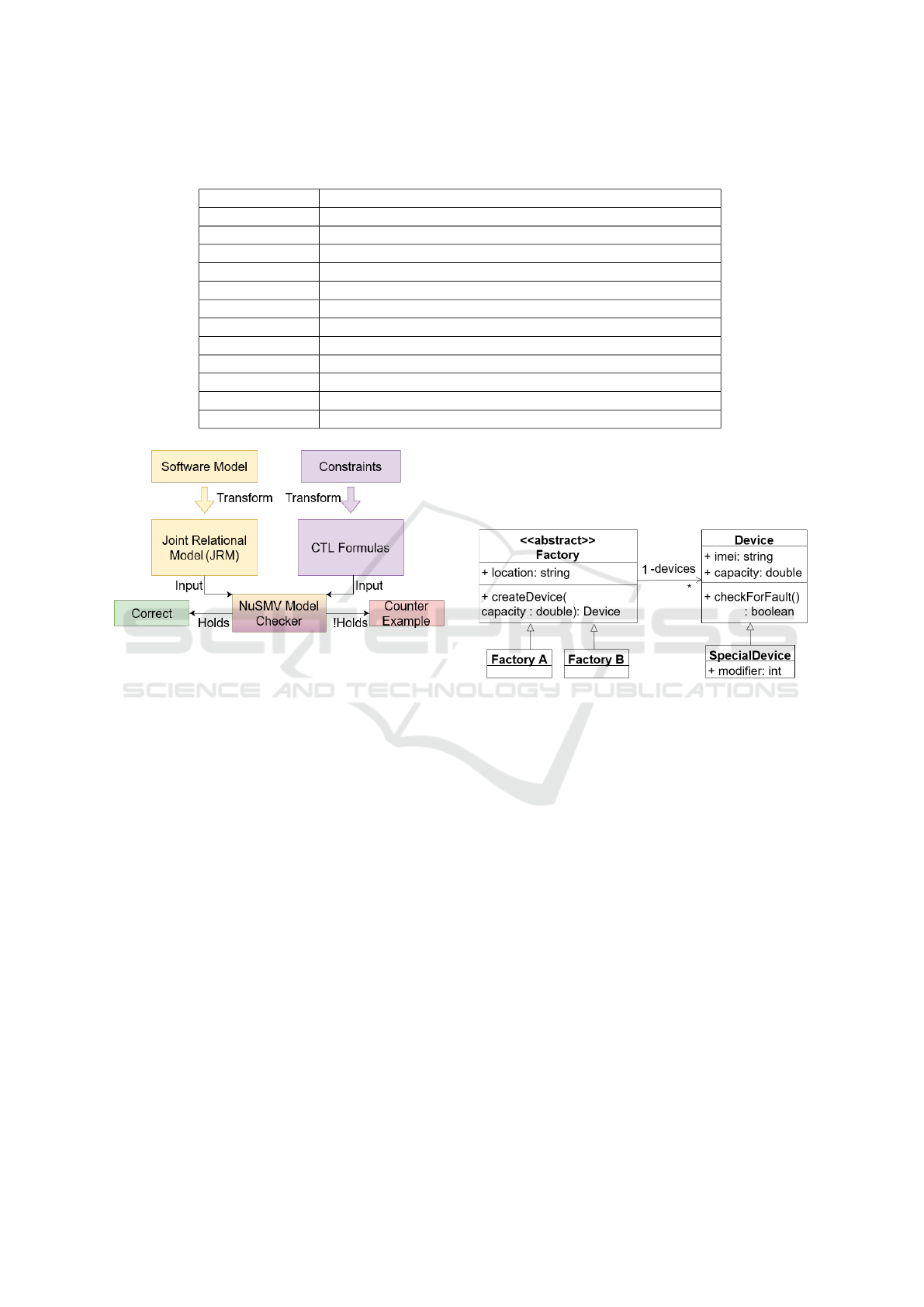
Table 1: CTL expressions and their semantics. α, β and φ are arbitrary CTL expressions, ∃ means the existential quantifier, ∀
means the universal quantifier.
CTL Expression Semantic
α ∧ β α ∧ β (logical and)
α ∨ β α ∨ β (logical or)
¬α not α (logical not)
α =⇒ β α implies beta (logical implication)
EX φ ∃ next state, where φ holds
EF φ ∃ path from the state, where φ holds eventually
EG φ ∃ path from the state, where φ holds on all states
AX φ ∀ next states, φ holds
AF φ ∀ paths from the state, φ holds eventually
AF φ ∀ paths from the state, φ holds on all states
E [α U β] ∃ path from the state, where α holds on all states until β holds
A [α U β] ∀ paths from the state, α holds on all states until β holds
Figure 2: The steps of the proposed approach for verifying
static constraints on software models.
Further along this section, we present our notions
of model elements and relations, Relational Models,
the JRM and the formalization of constraints as CTL
formulae.
4.1 Running Example - UML Class
Diagram
Throughout the rest of this section, an example UML
class diagram will be used to demonstrate the main
ideas of the verification approach. The goal of this
example is not to define an exhaustive formalization
of UML class diagrams, but to provide a compact ex-
ample and thus to make the verification concepts eas-
ier to understand. To keep things concise, the model
is deliberately minimalistic and contains only a few
elements.
The running example is described in Figure 3. The
diagram consists of five classes. The Factory class is
abstract, with two concrete subtypes: FactoryA and
FactoryB. A factory has an attribute of type string,
and a method which takes a double parameter and re-
turns an object of type Device. Factory also has an
association towards Device, intended for storing the
devices created in that factory. A device also has two
attributes with primitive types, as well as a method
that returns a boolean value. Device also has a sub-
type: SpecialDevice.
Figure 3: A UML class diagram example, to be used as a
running example further in this section.
4.2 Relational Formal Model
When defining the formal model (in the form of a
Kripke Structure), our goal is to express the struc-
ture of the original model completely. This means
that all the elements of the original model are mapped
to elements in the KS. This way, when the various
model checker algorithms employed by NuSMV tra-
verse the state-space of the model and find violations
of the constraints, the results can be mapped back
to show which element of the original model vio-
lates which constraints. To achieve this, we define
the notions of model element and relation. We de-
fine a model element as the basic building block of the
software model. In object-oriented models, such as a
UML class diagram, this typically means classes, in-
terfaces, attributes and methods. A relation is a struc-
tural relationship between model elements that con-
nect them in the model. In a UML class diagram,
this would include all the relationships that classes or
interfaces can have with one-another, meaning asso-
MODELSWARD 2023 - 11th International Conference on Model-Based Software and Systems Engineering
88
ciation, composition, aggregation, dependency, inher-
itance and interface-realization, as well as holding of
attributes and methods. To avoid confusion of termi-
nologies between the Relational Models and the orig-
inal model that must conform to the static constraints,
we will refer to the latter as the source model.
The main idea behind Relational Models is to rep-
resent every model element of the source model as
a state in the Kripke Structure. Every such state is
then labeled with an identifier that corresponds to the
model element that it represents. For example, if a
class in the source model is called “Factory”, then
in the Kripke Structure a state is created to represent
this class, labeled with the proposition “Factory”. At
this point, we assume that every model element has a
unique identifier. If this is not the case, one only needs
to define an ordering on the model elements and iden-
tify them by their assigned position in the ordering.
Relations are captured in the form of transitions
in the Kripke Structure. If a relation exists between
modeling elements m
i
and m
j
, then a transition is de-
fined in the formal model between their correspond-
ing states S
i
and S
j
. Since Kripke Structures have
limited ways to express information (only through la-
beled states and unlabeled transitions), a Relational
Model is only capable of expressing a single relation.
Thus, for each possible relation, a corresponding Re-
lational Model is created. At this point, let us gener-
alize the concept of a Relational Model.
We define a Relational Model over a set of model
elements M = {m
1
, m
2
, ..., m
k
} and Relation : M
2
7→
{0, 1} as a Kripke Structure, where:
– AP = {L|∃1 ≤ i ≤ k : m
i
[ID] = L}
– S = {IS, S
1
, S
2
, ..., S
k
}
– I = {IS}
– R = {(s, t) ∈ S|(s = IS ∧ ∃1 ≤ i ≤ k : ∄1 ≤ j ≤ k :
t = S
i
∧ Relation(m
j
, m
i
) ∨ (∃1 ≤ i, j ≤ k, i ̸= j :
S
i
= s ∧ S
j
= t ∧ Relation(m
i
, m
j
)}
– L(s ∈ S) = {L|∃1 ≤ i ≤ k : S
i
= s ∧ m
i
[ID] = L}
The set of possible atomic propositions contains
all the identifiers of the model elements. The set of
states includes a corresponding state for each model
element and an additional initial state. The transi-
tions from the initial state must be tailored to the spe-
cific source model. It should point to all other states
that are otherwise not reachable in the model. This
way, it becomes possible to actually traverse the full
model. A transition is defined between the corre-
sponding states of two model elements m
i
and m
j
if
the relation between them holds from m
i
to m
j
. This is
denoted by the defined Relation function, which maps
two model elements to 0, if the relation does not hold
from the first argument to the second, and to 1 if it
holds. Finally, every state is labeled with the identi-
fier of its corresponding model element.
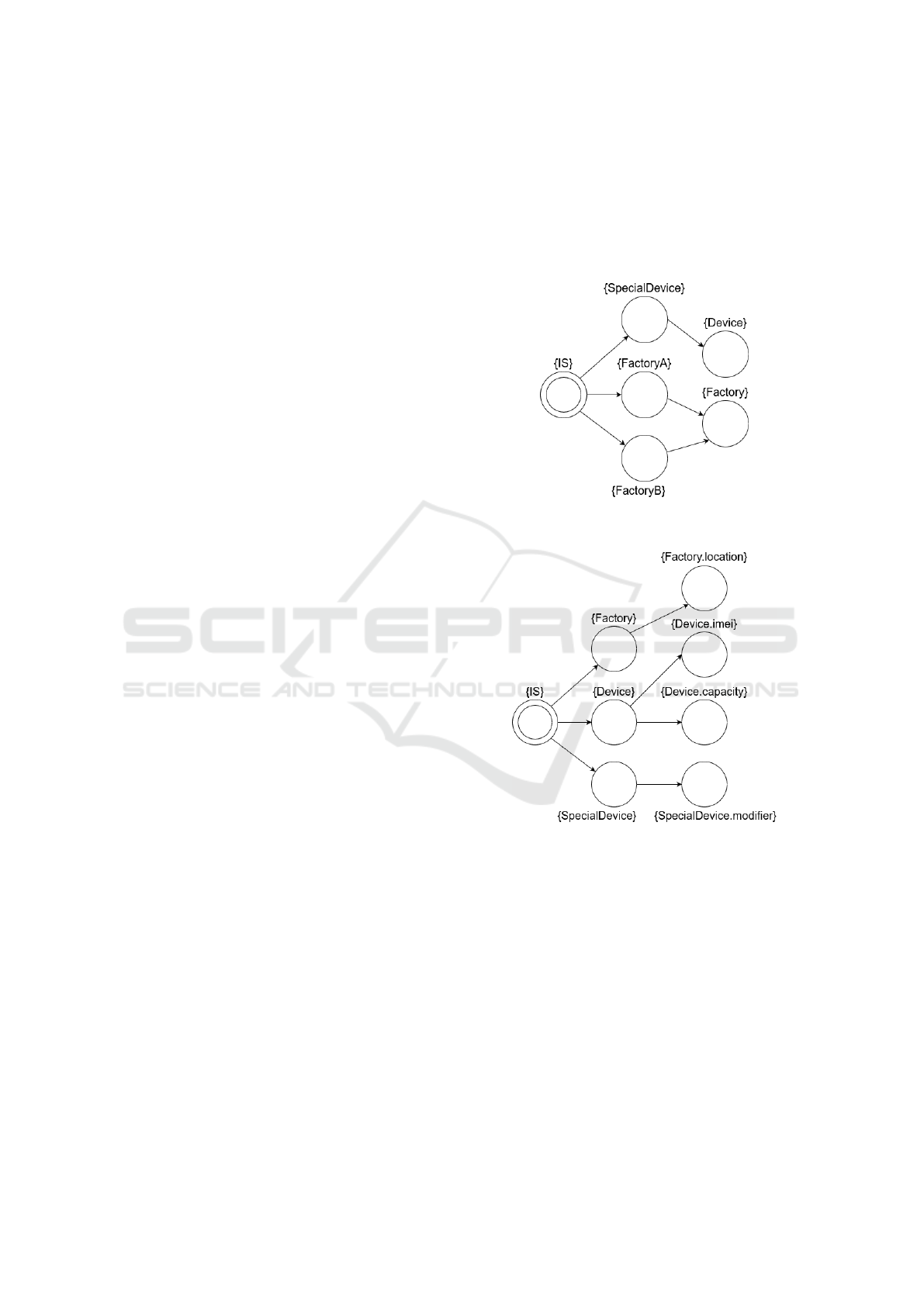
Considering the example depicted in Figure 3, for
each relation defined on UML class diagrams, a Rela-
tional Model may be generated. For instance, Figure 4
shows the inheritance model and Figure 5 shows the
attribute model of the example.
Figure 4: The inheritance model of the UML class example.
The transitions denote an inheritance relation.
Figure 5: The attribute model of the UML class example.
The transitions denote an attribute relation.
For every model element that is either the source
or the target of the given relation in the class diagram,
a state is defined labeled with the name of the model
element. Note that from now on, in examples, the
names of the states will be omitted, as they are of
no importance for the semantics of the formal model.
The states are denoted by circles, the initial state by
double circles, and the text next to a state means the
set of labels defined on that state. In these models, a
transition means inheritance or holding of an attribute
between the participants, respectively. It should be
emphasized that, in practice, it is sufficient to create
states only for those model elements that are actually
Verifying Static Constraints on Models Using General Formal Verification Methods
89

connected to another element through the given rela-
tion. This way, the state-space of the model becomes
much more concise.
4.3 Joint Relational Model
In practice, the previously defined Relational Models
may not be sufficient as models can only capture one
relation at a time. Besides the redundant representa-
tion, the problem is that constraints may typically re-
fer to multiple relations at once, requiring more than
one relation to be present in the same model in or-
der to be evaluated successfully. Moreover, multiple
relations may also be used to infer additional infor-
mation based on the relations. For instance, in the
examples depicted in Figure 3 and Figure 4, the at-
tribute model is only capable of enumerating direct at-
tributes. If both the inheritance and the attribute hold-
ing relations were present in a single formal model,
derived attributes may be handled as well. A solu-
tion is needed that is capable of capturing any (finite)
number of relations in a single Kripke Structure. The
main reason why a Relational Model could not ex-
press more than one relation is that transitions cannot
be labeled.
The idea is to simulate the labeling of transitions
with additional states. For every relation that a model
element has towards another model element, an extra
relational state is defined, labeled with the name of
the relation it represents. A transition is then added
from the source of the relation to the relational state,
and from the relational state to the target of the re-
lation. For example, if in a UML class-diagram the
class “FactoryA” inherits from the class “Factory”,
then: (i) A relational state is added, labeled with “In-
heritance”. (ii) A transition is defined from the state
labeled with “FactoryA” to the new relational state la-
beled with “Inheritance”. (iii) A transition is defined
from the relational state of “FactoryA” labeled with
“Inheritance” to the state labeled with “Factory”.
This way, relational states serve as pointers to the
target(s) of the relation. Note that relational states
cannot be merged between states but they can point
to any number of targets. For example, both the “Fac-
toryA” and “Factory” states will have their own, sep-
arate relational “Inheritance” states. But if multiple
inheritance would be possible, then only one “Inher-
itance” relational state would have to be defined for
each of them, that points to all the parent classes.
This way, it is easy to capture n-ary relations between
model elements.
The atomic propositions of a JRM consist of the
union of all the propositions of the Relational Mod-
els, extended with the set of relations for labeling the
relational states. Similarly, the states of the Relational
Models are combined, along with adding the rela-
tional states. The initial state remains the same, but
the transitions going out from it may be different (de-
noted by R
IS
). The goal here is to guarantee that the
entire state-space can be traversed. Thus, this must
be tailored specifically to the source model that is be-
ing formalized. If finding a relation that guarantees
this is not trivial or does not exist, then the transitions
from the initial state should point to all model ele-
ments that are not accessible from any relation at all
(leaves in the hierarchy). The rest of the transitions
are then defined as mentioned before: from a state to
its relational states, and from the relational states to
the target(s) of the relation. Finally, the labeling of
states remains the same as before, with the addition
of labeling the relational states with the name of the
relation they represent.
Let us now generalize this notion. Let Relations
= {Rel
1
, Rel
2
,, ... Rel
r
} be the set of all possible rela-
tions between model elements and RelationalModels
= {KS
1
, KS
2
, . . . , KS
r
} be the set of the corresponding
Relational Models. KS
i
[] denotes a certain part of KS
i
(AP – atomic propositions, S – state set, etc.), Rel
i
[S]
denotes all of the relational states combined for the re-
lation Rel
i
. We define a Joint Relational Model over
a set of model elements M, set of relations Relations,
and set of Relational Models RelationalModels as a
Kripke Structure, where:
– AP = {KS
1
[AP] ∪ ... ∪ KS
r
[AP] ∪ Relations}
– S = KS
1
[S] ∪ ... ∪ KS
r
[S] ∪ Rel
1
[S] ∪ ... ∪ Rel
r
[S]
– I = {IS}
– R = R
IS
∪ {(s, t)|∃1 ≤ i ≤ r : ∃(sKS, tKS) ∈
KS
i
[R], sRel ∈ Rel
i
[S] : (s = sKS ∧t = sRel)∨(s =
sRel ∧t = tKS)}
– L(s ∈ S) = {L|∃1 ≤ i ≤ r : (s ∈ Rel
i
[S] ∧ L =
Rel
i
) ∨ (s ∈ KS
i
[S] ∧ L = KS
i
[L](s))}
Figure 6 demonstrates how the previously men-
tioned Relational Models can be combined into a
Joint Relational Model. Every model element (that
is the source or target of at least one relation) is rep-
resented as a state. The attribute and inheritance re-
lations are then modeled by states labeled with these
relations. For example, the attributes of the class De-
vice are reachable in the model by taking the transi-
tion from the state labeled with “Device” to the next
state labeled with “Attributes”, from which a tran-
sition points to each and every attribute that Device
holds (imei and capacity).
MODELSWARD 2023 - 11th International Conference on Model-Based Software and Systems Engineering
90

Figure 6: The Joint Relational Model of the UML class ex-
ample, joining the attribute and inheritance relations.
4.4 Formalizing Constraints in CTL
The static constraints to be verified are formalized
using the previously mentioned CTL. However, in a
JRM, two core difficulties arise. Firstly, most con-
straints should only be evaluated on states represent-
ing actual model elements, not on the relational states.
Secondly, since multiple relations are now present in
the formal model, navigating between them is nec-
essary. This means that it should be possible to
prescribe that when evaluating the constraint, only
paths through certain relations should be considered.
For example, consider a constraint on a UML class-
diagram that states that inheritance hierarchies should
be acyclic. When creating the CTL formula, it must
be specified that no state can reach back to itself
through paths containing only the inheritance relation,
cycles through other relations can be perfectly valid
(e.g. bi-directional associations).
Since this problem arises from the nature of
our approach, a general solution is needed. Let
Relations = {Rel
1
, Rel
2
, . . . , Rel
r
} and R = {Rel
i
, . . . ,
Rel
k
} ⊆ Relations a subset of relations. To solve both
problems, we can define an Exclude formula in the
following way:
Exclude(R) = ¬Rel
i
∧ ¬Rel
i+1
∧ ... ∧ ¬Rel
k
(2)
By negating all the given relations (which are
atomic propositions), this formula excludes all the re-
lations in some context. For example, the problem of
only evaluating constraints on states representing ac-
tual model elements can be solved like this:
AG(Exclude(R) =⇒ φ), (3)
where φ is the formula to be verified. By using an
implication and the Exclude formula, the given rela-
tions can be excluded from the paths. Considering the
running UML class example (Figure 3), suppose we
would like to formalize the following constraints: (i)
An attribute (of primitive type, class types would be
associations) cannot hold further attributes. (ii) Inher-
itance hierarchies must be acyclic. (iii) The value of
SpecialDevice.modifier can never be 0.
Equation 4 prescribes that if a state is encountered
that is labeled with “Attributes”, then there must not
exist a next state, from which exists a second next
state which is also labeled with “Attributes”. Since
we begin from an “Attributes” state, this means that
any next state will correspond to an attribute that is
held by some model element. The second next state,
labeled with “Attributes”, would then imply that an at-
tribute holds another attribute, which is exactly what
was prohibited in the first constraint.
AG(Attributes =⇒ ¬(EXEXAttributes)) (4)
For the second constraint, for every class in the
UML class diagram, a formula should be generated.
The only difference between the generated formulae
are the labels denoted by “Class”. The reason why is
the expressive power of CTL. We have so far found
it difficult to express constraints that require “cross-
referring” some parts of the state-space. For example,
in the case of acyclic inheritance hierarchies, the con-
straint basically means that for every model element,
there must not exist a path that goes through only in-
heritance relations and leads back to itself. The part
that makes this troublesome is the “itself” part. It is
not difficult to express that for a concrete label, that
label must not be found again. But we have so far not
found it possible to express this generally, in a single
formula.
Equations 5 and 6 describe that for every state that
corresponds to a class, there must not exist a next state
labeled with ”Inheritance”, from which exists a path
through the state-space that does not touch any rela-
tional state other than “Inheritance”, and takes control
back to the given class that we have begun with. This
is accomplished by using the previously defined Ex-
clude function to ensure that on the right side of the
implication, only paths through “Inheritance” states
are considered. Note that the semantics of E [p U q]
(Table 1) are comfortably usable to express that some
states must (not) be reachable in the state-space. It
is even possible to specify conditions that must (not)
hold until the target state is (not) reached. This way,
in our approach, it is easy to express that a path must
exist between some model elements.
∀Class : AG(Class =⇒ ¬EX(I ∧ E[(φ)UClass]),
(5)
where I abbreviates Inheritance and φ denotes the
following:
φ = Exclude(Relations \ {Inheritance}) (6)
Verifying Static Constraints on Models Using General Formal Verification Methods
91

4.4.1 Handling Objects
So far, we have only formalized constraints that must
be true on the level of classes, objects were never con-
sidered. However, the third constraint states that the
value of a certain attribute can never be 0. Since the
attribute is not static, it will only gain a concrete value
when the class is instantiated. Objects can be han-
dled in the same way as classes. The idea is to simply
add the objects to the same JRM that also contains the
classes. In this case, let us extend the previous JRM
example (Figure 6) with an object. Figure 7 shows
the snippet that would be inserted additionally to the
original contents of the JRM.
Figure 7: Adding an object named Device01 to the JRM,
instantiating the class SpecialDevice. The rest of the JRM
would remain unchanged.
To handle objects, we define a new relation: In-
stantiation. We can then add an object named De-
vice01 that instantiates the class SpecialDevice. At
this point, the attributes of the parent class cannot be
reused, since for every object, its own attributes must
be available. For this reason, the attributes of De-
vice01 contain modifier that instantiates the attribute
of the parent class. To express the value of this at-
tribute, another relation is defined: Value. However,
unlike other relational states, values do not have to
point to a new state labeled with the value. Instead,
applying both the label Value and the concrete value,
in this case 0, on the same state is beneficial. This
way, less states have to be used, keeping the state-
space smaller. It should also be noted that Value states
can be reused: if another attribute also had the value
of 0, then it would not be needed to add a new state.
With this formalism in mind, it is not difficult
to formulate the third constraint. Equation 7 shows
the formula, where SD.m abbreviates SpecialDe-
vice.modifier and I abbreviates Instantiation. The for-
mula describes that for every state that instantiates the
attribute SpecialDevice.modifier, there must not exist
a next state that is labeled with both Value and 0.
AG((EX(I ∧ EXSD.m)) =⇒ ¬EX(Value ∧ 0)) (7)
Storing every value in the JRM as a relation might
cause problems in terms of performance if the number
of model elements is very high or if most of the model
elements hold some kind of value. For cases where
modeling the values is not feasible, there is another,
more straight-forward solution. NuSMV also offers
its own typesystem that supports most primitive types,
as well as basic set types and operations on them. It is
possible to define variables and store the values inside
them. Checking these values in CTL formulae is as
simple as referencing them by name and using basic
arithmetic operators on them. In our example, instead
of modeling the value relation in the JRM, we would
store the value of Device01.modifier in a variable Val-
ueDevice01Modifier, and check its non-nullity.
We have created a demo application
1
that demon-
strates the formalization and verification of the run-
ning UML class diagram in practice.
5 CONCLUSIONS
In this work, we have proposed a general approach for
verifying static constraints on software models.
A formal Kripke Structure is created that captures
the static aspects of the original software model, the
constraints are formalized using CTL and a model
checker tool, NuSMV is used to verify whether
the formalized CTL expressions hold on the formal
model. The approach was presented through a run-
ning UML class diagram example.
The main strength of the proposed approach lies in
its formal aspect. Since a cutting-edge model checker
tool (NuSMV) is reused, the checking of models is
fully automatic, and formal proof is given that the
model satisfies the constraints. It is guaranteed to
find any violations of the formalized constraints. If
no violations are found, the constraint is guaranteed
to hold. The approach is general and independent of
the modeling language of the source model. While
this is mostly true for OCL and its variants as well,
defining a mapping between the source model and the
JRM is easier and takes less effort than implementing
an OCL interpreter for the given modeling language.
A consequence of the generality is that the approach
becomes independent of the concrete model checker
behind it. It currently uses NuSMV, but could easily
be extended to use a different model checker or sup-
port multiple options.
The main weakness of the approach is the expres-
sive power of CTL. Constraints that would require
cross-referencing parts of a CTL expression are dif-
ficult to handle. This could be alleviated by defin-
ing transformations on the formal Kripke Structure.
1
https://github.com/NorbertSomogyi/
FormalModelVerificationDemo
MODELSWARD 2023 - 11th International Conference on Model-Based Software and Systems Engineering
92

Temporarily manipulating the structure of the formal
model (such as adding new states and transitions, or
changing existing ones) may make it easier to nav-
igate the model and handle CTL expressions that
would otherwise prove difficult. The second weak-
ness is that the approach is mainly designed to deal
with static constraints on the source model. It is not
capable of interpreting functions. Thus, it is not in-
tended to verify dynamic behavior. If that is required,
a static view of the dynamic behavior would be re-
quired, such as Abstract Syntax Trees (AST). Finally,
defining CTL expressions requires proficiency in for-
mal verification. For this reason, in the future, a Do-
main Specific Language (DSL) (Fowler, 2010) must
be created to hide the complexity of writing CTL ex-
pressions from the model designer.
In terms of future work, thoroughly evaluating
the expressive power of CTL on real-world models
and constraints is our main priority. Depending on
the results of the evaluation, an extension of CTL
or a whole new language might be needed. In the
first case, by introducing model transformations on
Kripke Structures, constraints that are difficult to ex-
press through CTL may become easier. In the sec-
ond case, along with the new language, significant
enhancements to a model checker tool might be nec-
essary. The performance of the approach will also be
evaluated, making sure it is efficient enough to be ap-
plicable in practice, even on larger models and a sig-
nificant amount of constraints to be verified.
REFERENCES
Anastasakis, K., Bordbar, B., Georg, G., and Ray, I.
(2007). Uml2alloy: A challenging model transfor-
mation. In ACM/IEEE International Conference on
Model Driven Engineering Languages and Systems,
pages 436–450.
Behrmann, G., David, A., and Larsen, K. (2004). A tutorial
on uppaal. In International School on Formal Meth-
ods for the Design of Computer, Communication and
Software Systems, volume 3185, pages 200–236.
Brucker, A. and Wolff, B. (2008). Hol-ocl: A formal proof
environment for uml/ocl. pages 97–100.
Cabot, J., Calegari, D., Claris
´
o, R., Gogolla, M., Vallecillo,
A., and Willink, E. D. (2021). A swot analysis of the
object constraint language. pages 178–184.
Cabot, J., Claris
´
o, R., and Riera, D. (2007). Umltocsp: A
tool for the formal verification of uml/ocl models us-
ing constraint programming. In Proceedings of the
Twenty-Second IEEE/ACM International Conference
on Automated Software Engineering, ASE ’07, page
547–548, New York, NY, USA. Association for Com-
puting Machinery.
Cabot, J. and Gogolla, M. (2012). Object constraint lan-
guage (ocl): A definitive guide. volume 7320, pages
58–90.
Cimatti, A., Clarke, E., Giunchiglia, E., Giunchiglia, F., Pi-
store, M., Roveri, M., Sebastiani, R., and Tacchella,
A. (2002a). Nusmv 2: An opensource tool for sym-
bolic model checking. 14th International Conference,
CAV, Copenhagen, Denmark.
Cimatti, A., Giunchiglia, E., Pistore, M., Roveri, M., Sebas-
tiani, R., and Tacchella, A. (2002b). Integrating bdd-
based and sat-based symbolic model checking. vol-
ume 2309.
Fowler, M. (2010). Domain Specific Languages. Addison-
Wesley Professional, 1st edition.
Jackson, D. (2012). Software Abstractions: Logic, Lan-
guage, and Analysis. The MIT Press.
Mahajan, Y., Fu, Z., and Malik, S. (2004). Zchaff2004: An
efficient sat solver. volume 3542, pages 360–375.
MOF (2005). OMG: MetaObject Facility.
http://www.omg.org/mof/. Accessed:2022-11-24.
Muller-olm, M., Schmidt, D., and Steffen, B. (1999).
Model-checking: A tutorial introduction. volume
1694, pages 330–354.
Nobakht, M. and Truscan, D. (2013). Tool Support for
Transforming UML-Based Specifications to UPPAAL
Timed Automata. Turku Centre for Computer Sci-
ence (TUCS). TUCS Technical Report No 1087, June
2013.
Przigoda, N., Soeken, M., Wille, R., and Drechsler, R.
(2016). Verifying the structure and behavior in um-
l/ocl models using satisfiability solvers. IET Cyber-
Physical Systems: Theory & Applications, 1.
Shaikh, A., Claris
´
o, R., Wiil, U. K., and Memon, N. (2010).
Verification-driven slicing of uml/ocl models. In Pro-
ceedings of the IEEE/ACM International Conference
on Automated Software Engineering, ASE ’10, page
185–194, New York, NY, USA. Association for Com-
puting Machinery.
S
¨
orensson, N. and Een, N. (2005). Minisat v1.13-a sat
solver with conflict-clause minimization. Interna-
tional Conference on Theory and Applications of Sat-
isfiability Testing.
UML (2017). OMG: Unified Modeling Language.
https://www.omg.org/spec/UML/2.5.1/PDF/.
Accessed:2022-11-24.
Vaziri, A. and Jackson, D. (2003). Some shortcomings of
ocl, the object constraint language of uml.
Verifying Static Constraints on Models Using General Formal Verification Methods
93
