
3D Mapping of Indoor Parking Space Using Edge Consistency
Census Transform Stereo Odometry
Junesuk Lee and Soon-Yong Park
a
School of Electronic and Electrical Engineering, Kyungpook National University, Daegu, South Korea
Keywords: 3D Mapping, 3D Reconstruction, 3D Scanning, Visual Odometry, Parking Ramp, Parking Space.
Abstract: In this paper, we propose a real-time 3D mapping system for indoor parking ramps and spaces. Visual
odometry is calculated by applying the proposed Edge Consistency Census Transform (ECCT) stereo
matching method. ECCT works strongly in repeated patterns and reduces drift errors in the vertical direction
of the ground caused by Kanade-Lucas-Tomasi stereo matching of VINS-FUSION algorithm. We propose a
mobile mapping system that uses a stereo camera and 2D lidar for data set acquisition. The parking ramp and
spaces dataset are obtained using the mobile mapping system and are reconstructed using the proposed system.
The proposed system performs the 3D mapping of the parking ramp and spaces dataset that is obtained using
the mobile mapping system. We present the error of the normal vector with respect to the ground of the
parking space as a quantitative evaluation for performance comparison with the previous method. Also, we
present 3D mapping results as qualitative results.
1 INTRODUCTION
With the rapid development of technologies related to
autonomous driving, the 3D mapping technology of
real space is being actively researched. Self-driving
cars use the HD map built in advance to safely drive
in urban and highway environments, estimate the
location of the car, plan the driving route, and safely
drive to the destination (Kim et al., 2021; Ding et al.,
2021). To create an HD map, the vehicle is combined
with the camera, lidar, IMU, and GPS sensor to scan
the surrounding environment. Such a device is called
Mobile Mapping System (MMS) (Roh et al., 2016).
In addition, the HD map is provided information such
as traffic lights, traffic signs, and lanes that can affect
the localization and path planning of autonomous
vehicles (Elhousni et al., 2020). Considering the
complete driving of the autonomous vehicle, the
vehicle must be driven from the parked location to the
parking spaces of the destination. Autonomous valet
parking research (Qin et al., 2020; Chirca et al., 2015)
aims to park a vehicle at a certain spot in the parking
spaces. In addition to these studies, the problem of
entering the parking space inside the building from
the outdoor environment should be considered. In
most cases of underground or above-ground parking
a
https://orcid.org/ 0000-0001-5090-9667
included inside a building, it is necessary to pass
through the parking ramp. In general, it is difficult to
perform localization in the computer vision field
because the parking ramp section has few textures
and similar structures. Especially, in the case of a
parking ramp in a building, if the width is narrow and
the illumination is low, sit is difficult for autonomous
vehicles to enter. Therefore, as one method for safe
driving on the parking ramp, there is providing
information on the width, height, length, curvature,
and slope of the ramp section. In the International
Building Code (International Code Council, 2018),
(a) Parking ramp (b) Parking space
Figure 1: Experimental results of the 3D reconstruction for
the parking ramp and space by the proposed 3D mapping
system.
Lee, J. and Park, S.
3D Mapping of Indoor Parking Space Using Edge Consistency Census Transform Stereo Odometry.
DOI: 10.5220/0011789100003417
In Proceedings of the 18th International Joint Conference on Computer Vision, Imaging and Computer Graphics Theory and Applications (VISIGRAPP 2023) - Volume 5: VISAPP, pages
1015-1020
ISBN: 978-989-758-634-7; ISSN: 2184-4321
Copyright
c
2023 by SCITEPRESS – Science and Technology Publications, Lda. Under CC license (CC BY-NC-ND 4.0)
1015
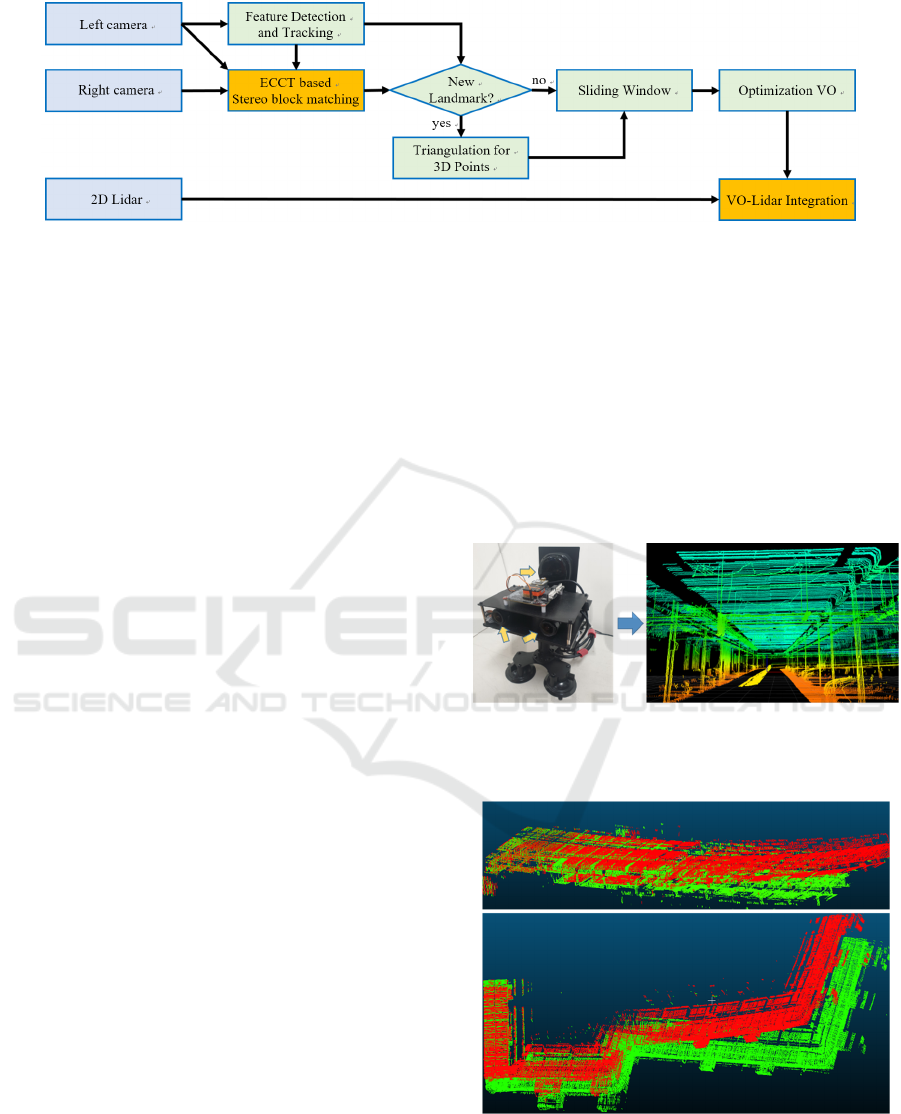
Figure 2: System overview of 3D reconstruction for the parking ramp and parking spaces.
the building law for parking ramp sections suitable
for automobile facilities have been established.
International building codes include width, height,
length, curvature, and slope for ramp sections of
buildings. To measure this information, 3D spatial
scanning must be accompanied.
In this paper, we propose a 3D mapping system
for parking ramps and parking spaces and a mobile
mapping device composed of a stereo camera and 2D
lidar. The 3D mapping system calculates visual
odometry using the proposed ECCT stereo-matching
method. The overall system structure of visual
odometry is based on VINS-FUSION (Qin et al.,
2019). In the parking spaces mapping process, VINS-
FUSION's Kanade-Lucas-Tomasi (KLT) stereo
matching method causes a large drift error in the
vertical direction of the ground (Bouguet, 1999). To
reduce this drift error, we estimate the visual
odometry using the proposed ECCT stereo matching.
ECCT stereo matching is robust to repeated patterns
and symmetrical patterns because it considers the
continuity and rotation of the edges for the matching
block. Next, the point data of the 2D lidar is projected
into the 3D space using the 3D coordinate
transformation matrix between the stereo camera and
the 2D Lidar sensor. Fig. 1 shows the 3D mapping
result generated by projecting 2D lidar data into 3D
space.
2 SYSTEM OVERVIEW
The proposed 3D mapping device configuration is
shown in Fig. 3. The device consists of a stereo
camera and 2D lidar, the stereo camera acquires
synchronized data through a hardware trigger, and the
2D lidar data acquire synchronized data through
software synchronization with the stereo camera. And
the system overview of the real-time 3D mapping is
shown in Fig. 2. This system takes stereo images as
inputs and estimates stereo-based visual odometry
(VO). The reference coordinate system of the
estimated visual odometry is the left camera
coordinate system. In the experiments, we found that
VINS-FUSION had a drift problem in the vertical
direction of the ground as shown in Fig. 4. VINS-
FUSION performs stereo matching based on the KLT
feature tracker. We improve the drift problem in the
vertical direction of the ground by applying the
proposed ECCT stereo matching method. The 2D
lidar data is projected onto the 3D space through
coordinate system transformation for the estimated
VO.
Proposed ing device 3D reconstruction of the parking space
Figure 3: Proposed 3D mapping device for the parking
ramp and parking space.
Figure 4: The drift problem with respect to the vertical
direction of the ground. The red point cloud is the result of
using KLT-based stereo matching. The green point cloud is
the result of using the proposed ECCT stereo-matching
method.
2D Lida
r
Camera
VISAPP 2023 - 18th International Conference on Computer Vision Theory and Applications
1016

3 STEREO BLOCK MATCHING
We apply the spare stereo matching method
considering real-time applications. A stereo matching
point is searched for the tracked feature points
between the previous frame and the current frame.
The KLT method is used to trace the feature points
between the previous frame and the current frame.
We propose ECCT stereo-matching for stereo block
matching. This method extends the traditional census
transform (Zabih and Woodfill, 1994). The proposed
method assumes non-rectified stereo images.
Rectified stereo images can be easily searched using
the epipolar line range search. However, a large part
of the image is removed in the process of creating a
rectified stereo image. Therefore, the field of view
advantage is lost when used in wide-angle images
(Lv, 2017). We use a wide-angle camera to take
advantage of the wide-angle FOV. We use a window
kernel of size n n for stereo matching, where n is
an odd value of three or greater. The left image is used
as a reference image and the search for stereo
matching points in the right image. The search range
searches 𝑤
ℎ
from the left image to the
reference pixel position of the right image. After
searching all pixels in the search range, the pixel point
with the lowest matching cost value is selected as the
stereo matching point. In this paper, n is three and
𝑤
ℎ
is 21 7.
3.1 Census Transform
Census Transform (CT) creates a binary pattern of 0
and 1 in a window block by comparison between the
central pixel and the surrounding pixels. Generates 1
if the center pixel is greater than the neighboring
pixel, and 0 if it is less than the neighboring pixel.
Then, the matching cost is calculated through the
Hamming distance (Liu and Na, 2022) of the
generated binary pattern. However, Census
Transform Cost (CTC) can produce the same cost
results despite different patterns within the search
area. This problem often occurs in the repeated
pattern (Liu and Collins, 2000) area. Dense stereo
matching compensates for this problem mostly in the
depth refinement stage (Lee et al., 2012). However,
our system must perform spare stereo matching while
satisfying real-time performance. Fig. 5 shows an
example of the case where the same CTC exists in a
size with a window size of 3. If multiple blocks with
the same matching cost are found within the search
area, matching blocks can be selected in two ways.
The first is to randomly select among the same
matching cost blocks. The second is to select a
matching cost block suitable for the constraint by
adding a constraint. We adopt the method of selecting
the final matching point by adding a constraint.
Figure 5: Example of the equal Census Transform cost for
different patterns.
3.2 Edge Consistency Census
Transform
We propose ECCT stereo-matching to improve CT
stereo-matching. We are motivated by fast features
(Rosten et al., 2008). The flowchart of the proposed
method is shown in Fig. 2. The consistency of the
edge area of the binary pattern generated by CT is
checked. The edge in the window means the yellow
cell in Fig. 6. The order of calculating Edge
Consistency Census Transform Cost (ECCTC) is as
follows: First, the maximum number of consecutive
zeros is searched from the binary bit calculated by CT
and defined as the Max count of edge consistency.
Assuming that the starting point and the ending point
are connected, search for the number of consecutive
zeros in clockwise order as shown in Fig. 6. Then, the
difference between the total number of edge cells and
the max count of edge consistency is calculated. The
total number of edge cells (𝑅
) is defined by (1).
Fig. 7 shows an example of calculating ECCTC. In
the 1st row of Fig. 7, The max count of edge
consistency in the binary bit is 5. And 𝑅
is 8,
ECCTC is 8-5=3. Similarly, in the second row of Fig.
7, the max count of edge consistency of binary bits is
2 and ECCTC is 8-2=6. If the consistency of the edge
is perfect, the max count of edge consistency is the
same as 𝑅
. That is, ECCTC becomes 0. Our final
stereo matching cost (𝑇
) is calculated as the sum
of CTC (𝑇
) and ECCTC (𝑇
) as in (2). The
Figure 6: Example of the equal Census Transform cost for
different patterns.
3D Mapping of Indoor Parking Space Using Edge Consistency Census Transform Stereo Odometry
1017
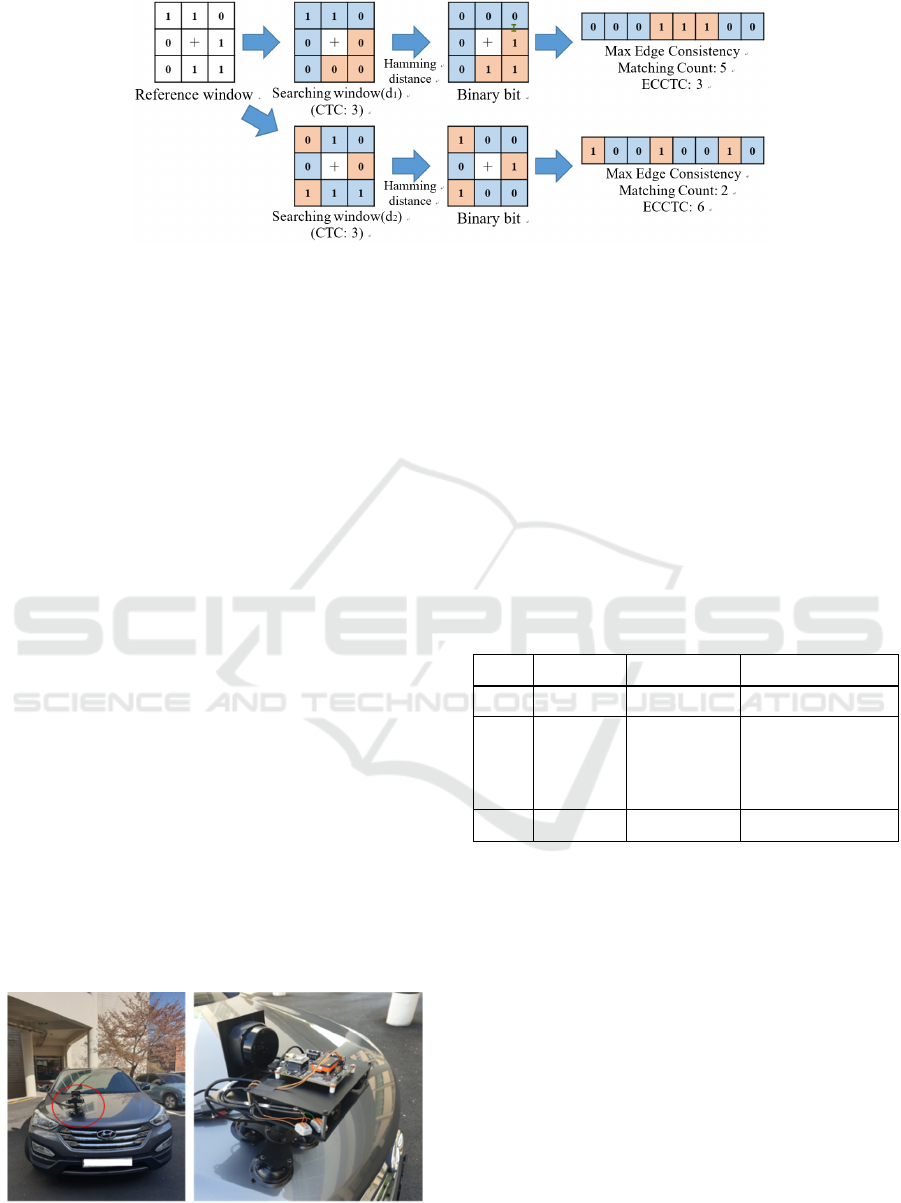
Figure 7: Example of the equal Census Transform cost for different patterns.
proposed ECCT method has an efficient amount of
computation because it calculates only the edge part
even if the size of the window size increases.
𝑅
𝑛1
∗4 (1)
𝑇
𝑇
𝑇
(2)
4 VO-LIDAR INTEGRATION
The data from both sensors can be integrated using
the coordinate system transformation matrix between
the camera and lidar. We project the 2D lidar data
onto the visual odometry of the same time. This
method can express 3D space using visual odometry
and 2D lidar. Equation 3 is a formula for this. 𝑃
𝑥
,𝑦
,1,1
represents a point in lidar data
measured at time 𝑡 based on the 2D lidar coordinate
system. 𝑇
represents the 4x4 transformation matrix
between the camera sensor and the 2D lidar sensor.
The coordinate system calibration between the two
sensors was mechanically corrected. 𝑇
is the 4x4
transformation matrix of the camera sensor for time t
from the world coordinate system. So 𝑃
𝑥
,𝑦
,𝑧
,1
is world coordinate data for 𝑃
measured from 2D lidar at time 𝑡.
𝑃
𝑇
𝑇
𝑃
(3)
Figure 8: Mobile Mapping System to acquire data of
parking spaces and ramp.
5 EXPERIMENTAL RESULTS
To evaluate the performance of the proposed system,
we acquired the dataset from 5 parking ramps and 3
parking spaces by attaching a 3D mapping system to
the car as shown in Fig. 8. Each sensor of the
proposed 3D scanning device is shown in Table 1.
Our camera acquires 20 fps synchronized 688x650
image size data. 2D lidar acquires synchronized data
at 10 fps. Computer specs are intel-core i7-9700k @
3.60 GHz, 16GB RAM.
Table 1: Sensor information of the proposed 3D scanning
device.
Type Manufacture Model description
Camera FILR GS-U3-41C6C-C Global shutter camera
Lens
KOWA LM4NCL
Focal length (3.5mm)
Angle of view
[HorVer]
(117.7°86.7°)
2D Lidar
SLAMTech RPLIDAR S2 1 channel (360 FOV)
We compare the slopes of three parking spaces
and present quantitative data for performance
comparison between the ECCT stereo matching
method and the KLT stereo matching method. Since
we do not have exact Ground-Truth (GT) slope
information for each parking space, we set two
prerequisites. As the first prerequisite, the angle of
inclination of the parking spaces is assumed to be zero
degrees. As a second prerequisite, we assumed that
the normal vector of the plane fitting for the area
where the scanned results of the two methods
completely overlapped is the normal vector of GT.
We calculate the normal vector for two methods of
plane fitting and calculate the angle error by
calculating the dot product of the GT's normal vector.
Table 2 shows the angular error between the normal
vector to the ground in GT and the normal vector to
VISAPP 2023 - 18th International Conference on Computer Vision Theory and Applications
1018
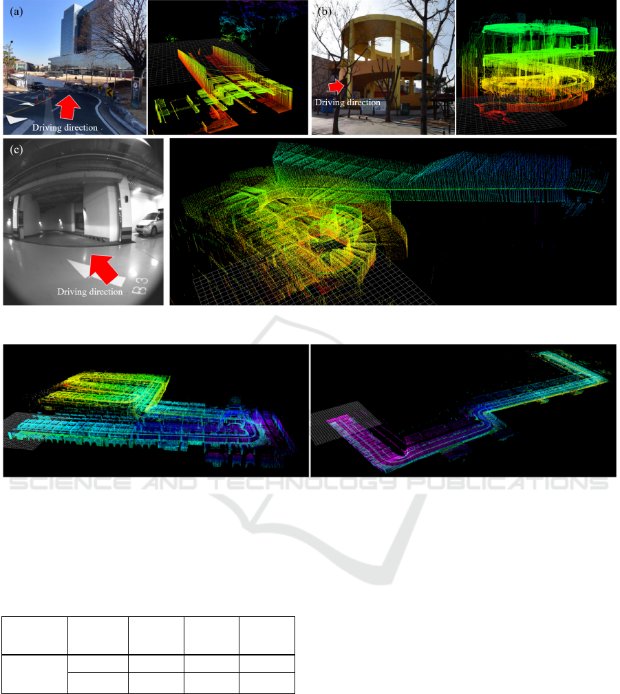
Figure 9: The 3D mapping result for the parking ramps.
Figure 10: The 3D mapping result for the parking spaces.
the 3D reconstructed point cloud ground. The
proposed method shows better performance at the
angle error.
Table 2: Angle Error between normal vectors of the ground
plane.
Stereo
matching
Method
Dataset
1
Dataset
2
Dataset
3
Angle
Error
(degree)
KLT 7.33994 12.26250 10.19682
ETTC 1.79957 2.62571 5.33328
Fig. 9 shows the 3D reconstruction results for the
three parking ramp section datasets. The left image of
each dataset result shows the entry direction of the
MMS. The image on the right shows the height ramp
map results for the reconstructed point cloud data. Fig.
9(a) is the result of the parking ramp dataset for the
scenario going down from the ground floor to the first
basement floor. Fig. 9(b) is the result of the parking
ramp data set for the scenario going up from the 1st
floor to the 4th floor. Fig. 9(c) is the result of the
parking ramp data set for the scenario going up from
the 3rd basement floor to the 1st floor above the
ground. Fig. 10 shows the 3D restoration results for a
parking space without a slope.
6 CONCLUSIONS
This paper presents a device consisting of a
synchronized stereo camera and a 2D Lidar sensor
and the 3D reconstruction method for parking ramp
sections and parking spaces in real time. The
proposed 3D reconstruction method integrates data
by projecting 2D lidar data based on stereo-based
visual odometry. Visual odometry is based on VINS-
Fusion. The odometry using VINS-Fusion's KLT-
based stereo matching can cause drift in the vertical
direction to the ground. So, we proposed and
integrated the Edge Consistency Census Transform
stereo matching method. Edge Consistency Census
Transform is designed to be robust against repeated
3D Mapping of Indoor Parking Space Using Edge Consistency Census Transform Stereo Odometry
1019

patterns by extending the traditional Census
Transform and adding constraints on the consistency
of the Census block edge. The proposed method
scanned the parking ramp section and parking space
and presented qualitative and quantitative results. In
future research, we plan to improve the performance
of odometry by combining the wheel odometry and
an IMU sensor.
ACKNOWLEDGMENT
This work was supported in part by Basic Science
Research Program through the National Research
Foundation of Korea(NRF) funded by the Ministry of
Education (No. 2021R1A6A1A03043144) and part
by the NRF grant funded by the Korea government
(MSIT)(No. 2021R1A2C2009722).
REFERENCES
Bouguet, J. (1999). Pyramidal implementation of the lucas
kanade feature tracker.
Chirca, M., Chapuis, R., & Lenain, R. (2015). Autonomous
Valet Parking System Architecture. 2015 IEEE 18th
International Conference on Intelligent Transportation
Systems, 2619-2624.
Ding, W., Zhang, L., Chen, J., & Shen, S. (2021).
EPSILON: An Efficient Planning System for
Automated Vehicles in Highly Interactive
Environments. IEEE Transactions on Robotics, 38,
1118-1138.
Elhousni, M., Lyu, Y., Zhang, Z., & Huang, X. (2020).
Automatic Building and Labeling of HD Maps with
Deep Learning. AAAI Conference on Artificial
Intelligence.
International Code Council, (2018). Overview of the
International Building Code, https://codes.iccsafe.org/
content/IBC2018.
Kim, K., Cho, S., & Chung, W. (2021). HD Map Update for
Autonomous Driving With Crowdsourced Data. IEEE
Robotics and Automation Letters, 6, 1895-1901.
Lee, S., Park, Y., & Suh, I.H. (2012). Dependable dense
stereo matching by both two-layer recurrent process
and chaining search. 2012 IEEE/RSJ International
Conference on Intelligent Robots and Systems, 5191-
5196.
Liu, P., & Na, J. (2022). A Generalized Hamming Distance
of Sequence Patterns.
Liu, Y., & Collins, R.T. (2000). A computational model for
repeated pattern perception using frieze and wallpaper
groups. Proceedings IEEE Conference on Computer
Vision and Pattern Recognition. CVPR 2000 (Cat.
No.PR00662), 1, 537-544 vol.1.
Lv, Q., Lin, H., Wang, G., Wei, H., & Wang, Y. (2017).
ORB-SLAM-based tracing and 3D reconstruction for
robot using Kinect 2.0. 2017 29th Chinese Control And
Decision Conference (CCDC), 3319-3324.
Qin, T., Chen, T., Chen, Y., & Su, Q. (2020). AVP-SLAM:
Semantic Visual Mapping and Localization for
Autonomous Vehicles in the Parking Lot. 2020
IEEE/RSJ International Conference on Intelligent
Robots and Systems (IROS), 5939-5945.
Qin, T., Pan, J., Cao, S., & Shen, S. (2019). A General
Optimization-based Framework for Local Odometry
Estimation with Multiple Sensors. ArXiv,
abs/1901.03638.
Roh, H.C., Jeong, J., Cho, Y., & Kim, A. (2016). Accurate
Mobile Urban Mapping via Digital Map-Based SLAM.
Sensors (Basel, Switzerland), 16.
Rosten, E., Porter, R.B., & Drummond, T. (2008). Faster
and Better: A Machine Learning Approach to Corner
Detection. IEEE Transactions on Pattern Analysis and
Machine Intelligence, 32, 105-119.
Zabih, R., & Woodfill, J.I. (1994). Non-parametric Local
Transforms for Computing Visual Correspondence.
European Conference on Computer Vision.
VISAPP 2023 - 18th International Conference on Computer Vision Theory and Applications
1020
