
Computational Study of Particle Separation Based on Inertial Effects in
Rectangular Serpentine Channels with Different Aspect Ratios
Al
ˇ
zbeta Bug
´
a
ˇ
nov
´
a
1 a
and Ivan Cimr
´
ak
1,2 b
1
Cell-in-fluid Biomedical Modelling & Computations Group, Faculty of Management Science and Informatics,
University of
ˇ
Zilina, Slovakia
2
Research Centre, University of
ˇ
Zilina, Slovakia, Slovak Republic
Keywords:
Inertial Microfluidics, Rectangular Cross-Section, Particle Separation, Focusing Length.
Abstract:
Inertial effects in straight and curved microfluidic channels have great potential for separation of particles of
different sizes. the geometry of the channels influences the separation. In this work we consider a serpentine
channel with rectangular cross section of different sizes to explore the influence of aspect ratio on focusing
performance and particle separation possibilities. Particle trajectories of different sizes are studied by means
of a computational simulations. We show that low-aspect ratio offers more possibilities for separation in terms
of particle sizes as well as in terms of higher throughput.
1 INTRODUCTION
The inertial migration of particles in a flow through
a cylindrical tube was first observed by (Segr
´
e and
Silberberg, 1961). In their experiments, spherical
particles migrated to an annulus located about 0.6
times of tube radius between centerline and pipe
wall. Subsequently, many research studies were fo-
cused to understand the underlying physics of this
phenomenon through experimental studies, theoreti-
cal analyses and numerical simulations (McLaughlin,
1993; Chun and Ladd, 2006; Hood et al., 2015) and
the references therein.
After big leap in microfluidics in last decades,
where the size of patterned micro-channel is compa-
rable to that of the suspended particles (so that inertial
migration can be more obvious within a short channel
length), inertial effects have found their use in practi-
cal applications in medicine and biomedicine e.g. re-
covery of rare cells from blood (Tanaka et al., 2012),
separation of particles by deformability for instance
diseased red blood cells from healthy ones or search
for sepsis markers (Gossett et al., 2012).
Inertial microfluidics provide precise manipula-
tion with immersed particles or cells, simple structure
and high throughput. In contrast to active microflu-
idic manipulation technologies (Cetin and Li, 2011;
a
https://orcid.org/0000-0001-6772-2970
b
https://orcid.org/0000-0002-0389-7891
Forbes and Forry, 2012; Li et al., 2013) where exter-
nal force fields (electric, magnetic, acoustic) are sup-
plied to control the motion of target particles or cells,
inertial microfluidics is a passive manipulation tech-
nology, and it employs intrinsic hydrodynamic force
for manipulation. Therefore, the operation of inertial
microfluidics is very simple and robust, and the cost
of inertial microfluidic device is low.
Computational models provide effective way for
prototyping the correct geometries of the channels.
(Rasooli and C¸ etin, 2018) developed a Lagrangian
model using COMSOL Multiphysics to solve the con-
tinuous phase and simulate particle trajectories in a
spiral microchannel. (Jiang et al., 2016) explored
the particle focusing mechanisms of a symmetric ser-
pentine microchannel using model based on a lattice
Boltzmann method. (Ying and Lina, 2020) studied
special zig-zag shape of serpentine channel conclud-
ing several advantages of this type of channel com-
pared to squared or curved serpentines. Their results
indicate that the zigzag channel has the best focusing
effect at a high Reynolds number and that the serpen-
tine channel is second in terms of performance.
Contents of This Work
In this work we focus on studying how different as-
pect ratio of the channel cross section affects the even-
tual focusing positions of particles with two different
sizes. In (Ying and Lina, 2020) the authors consid-
284
Bugá
ˇ
nová, A. and Cimrák, I.
Computational Study of Particle Separation Based on Inertial Effects in Rectangular Serpentine Channels with Different Aspect Ratios.
DOI: 10.5220/0011788200003414
In Proceedings of the 16th International Joint Conference on Biomedical Engineering Systems and Technologies (BIOSTEC 2023) - Volume 3: BIOINFORMATICS, pages 284-291
ISBN: 978-989-758-631-6; ISSN: 2184-4305
Copyright
c
2023 by SCITEPRESS – Science and Technology Publications, Lda. Under CC license (CC BY-NC-ND 4.0)
ered the cross section with dimensions 80× 40µm. We
added two more cases to see whether more square-
like cross section or a cross section with lower as-
pect ratio will affect the stable positions. Therefore
we picked rectangular cross sections 60 × 52µm and
100 × 32µm, see Figure 7. All three cases have sim-
ilar area of around 3100µm
2
. This ensures that with
the same volumetric flow we get similar maximal ve-
locities in the channels.
In Section 2 we briefly provide theoretical aspects
of inertial focusing. In Section 3 we describe the
physical model and its numerical implementation to-
gether with several technical details about the experi-
mental setup. In Section 4 we provide computational
results and in the last section we discuss the results.
2 PRINCIPLES OF INERTIAL
FOCUSING
Particle focusing in straight channels about 60% away
from the tube centerline is caused by a balance of in-
ertial shear gradient lift forces pushing the particles
towards the wall and a wall repulsion forces caused
by an increased pressure between the particles and
the wall (Matas et al., 2009). Altering the channel
cross section or curving the channel into serpentine
or spiral geometries changes the number and location
of lateral equilibrium positions and can accelerate lat-
eral focusing of particles (Martel and Toner, 2014).
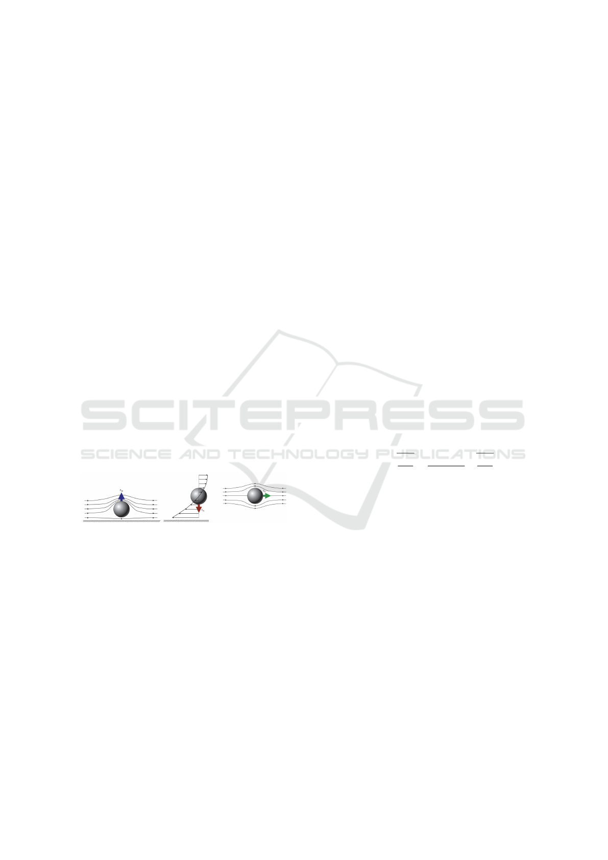
The forces responsible for such behaviour are three-
Figure 1: Competing inertial forces. Reprinted from (Mar-
tel and Toner, 2014) with permissions.
fold: the wall interaction lift forces, the shear gradient
lift forces and the secondary-flow induced Dean drag
forces, see Figure 1. As the streamlines are diverted
toward the side of the particle away from the wall, the
fluid accelerates, causing low pressure on the top and
higher pressure on the wall side of the particle, which
generates the wall interaction force, Figure 1 on the
left. The formula giving the magnitude of the wall
induced force is
F
LW
= C
W
ρU
2
max
a
6
/D
4
h
, (1)
where C
W
is a lift coefficient dependent on particle
position and on Reynolds number (Di Carlo et al.,
2009), ρ is the fluid density, U
max
is the maximal fluid
velocity, a is the particle diameter, and D
h
is the hy-
draulic diameter of the channel.
A typical microfluidic velocity profile is parabolic
and, thus, curved. A particle at a position in such
a flow will experience velocities of different magni-
tudes on either side. The fluid flow around the parti-
cle must compensate for this difference and induces
a force on the particle directed toward the side of the
particle with a higher relative velocity (normally to-
ward the walls of a microfluidic channel or areas of
increasing shear), Figure 1 in the middle. This shear
induced lift force has magnitude
F
LS
= C
S
ρU
2
max
a
3
/D
h
, (2)
here C
S
is a shear coefficient dependent on particle po-
sition and on Reynolds number (Di Carlo et al., 2009).
In curved channels, the centrifugal force gener-
ates a secondary flow that is perpendicular to the main
flow direction. Normally, this flow is two orders mag-
nitude weaker than the main flow, however it is suf-
ficient to create the drag around the particles causing
transversal motion across the cross section, Figure 1
on the right. The formula for the evaluation of Dean
force takes the form
F
D
= 3πµaU
D
, (3)
where averaged Dean velocity can be approximated
by (Ookawara et al., 2004)
U
D
= 1.8 · 10
−4
De
1.63
. (4)
Here, De denotes Dean number given by
De = Re
r
D
h
2R
c
=
ρU
max
D
h
µ
r
D
h
2R
c
, (5)
Re being the Reynolds number and R
c
the curvature
radius of the channel.
The interplay between the wall and shear induced
forces and the Dean force determines the cross sec-
tional trajectory of a particle. There are however nu-
merous assumptions for the validity of provided for-
mulas, such as straight channels for lift forces and
curved channels for Dean forces, which are not pos-
sible to be met simultaneously. Also, position de-
pendent coefficients C
S
,C
W
cause the evaluation of
the forces difficult. Therefore the actual simulations
of the channel flow with immersed particles are ex-
tremely useful for studying the stabilized positions af-
ter focusing.
Inertial microfluidics can be categorized accord-
ing to the shape of the channels: straight, spiral, ser-
pentine channels and so called contraction-expansion
array (CEA). Common feature of all these channels is
the branching the main channel at the end into several
output channels collecting particles of different sizes
or a particle-free fluid, see Figure 2.
Computational Study of Particle Separation Based on Inertial Effects in Rectangular Serpentine Channels with Different Aspect Ratios
285
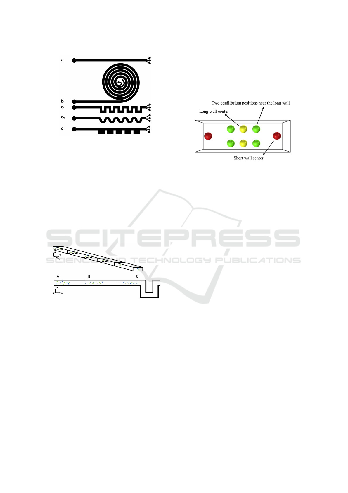
Figure 2: Typical shapes of channels used in inertial mi-
crofluidics (a) straight (b) spiral (c
1
) square serpentine (c
2
)
curved serpentine and (d) CEA channels. Large black cir-
cles represent inflow of the suspension and several smaller
circles represent outflow with separated particles.
Although we focus on serpentine channels, we
briefly sum up the results concerning stabilized posi-
tions of particles in straight channels with rectangular
crossection. We need this, because as can be seen in
Figure 2 (c
1
) and in close detail in Figure 3, the first
part of the channel is often straight and the particles
tend to focus before entering the serpentine part. This
must be taken into account when seeding the particles
or cells at the inflow of the serpentine channel in the
simulation.
Figure 3: Focusing of particles before entering the serpen-
tine part of the channel. Blue particles are in the upper part
and the green particles in the lower part of the channel. Sec-
tor A - particles are distributed across the whole cross sec-
tion coming from the inlet. Sector B - particles are being
focused. Sector C - before entering the serpentines, the par-
ticles are focused in two (or four) positions.
The thorough numerical analysis confirmed by
comparison with experimental results has been pro-
vided by (Mashhadian and Shamloo, 2019). The au-
thors show a detailed analysis of stabilized positions
of particles various sizes in straight rectangular chan-
nels depending on the channel Reynolds number and
the channel aspect ratio. They show (see Figure 4)
different stabilized positions in a rectangular cross
section: center of short walls (red), center of long
walls (yellow) and two other positions near long wall
(green). Therefore we are able to derive stable posi-
tions at the entrance of our serpentine channels. This
is done later in Section 3.4.
We must emphasize that straight channels are not
suitable for separating particles of different sizes due
to the similarity of focused positions for particles of
different sizes.
Figure 4: Different stabilized positions in a rectangular
cross-section. Reprinted from (Mashhadian and Shamloo,
2019) with permissions.
3 MODEL AND
COMPUTATIONAL SETUP
3.1 Numerical Model
We use well-established computational model of fluid
and the immersed particles or cells. Here, the liquid
is calculated with the lattice-Boltzmann (LB) method
(Arnold et al., 2013). The cells are taken into ac-
count as immersed objects with fully 3D discretiza-
tion using tetrahedrons that cover whole inner space
inside the sphere. At the edges of the small tetrahe-
drons, fairly rigid springs are set so that the object
almost does not undergo any deformation during the
flow. Detailed description of the underlying models
are available in (Jan
ˇ
cigov
´
a et al., 2020; Jancigova and
Tothova, 2014; Bachrat
´
y et al., 2018). The valida-
tion and verification of the computational models has
been provided in (Jan
ˇ
cigov
´
a et al., 2020; Jan
ˇ
cigov
´
a,
2020; Tothova et al., 2015). For all simulations we
used tetrahedral meshes with edges of sizes approxi-
mately 0.4 µm.
3.2 Channel Geometry
Our aim is to simulate rectangular serpentine chan-
nels as depicted in Figure 2 (c
1
). In the figure, there
are only six S-shaped repeating sections displayed,
however in practise, there are more sections needed
to obtain desired focusing positions. Together with
long straight channels before and after serpentines,
the whole channel is too large to model at whole.
Therefore we will model only one repeating section
BIOINFORMATICS 2023 - 14th International Conference on Bioinformatics Models, Methods and Algorithms
286
(between the dashed seeding and reseeding line in
Figure 5) enlarged by fluid evolution sections before
and after, with periodical boundary conditions at the
inflow and outflow. This way we ensure that the fluid
is fully evolved at the seeding and reseeding lines. Pe-
riodicity of the middle section allows to reseed the
cells back to the seeding line as soon as they reach
the reseeding line. Their relative position at the cross
section is preserved during the reseeding, as well as
their velocity.
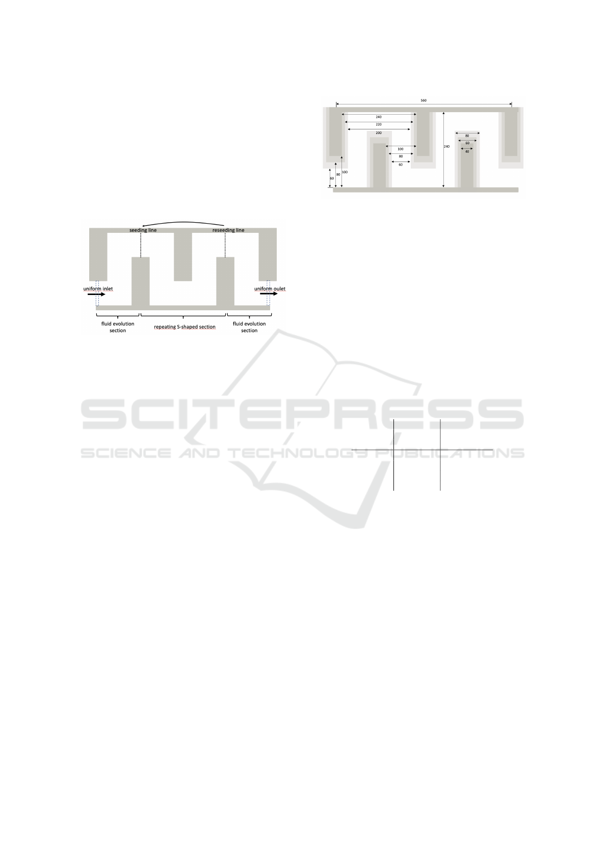
Figure 5: Simulation box for the case of the cross section
with dimensions 80 × 40µm. One repeating S-shaped sec-
tions enlarged by two fluid evolution sections.
After initial seeding of particles on the seeding
line in the channel at the beginning of the flow, we
watched the positions of the origins of the particles
during the flow. When the particles have arrived to the
reseeding line, we reseeded them back to the seeding
line with the new coordinates of the particle origins
and we have continued the watching of these origins
coordinates. With this kind of reseeding by repeating
the S-shaped section, as you can see on the picture
in Figure 5, we have done a simulation of periodical
flow without real construction of the real microchan-
nel. As a result we get the trajectories (from the origin
coordinates during the flow process). In Section 4 you
can see analyses.
Since we study three different cross sections, the
respective dimensions of the channels are different for
all three cases. The respective dimensions of channels
are depicted in Figure 6. Note that the lengths of the
channel along the axial center of the channel are pre-
served.
3.3 Geometry and Fluid Set-up
To create a specific geometry as a serpentine channel,
we need to define boundaries in the simulation box.
This is done using geometrical shapes of rhomboids
in the open-source scientific simulation package
ESPResSo with PyOIF module (Jan
ˇ
cigov
´
a et al.,
2020).
To let the static fluid at the beginning of the simu-
Figure 6: Dimensions of three different geometries in µm.
The darkest boundaries represent 100 × 32µm, the medium
dark represent 80 × 40µm and the brightest represent 60 ×
52µm cross section.
lation fully evolve, we simulate 500µs without the
particles. The uniform boundary conditions at inlet
and outlet define the average velocity in the channel
which is proportional to the volumetric flow rate.
This can be done in PyOIF using a special velocity
boundary (visualized in Figure 5 by dashed rectan-
gles), with predefined constant values of velocity
field at the boundary points.
Specific values of the inlet conditions and the cor-
responding flow rates are presented in Table 1.
Table 1: Fluid parameters in 80× 40µm rectangular channel.
Values in channels with other cross sections are similar.
Average Reynolds Volumetric
velocity number flow
[µm/µs] [ - ] [mL/min]
0.18 19.2 0.035
0.35 37.3 0.062
0.45 48 0.086
0.6 64 0.115
We are interested in studying the flows in phys-
ically relevant cases. We consider fluid with density
and viscosity similar to physiological solutions or wa-
ter being 1000kg/m
3
and 10
−3
Pa.s. In inertial mi-
crofluidics, the relevant ranges for the Reynolds num-
ber are up to 100 (Ying and Lina, 2020). We consider
four different average velocities up to 0.6m/s in the
channel so that Reynolds number varies up to 64. For
maximal velocity for evaluation of Reynolds number
in (5) we take the double of the average velocity. With
cross sectional area of around 3100µm
2
it accounts for
the volumetric flow rate being up to 0.115mL/min.
3.4 Particle Seeding
Since in various straight channels with a rectangular
cross-section the particles in the flow settle in two sta-
ble positions over time, we also placed the particles in
the running flow of the simulation in close neighbour-
hood of two concrete positions. We wanted the place-
Computational Study of Particle Separation Based on Inertial Effects in Rectangular Serpentine Channels with Different Aspect Ratios
287
ment randomly, so we used the normal distribution for
seeding particles around this two positions. As you
can see in Figure 7, we have three different geome-
tries with particles seeded at the beginning of every
simulation by normal distribution with same standard
deviation, which we chose around the two positions.
In order to assure the reproducibility of the experi-
ments we used the same random seeding for 5µm par-
ticles and 10µm particles.
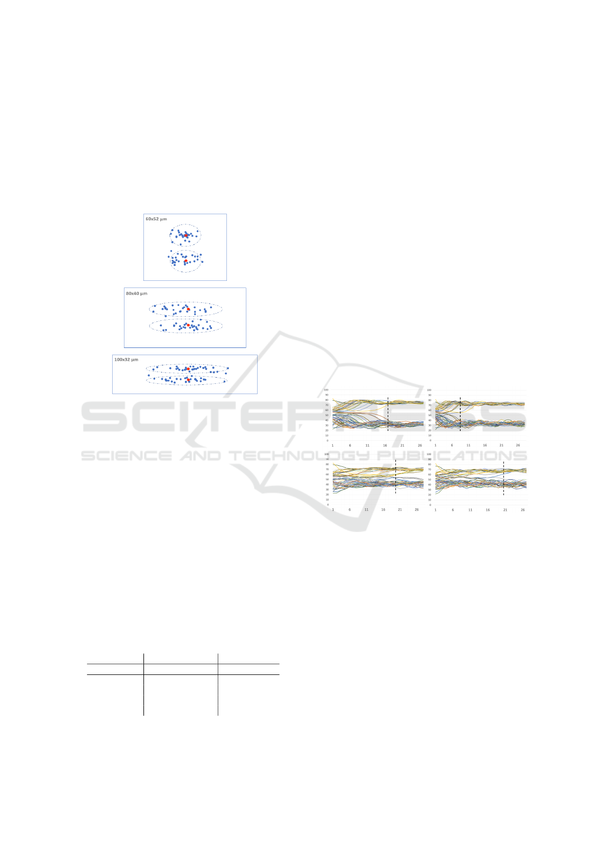
Figure 7: Three different cross sections of rectangular chan-
nels with particle seeding. Centers of the particles (blue
dots) are depicted distributed by normal distribution around
stable positions of straight channels (red dots).
4 COMPUTATIONAL RESULTS
Our aim is to examine how the stable positions within
several cross-sections are dependent on geometric pa-
rameters of the channel. We compared three differ-
ent cross-sections in square wave channel and in each
cross section, we modified average fluid velocity and
the size of the particles. The other parameters were
kept constant. In Table 2 we present values of the
parameters that were examined. Together we run 24
simulations.
Table 2: Overview of three varying parameters: size, veloc-
ity and cross section. Simulations have been performed for
all 24 combinations.
Particle size Average velocity Cross section
µm µm/µs µm × µm
5 0.18 60 × 52
10 0.35 80 × 40
0.45 100 × 32
0.6
4.1 Focusing Length
First we need to determine the focusing length of the
channel. We tracked the trajectories of the cells un-
til the particles reach stable region. Each of the 24
simulations was run such that at least 28 passes of the
particles through the repeating S-section occurred.
In Figure 8 we see four 100 × 32µm cases: 5 and
10µm particles each for two different Reynolds num-
bers. Horizontal axis shows the number of passes
through the repeating S-shaped section and vertical
axis shows the particle position along the width of
the channel ranging from 0 to 100µm in these cases.
We can clearly see when the particles start stabilize
and we can define the minimal focusing length. In
the figure we show trajectories for only two values of
Reynolds number, however, taking account of all four
values we arrive at the focusing length for cross sec-
tion 100 × 32µm to be 19 passes. Analogous we de-
duce 15 passes and 18 passes to be focusing lengths
for 60 × 52µm and 80 × 40µm, respectively.
After determining the focusing length, we further
work with positions of particles across the channel
width at the moment of passing this focusing length.
Figure 8: Trajectories of 5µm particles (top figures) and
10µm particles (bottom figures) in channel with 100× 32µm
cross section for Reynolds number 37.3 (figures on the left)
and 64 (figures on the right). Black vertical lines indicate
minimal focusing length. Horizontal axis gives number of
passes through the repeating S-section. Vertical axis gives
particle position across the width of the channel.
4.2 Particle Separation
The three different geometries achieve different fo-
cusing performance for small and large particles. All
three geometries have different focusing length but
this is not a limitation: Once we pick the desired ge-
ometry, the channel length will be adapted accord-
ingly. The particle focusing positions are either dis-
tinct and separated to more positions or focused along
the center of the channel width. In some cases we
could separate them, but in some cases they are fully
BIOINFORMATICS 2023 - 14th International Conference on Bioinformatics Models, Methods and Algorithms
288
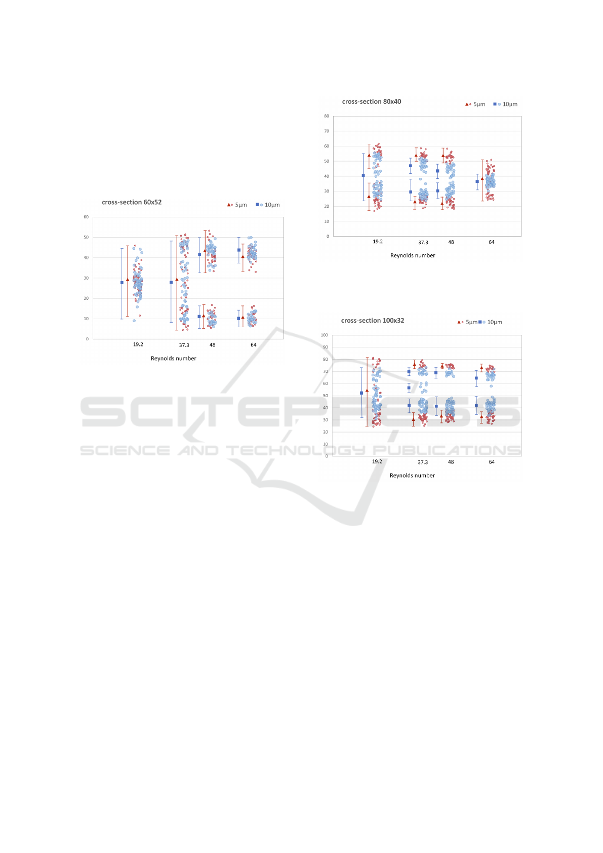
overlapping. The results are depicted in Figures 9 –
11.
For the case of 60 × 52 rectangular channel we
assigned the smallest focusing length. The particles
were focused already after 15 times of S-shaped sec-
tions repeating. However we get almost fully overlap-
ping distributions of 5µm and 10µm particles across
the channel width.
Figure 9: Particle focusing in 60 × 52µm cross section for
various Reynolds numbers. Focusing length was 15 passes
of the repeating S-section. Vertical axis gives particle posi-
tion in [µm] across the width of the channel.
In 80 × 40 rectangular channel we can stop the
simulations after 18 passes of S-shaped section. We
can observe the best focusing performance for the
Reynolds number between 32 and 50. The 5µm parti-
cles are separated in two positions across the channel
width. The 10µm particles are focused along the cen-
ter of the channel width, and the width of particle dis-
tribution gradually decreases to a single stable focus-
ing line with higher Reynolds number. At Reynolds
numbers 37.3 and 48 we can see in Figure 10 slightly
overlapping of focusing sections for 5µm and 10µm
particles which may result in non-perfect separation.
This contributes to the best possibility of separating
particles of two sizes. For the highest Reynolds num-
ber we can see overlapping of these two different par-
ticle sizes and it is not able to separate them.
For the case of 100 × 32 rectangular channel we
needed 19 passes of the S-shaped section to get the
best focusing of the particles. The 5µm particles have
the best particle separation possibility. The focusing
positions are fully distinct and we get the biggest gap
between them as you can see in Figure 11, more than
30µm with Reynolds numbers 37,3 and 48. In this
case, we have larger range of Reynolds numbers for
separation.
Figure 10: Particle focusing in 80 × 40µm cross section for
various Reynolds numbers. Focusing length was 18 passes
of the repeating S-section. Vertical axis gives particle posi-
tion in [µm] across the width of the channel.
Figure 11: Particle focusing in 100× 32µm cross section for
various Reynolds number. Focusing length was 19 passes of
the repeating S-section. Vertical axis gives particle position
in [µm] across the width of the channel.
5 DISCUSSION
First of all we have very good agreement with results
presented in (Ying and Lina, 2020) for the cross sec-
tion 80 × 40µm. This validates our computational ap-
proach.
To compare various cross sections, we can draw
several conclusions.
First observation is that the 60 × 52µm cross sec-
tion is not suitable for particle separation. Although
the particles focused after the shortest distance, the fo-
cused position of particles overlap for both analyzed
sizes.
As previous results from (Ying and Lina, 2020)
suggested, a good candidate for separation is the
Computational Study of Particle Separation Based on Inertial Effects in Rectangular Serpentine Channels with Different Aspect Ratios
289

channel with 80 × 40µm cross section. This was
confirmed by our computations and indeed, with
Reynolds numbers 37 and 48 we get the possibility for
particle separation. In this cross section, with higher
Reynolds numbers we loose the possibility for sepa-
ration because particles of both sizes drift towards the
center of the channel. 10µm particles focus in nar-
rower strip (width 10µm) while 5µm particles focus
in wider strip (width 30µm). However, the two strips
completely overlap.
The results for cross section 100 × 32µm give
larger possibility for separation. Not only the offer
separation for Reynolds numbers 37 and 48 but also
at 64 we still have distinctive focusing position for
particles of different sizes. Again, with increasing
flow velocity we see tendency of particles to focus
closer to the channel center, however this tendency is
much weaker than for 80× 40µm cross section and the
particles still leave a particle-free strip in the middle
of the channel.This results have two important conse-
quences:
• Higher throughput is possible due to large
Reynolds number and thus larger fluid velocity.
• Separation of even large particles is possible.
Since 5µm and 10µm particles leave a particle-free
strip in the middle of the channel, it may be possi-
ble to separate a third size of particles that would
focus right in that strip.
This paper is expected to be instructive for opti-
mization of inertial microchannel structures and for
next bio-related studies and applications, for example
blood cell separation in medicine.
ACKNOWLEDGEMENTS
This publication has been produced with the support
of the Integrated Infrastructure Operational Program
for the project: Systemic Public Research Infrastruc-
ture - Biobank for Cancer and Rare diseases, ITMS:
313011AFG5, co-financed by the European Regional
Development Fund.
REFERENCES
Arnold, A., Lenz, O., Kesselheim, S., Weeber, R., Fahren-
berger, F., Roehm, D., Ko
ˇ
sovan, P., and Holm, C.
(2013). ESPResSo 3.1: Molecular dynamics soft-
ware for coarse-grained models. In Meshfree Methods
for Partial Differential Equations VI, Lecture notes in
computational science and engineering, pages 1–23.
Springer Berlin Heidelberg, Berlin, Heidelberg.
Bachrat
´
y, H., Bachrat
´
a, K., Chovanec, M., Kaj
´
anek, F.,
Smie
ˇ
skov
´
a, M., and Slav
´
ık, M. (2018). Simulation
of blood flow in microfluidic devices for analysing of
video from real experiments. In Bioinformatics and
Biomedical Engineering, Lecture notes in computer
science, pages 279–289. Springer International Pub-
lishing, Cham.
Cetin, B. and Li, D. (2011). Dielectrophoresis in microflu-
idics technology. Electrophoresis, 32(18):2410–2427.
Chun, B. and Ladd, A. J. C. (2006). Inertial migration of
neutrally buoyant particles in a square duct: An in-
vestigation of multiple equilibrium positions. Phys.
Fluids (1994), 18(3):031704.
Di Carlo, D., Edd, J. F., Humphry, K. J., Stone, H. A., and
Toner, M. (2009). Particle segregation and dynamics
in confined flows. Phys. Rev. Lett., 102(9):094503.
Forbes, T. P. and Forry, S. P. (2012). Microfluidic mag-
netophoretic separations of immunomagnetically la-
beled rare mammalian cells. Lab Chip, 12(8):1471–
1479.
Gossett, D. R., Tse, H. T. K., Lee, S. A., Ying, Y., Lindgren,
A. G., Yang, O. O., Rao, J., Clark, A. T., and Di Carlo,
D. (2012). Hydrodynamic stretching of single cells for
large population mechanical phenotyping. Proc. Natl.
Acad. Sci. U. S. A., 109(20):7630–7635.
Hood, K., Lee, S., and Roper, M. (2015). Inertial migration
of a rigid sphere in three-dimensional poiseuille flow.
J. Fluid Mech., 765:452–479.
Jan
ˇ
cigov
´
a, I. (2020). Computational modeling of blood
flow with rare cell in a microbifurcation. In Lec-
ture Notes in Computational Vision and Biomechan-
ics, Lecture notes in computational vision and biome-
chanics, pages 518–525. Springer International Pub-
lishing, Cham.
Jan
ˇ
cigov
´
a, I., Koval
ˇ
c
´
ıkov
´
a, K., Bohinikov
´
a, A., and
Cimr
´
ak, I. (2020). Spring-network model of red blood
cell: From membrane mechanics to validation. Int. J.
Numer. Methods Fluids, 92(10):1368–1393.
Jancigova, I. and Tothova, R. (2014). Scalability of forces in
mesh-based models of elastic objects. In 2014 ELEK-
TRO. IEEE.
Jan
ˇ
cigov
´
a, I., Koval
ˇ
c
´
ıkov
´
a, K., Weeber, R., and Cimr
´
ak, I.
(2020). Pyoif: Computational tool for modelling of
multi-cell flows in complex geometries. PLoS Com-
putational Biology, 16:e1008249.
Jiang, D., Tang, W., Xiang, N., and Ni, Z. (2016). Nu-
merical simulation of particle focusing in a symmetri-
cal serpentine microchannel. RSC Adv., 6(62):57647–
57657.
Li, S., Ding, X., Guo, F., Chen, Y., Lapsley, M. I., Lin, S.-
C. S., Wang, L., McCoy, J. P., Cameron, C. E., and
Huang, T. J. (2013). An on-chip, multichannel droplet
sorter using standing surface acoustic waves. Anal.
Chem., 85(11):5468–5474.
Martel, J. M. and Toner, M. (2014). Inertial focusing in
microfluidics. Annu. Rev. Biomed. Eng., 16(1):371–
396.
Mashhadian, A. and Shamloo, A. (2019). Inertial microflu-
idics: A method for fast prediction of focusing pattern
BIOINFORMATICS 2023 - 14th International Conference on Bioinformatics Models, Methods and Algorithms
290

of particles in the cross section of the channel. Anal.
Chim. Acta, 1083:137–149.
Matas, J.-P., Morris, J. F., and Guazzelli,
´
E. (2009). Lateral
force on a rigid sphere in large-inertia laminar pipe
flow. J. Fluid Mech., 621:59–67.
McLaughlin, J. B. (1993). The lift on a small sphere in
wall-bounded linear shear flows. J. Fluid Mech., 246(-
1):249–265.
Ookawara, S., Higashi, R., Street, D., and Ogawa, K.
(2004). Feasibility study on concentration of slurry
and classification of contained particles by microchan-
nel. Chem. Eng. J., 101(1-3):171–178.
Rasooli, R. and C¸ etin, B. (2018). Assessment of lagrangian
modeling of particle motion in a spiral microchan-
nel for inertial microfluidics. Micromachines (Basel),
9(9).
Segr
´
e, G. and Silberberg, A. (1961). Radial particle dis-
placements in poiseuille flow of suspensions. Nature,
189(4760):209–210.
Tanaka, T., Ishikawa, T., Numayama-Tsuruta, K., Imai, Y.,
Ueno, H., Matsuki, N., and Yamaguchi, T. (2012).
Separation of cancer cells from a red blood cell sus-
pension using inertial force. Lab Chip, 12(21):4336–
4343.
Tothova, R., Jancigova, I., and Busik, M. (2015). Calibra-
tion of elastic coefficients for spring-network model
of red blood cell. In 2015 International Conference
on Information and Digital Technologies. IEEE.
Ying, Y. and Lina, Y. (2020). Inertial focusing and separa-
tion of particles in similar curved channels. Scientific
reports, natureresearch, 391:123570.
Computational Study of Particle Separation Based on Inertial Effects in Rectangular Serpentine Channels with Different Aspect Ratios
291
