
Automatic Robotic Arm Calibration for the Integrity Test of Voting
Machines in the Brazillian 2022’s Election Context
Marcondes R. da Silva J
´
unior
1 a
, Jonas Ferreira Silva
1 b
and Jo
˜
ao Marcelo Teixeira
2 c
1
Informatics Center, Universidade Federal de Pernambuco, Recife, Brazil
2
Electronics and Systems Department, Universidade Federal de Pernambuco, Recife, Brazil
Keywords:
Robot Manipulation, Computer Vision, RGB-D Camera, Brazilian 2022’s Election, Integrity Testing.
Abstract:
The Brazilian electoral system uses the electronic ballot box to increase the security of the vote and the speed
of counting the votes. It is subjected to several security tests, and the one that has the most human interaction
and personnel involved is the integrity test. Our macro project proposed a solution to optimize the testing
process and reduce the amount of human beings involved, using a robotic arm with the aid of computer vision
to optimize the personal demand from 8 people to 2. However, in order to use the robot, technical knowledge
was still required, and it could not be used by any user, as it was necessary to manually map the keys to the
places where the robotic arm would press to perform the test. We present a solution for automatically mapping
a workspace to a robotic arm. Using an RGB-D camera and computer vision techniques with deep learning,
we can move the robotic arm with 6 Degrees of Freedom (DoF) through Cartesian actions within a workspace.
For this, we use a YOLO network, mapping of a robot workspace, and a correlation of 3D points from the
camera to the robot workspace coordinates. Based on the tests carried out, the results show that we were able
to map the points of interest with high precision and trace a path plan for the robot to reach them. The solution
was then applied in a real test scenario during the first round of Brazillian elections of 2022, and the obtained
results were compatible to the conventional non-assisted approach.
1 INTRODUCTION
The Brazilian electoral system began its computeriza-
tion process in 1995, when the TSE started the Elec-
tronic Ballot Box project. The old method of vot-
ing using paper ballots, which was slow and suscep-
tible to fraud, gave way to electronic equipment that
brought a greater degree of transparency and security
to the process of voting and counting the votes. In
1996, in municipal elections, 57 cities had their first
contact with the electronic voting machine, counting
the votes of more than 32 million Brazilians. After
that, in the 2000 elections, Brazil held its first com-
pletely computerized election (Court, 2021).
Currently, in order to serve the 147,918,438 peo-
ple eligible to vote, the holding of elections has a high
demand for resources, including logistics, personnel,
costs and so on. It covers 5,568 municipalities around
the country and 483,665 polling stations. Therefore,
a
https://orcid.org/0000-0003-0359-6113
b
https://orcid.org/0000-0002-2277-132X
c
https://orcid.org/0000-0001-7180-512X
the electronic voting system facilitates the electoral
process by providing more efficient mechanisms for
transporting and counting votes (Ferr
˜
ao et al., 2019)
(Pinto et al., 2004).
The electronic voting machine is an embedded
system used in elections, consisting of two terminals:
the polling station terminal and the voter terminal.
The first consists of a numeric keypad, an LCD dis-
play and a biometric reader, where the voter is identi-
fied and the release of the vote at the voter’s terminal
is performed. The second is composed of a numeric
keypad and an LED screen, on which the votes are
recorded.
Despite its advantages, the technology of elec-
tronic voting machines is a recurrent target of criti-
cism and attacks. Many people do not trust the elec-
tronic process and suggest the evolution of the system
or the return of the traditional model, based exclu-
sively on paper (VOGEL, 2006).
There are also arguments about the lack of print-
ing of the vote and the difficulty of political parties
and civil organizations to monitor and audit the stages
of voting, counting and totaling. In this sense, the
Silva Júnior, M., Silva, J. and Teixeira, J.
Automatic Robotic Arm Calibration for the Integrity Test of Voting Machines in the Brazillian 2022’s Election Context.
DOI: 10.5220/0011787400003417
In Proceedings of the 18th International Joint Conference on Computer Vision, Imaging and Computer Graphics Theory and Applications (VISIGRAPP 2023) - Volume 4: VISAPP, pages
687-694
ISBN: 978-989-758-634-7; ISSN: 2184-4321
Copyright
c
2023 by SCITEPRESS – Science and Technology Publications, Lda. Under CC license (CC BY-NC-ND 4.0)
687

Brazilian electoral system has constant challenges re-
lated to the transparency, reliability and security of the
process as a whole. Therefore, there are several ways
to audit and test the polls.
As mentioned before, tests and inspections are
carried out at least every 3 months in the Brazilian
electronic voting machines, in order to ensure their in-
tegrity. One of the main tests carried out in this regard
is the Electronic Ballot Box Integrity Test, which is a
parallel vote to the official one, which aims to demon-
strate the proper functioning of the equipment and the
security of the Electronic Ballot Box. This process
starts the day before the elections; in which 641 elec-
tronic voting machines, randomly selected from ap-
proximately 500,000 voting machines, are removed
from their polling stations and replaced by new ones.
The selected voting machines are then taken to the
place where the Integrity Test will take place. In or-
der to carry out this voting equivalent to the official
vote, the process begins on the eve of the elections,
when a public ceremony takes place for the draw-
ing of the voting machines that will participate in the
tests. Then, the randomly selected electronic voting
machines are transported from their original sections
to the place where the integrity test is carried out, and
the entire audit process is monitored by cameras. In
parallel with the draw, to simulate voters, voting bal-
lots are filled out by students from the public educa-
tion network, representatives of political parties and
coalitions, which are deposited in sealed canvas urns.
On election day, the integrity test starts at the same
time as the official voting and the first procedure is
to print the zero, which is an extract that proves the
absence of votes counted in the electronic voting ma-
chine. Then, all votes from the ballots that were filled
in earlier are entered, one by one, in a parallel sys-
tem. At the end of the day, a Ballot Box Report (BU)
is printed and the auxiliary system also issues a bul-
letin. This way, both countings are compared in order
to verify if the electronic voting machine worked nor-
mally, verifying that the votes received are in accor-
dance with the votes counted.
Currently, the Integrity Test process has the par-
ticipation of 6 (six) to 8 (eight) people per Electronic
Ballot Box to be audited. To increase productivity
and reduce the chance of human error involved in
the testing process, a solution for test automation was
devised: this alternative solution uses a robotic arm
guided by computer vision and 1 (one) human being.
However, even with the automation of the process,
it was still necessary to map the robot’s position man-
ually, so the main focus of this work is to present a
process for the automatic mapping of the keys of the
electronic voting machine as a whole. We use a robot
with Cartesian motion support, enabling the mapping
of robot coordinates to the RGB-D camera coupled on
it using computer vision techniques and deep learn-
ing, so that the machine understands what it is seeing.
The results obtained by this work were considered
satisfactory, where our macro project, which is the
”automation of the audit of the functioning of elec-
tronic voting machines in Brazilian elections” won a
technological innovation award in the Brazilian judi-
ciary and was presented to the minister of the federal
supreme court( STF), who at the time was the presi-
dent of the Superior Electoral Court (TSE). In addi-
tion, as a technical result, it was possible to detect,
track and map all the keys on the Brazilian electronic
voting machine.
The present work is structured as follows. Sec-
tion 2 presents the background, which shows what
was used to create our solution. Section 3 describes
the methodology used to create our solution. Section
4 describes the tests and results, while section 5 con-
cludes the work and points future work directions.
2 RELATED WORKS
Garcia et al. (Garcia et al., 2013) used a mapping
approach very similar to the one of this work. They
also used four target points to guide the robotic arm
in tasks of interacting or manipulating objects within
the created workspace. The depth information in the
image improves the accuracy of the trajectory calcu-
lation.
Singh, Rakesh et al. (Singh and Kotecha, 2021)
do a work focused on the optimization of the SLAM
algorithm, the authors propose to use the deep learn-
ing technique to improve the SLAM algorithm so that
it is able to differentiate between static and dynamic
objects.
Viturino et al.(Viturino et al., 2021) used an in-
stance segmentation method (Mask R-CNN), a point
cloud collision verification system and a path plan-
ning technique with orientation control based on the
Adaptive Artificial Potential Field algorithm to detect
and grasp objects using a robotic arm with 6DoF.
3 BACKGROUND
In this section, we will present the main concepts
that were underneath the proposed solution. We start
by providing some background related to object de-
tection and specifically YOLO’s neural network, and
end the section talking about the benefits of using an
VISAPP 2023 - 18th International Conference on Computer Vision Theory and Applications
688

RGB-D camera for robotic arm placement and manip-
ulation activities.
3.1 Object Detection
Detection of objects in images is a computer vision
task that aims to locate instances of objects of a cer-
tain class in a scanned image. An object detection
system of a specific class can be defined as a function
f, which maps a digital image I in the set of locations
B, given the model W. Thus, we have:
B = f(I, W)
The location of an object can be defined in terms
of a bounding box, a rectangle aligned to the x and y
axes of the image that describes the object. A bound-
ing box is defined by a vector b ∈ R4, which indicates
the upper left and lower right coordinates of the rect-
angle. Each location detected by the system is asso-
ciated with a value c ∈ [0 , 1], which indicates the
reliability of the system that the bounding box cor-
rectly describes an object of the class it is desired to
detect.
During training of an object detection system, a
criterion must be defined to identify whether a loca-
tion detected by the system corresponds to an object
in the processed image. If the set of examples is anno-
tated with the bounding boxes of the objects contained
in their images, the detected locations are compared
to each of the annotations, according to a similarity
metric.
If a detection is compared to reference locations
and does not obtain a minimum similarity value, it is
considered that the location does not correspond to an
object of the detected class, that is, a false detection
has occurred. If more than one detection obtains a
similarity above the minimum value in relation to the
same reference, repeated detections are considered to
have occurred. If no detection obtains minimal sim-
ilarity with respect to a specific reference, it is said
that the detection has failed.
3.1.1 YOLO
YOLO (You Only Look Once) is a computer vision
technique used to detect objects in real time, accord-
ing to Redmon et al. (2016)(Joseph Redmon and
Farhadi, 2016) the YOLO method reformulates the
detection of objects by transforming it into a regres-
sion problem, starting only from the pixels of an im-
age, which results in the probabilities by class, in the
coordinates and in the dimensions of the predictions
that delimit the objects. In addition to being sim-
ple, since it uses an end-to-end approach with a sin-
gle convolutional network, it also presents competi-
tive performance as a function of time. Unlike other
object detection methods based on convolutional net-
works, YOLO only needs a propagation of the input
through the network to generate predictions, present-
ing performance compatible with real-time object de-
tection methods, maintaining predictive accuracy.
For the fourth version, the au-
thors(BOCHKOVSKIY et al., 2020) proposed
to perform an ideal balance between the input
network resolution, the convolutional layer number,
the parameter number and the number of outputs of
the layer. As a result, the main features that can be
highlighted in this version are the improvement in
inference speed and accuracy. Another important
feature is the fact that it is more efficient to run on
GPUs, as it has been optimized to use less memory.
Chien-Yao Wan at al.(Wang et al., 2022) as-
sert that YOLOv7 is the fastest and most accurate
real-time object detection model for computer vision
tasks.
YOLOv7, compared to its predecessor and its
base, YOLOv4, provides much improved real-time
object detection accuracy without increasing infer-
ence costs. YOLOv7 can effectively reduce about
40% of the parameters and 50% of the state-of-the-art
real-time object detection computation and achieve
faster inference speed and higher detection accu-
racy.Overall, YOLOv7 provides a faster and stronger
network architecture that provides a more effective
method of resource integration, more accurate object
detection performance, a more robust loss function,
and greater efficiency in labeling and training model.
In the work of Chien-Yao Wang at al.(Wang
et al., 2022) YOLOv7’s performance was evaluated
based on previous versions of YOLO (YOLOv4 and
YOLOv5) and YOLOR as baselines. The mod-
els were trained with the same settings. The new
YOLOv7 shows the best balance between speed and
accuracy compared to high-end object detectors.
3.2 Camera Calibration
When recording an image in a photograph, what an
ordinary still camera basically does is sampling and
geometrically mapping the 3D points of the world
scene onto a 2D image plane. This mapping of the
sampled points is called projection(Hartley and Zis-
serman, 2004). There are several models of cam-
eras that can be used to project images of 3D scenes,
among which there are those that use lenses and those
that do not, with the models without lenses being the
simplest ones.
In principle, to calculate the image projection of
real objects from a 3D world onto a 2D plane, it is
Automatic Robotic Arm Calibration for the Integrity Test of Voting Machines in the Brazillian 2022’s Election Context
689
necessary to define the position of the 3D points of
the objects present in the scene in relation to a com-
mon coordinate system. This generic coordinate sys-
tem is called the world coordinate system, its origin is
at (0, 0, 0) and the location of each object in the scene,
including the camera, can be expressed by three coor-
dinates (Xw,Yw,Zw), as illustrated in Figure 1.
As the image projection of an object does not de-
pend only on its location in the world, but also on the
position of the camera that projects it in relation to the
object itself, it is common to establish an alternative
coordinate system considering the coordinates of the
camera center in relation to the world. This system is
known as the camera coordinate system, whose val-
ues with respect to each axis are given by (Xc,Yc,Zc).
This new system corresponds to the world coordinate
system after undergoing a certain transformation (ro-
tation and translation) that leaves its axes coincident
with the respective axes of the camera coordinate sys-
tem, as shown in Figure 1.
Figure 1: Camera coordinate system obtained from a world
coordinate system transformation.
The rotation and translation that align the two co-
ordinate systems are represented respectively by a ro-
tation matrix R3x3 and a translation vector |R|T|3x3.
In order to simplify the notation, it is common to
use the concatenation of these matrices and represent
them as a single matrix |R|T|3x4. The matrix |R|T|
is known as the matrix of extrinsic camera parameters
(pose matrix or simply pose), because with it it is pos-
sible to know the external parameters of the device,
such as location and inclination. The camera pose ma-
trix corresponds to the transformation needed to take
points from one coordinate system to another. Math-
ematically, transforming any 3D point that is repre-
sented in the world coordinate system to the camera
coordinate system using |R|T| means calculating the
product of this matrix with the 4 x 1 matrix formed by
the homogeneous coordinates of that point:
In the aforementioned equation, [xw, yx, zw, 1] T
is the matrix with the homogeneous coordinates of a
point in the world and [xc, yc, zc] T is the matrix with
the coordinates of the transformed point, that is, in the
coordinate system from the camera.
The rotation matrix R3x3 is obtained through the
matrix product of the rotations on the axes of the
world coordinate system during the transformation,
that is, if this rotation occurs with angles α,β and γ
respectively on the axes Xw, Yw and Zw that same
order, the matrix R can be evaluated as follows:
This rotation can still be represented by a vector
of only three dimensions, whose components corre-
spond to the angles α,β and γ used in calculating R.
These angles are respectively called pitch, yaw and
roll and make up a very used particular case of rota-
tion in Euler angles.
4 METHODOLOGY
This section is dedicated to the presentation of the
proposed solution for automatic mapping. The so-
lution was made for Cartesian movements of 6DoF
robotic arms. The focus of this automatic mapping is
for the robot to be able to track the buttons of the elec-
tronic voting machine in a pre-defined workspace.
To implement the solution, some steps were nec-
essary, namely: creation of the robot workspace, cre-
ation of the dataset, use of the YOLOv7 network, spa-
tial transformation of Cartesian points of the camera
to Cartesian points of the robot and path planning of
robot movements.
4.1 Robotic Arm Workspace
The workspace of a robotic arm is the set of all po-
sitions it can reach. This depends on several factors,
including arm dimensions.
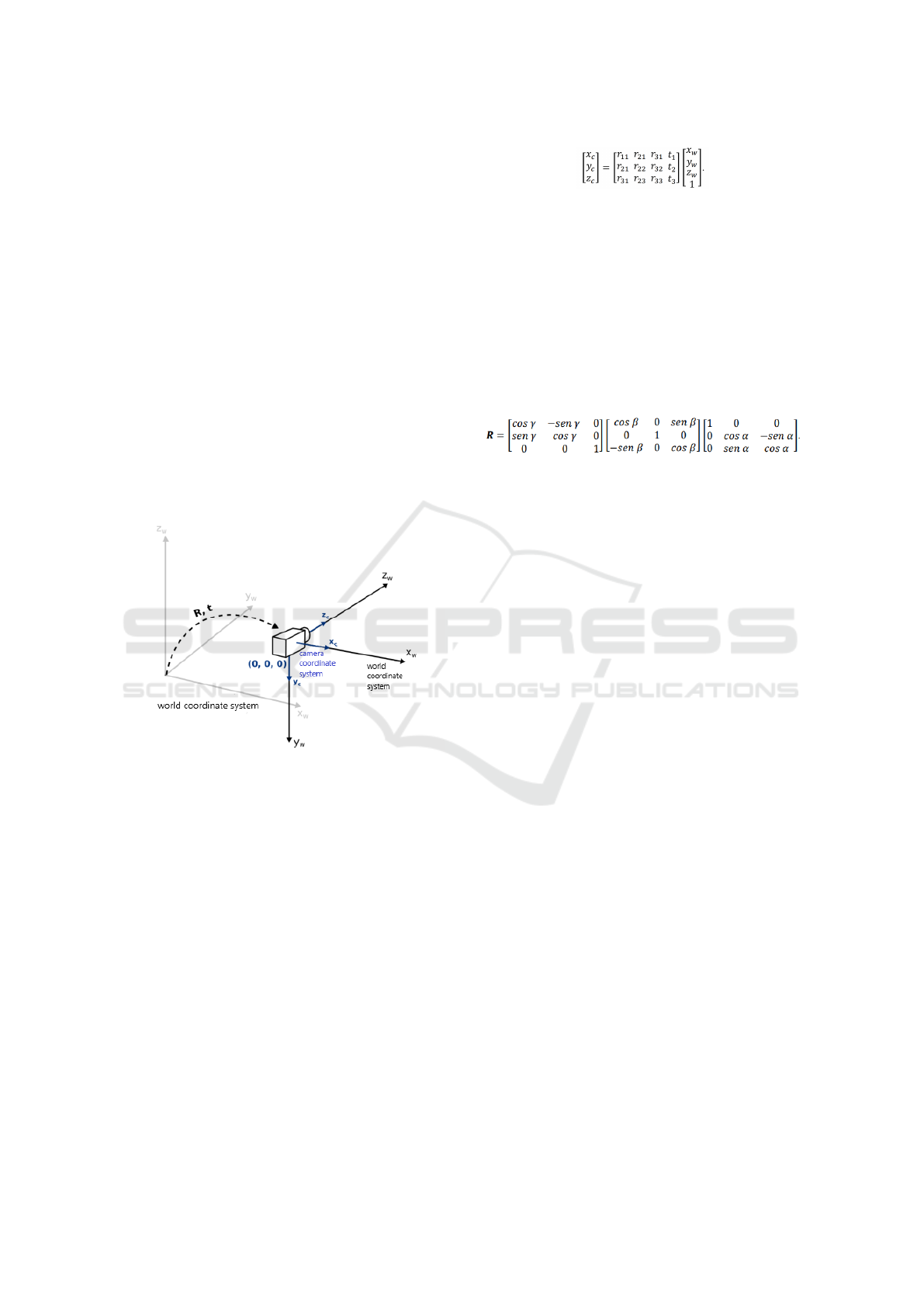
For our work, a “template” was created, shown
in Figure 2, where the electronic voting machine re-
mains in a fixed direction in relation to the robot base,
this was necessary so that the complexity of the solu-
tion was reduced, since with the template, it is pos-
sible to know in which axis of the robot the urn is
located, thus, it is not necessary to track the urn, but
only its buttons.
VISAPP 2023 - 18th International Conference on Computer Vision Theory and Applications
690
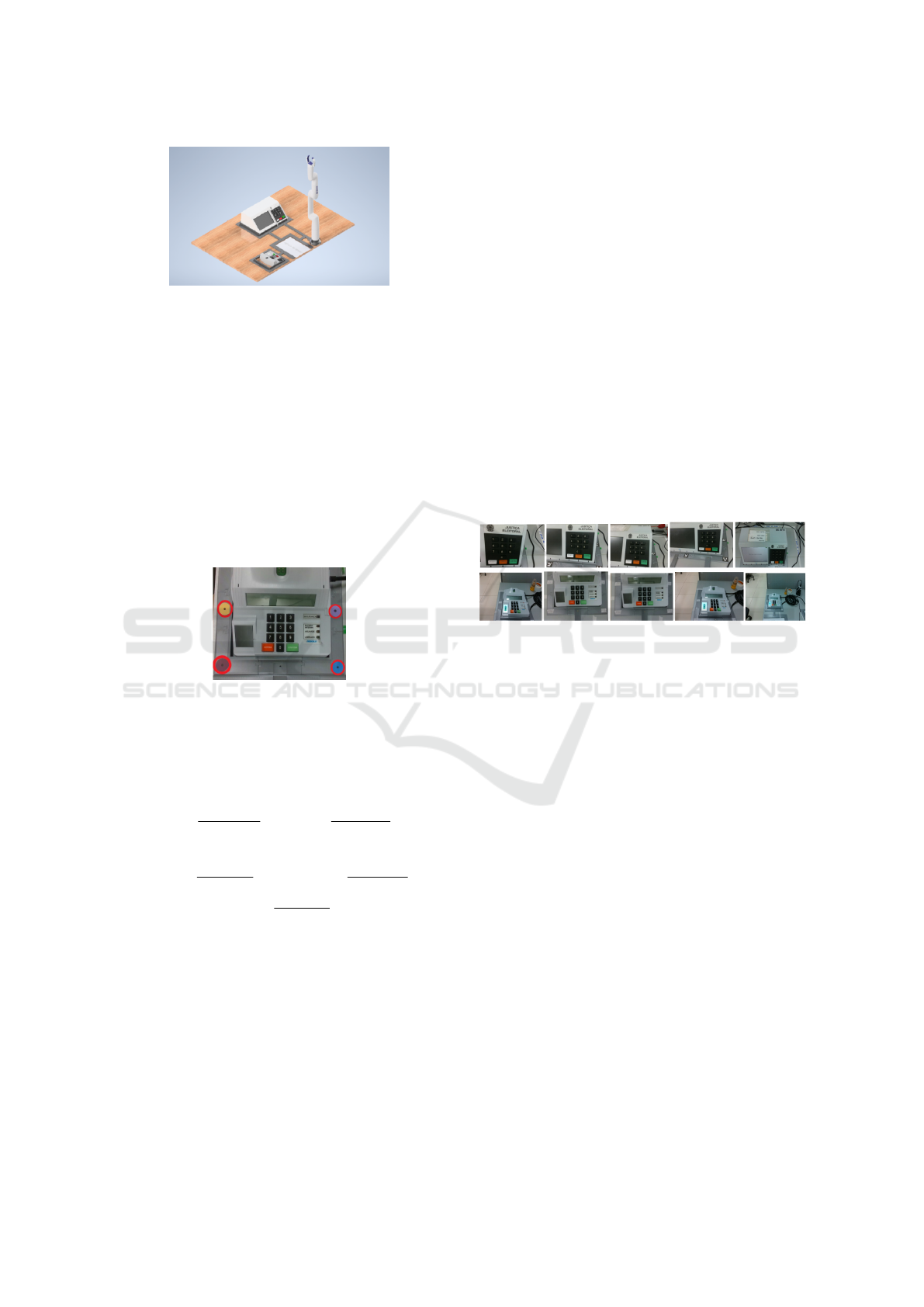
Figure 2: Robot template.
Knowing where the voter terminal and the polling
station terminal would be, the robotic arm was moved
to a position where it would be ”seeing the polling
station terminal”, this way it was possible to save the
cartesian coordinates(x,y,z) and angle position of at-
tack (roll,pitch,yaw) of the robot as “see” position to
start his workspace within our work.
From the “see” position, the robotic arm was taken
manually, using its joystick, to the center of the points
marked in figure 3, thus saving the Cartesian coordi-
nate values (x,y,z) and angle of attack(roll,pitch,yaw)
from each point, so that we could create our robotic
arm workspace.
Figure 3: Robot workspace.
After that we would have 5 points saved, so we
were able to extrapolate a “pivot” position, which
would be an intermediate position for pressing the
keys, where this position was calculated by the ex-
pressions:
X =
(X
min
+X
max
)
2
Y =
(Y
min
+Y
max
)
2
Z = (Z
posSee
+ Z
min
) ∗ 0.40
Roll =
(
∑
allRolls)
5
Pitch =
(
∑
allPitchs)
5
Yaw =
(
∑
allYaws)
5
where Xmin and Xmax would be respectively the
smallest and largest values of x among the 4 points
that were marked in the workspace, Ymin and Ymax
would be the smallest and largest values of Y and
ZposSee and Zmin would be the Z values of the ”see”
position of the robot and the smallest z value among
the 5 points, with that we have the robot workspace
defined.
4.2 Dataset and Markup
For the construction of the dataset, images of the elec-
tronic voting machine were used, obtained through an
Intel Realsense D435 camera, a total of 28,420 im-
ages of the Brazilian electronic voting machine were
obtained, of which 15,300 were from the voter termi-
nal and 13,120 from the polling station terminal.
This way, two sub-datasets were created, where
one contained 984 images of the polling station ter-
minal and the other with 1,147 images of the voter’s
terminal. Derived from the two sub-datasets, images
were separated for training and validation of the net-
work, where 752 were for training and 196 for valida-
tion of the polling station terminal and 917 for train-
ing and 230 for validation of the voter’s terminal.
After splitting the datasets we had an interesting
variety of images for training, as shown in Figure 4.
It was manually checked if it was possible to generate
enough images of the necessary base cases.
Figure 4: Example of dataset images.
With the datasets separated, the images were
marked and the labels were generated for the training
of YOLOv7. This marking was done using the La-
belImg application(Tzutalin, 2015). The buttons that
were found in the image were marked.
4.3 YOLOv7
For the training of YOLOv7, the Google Colab exe-
cution environment was used. The version used for
YOLOv7 was YOLOv7x, which contains 71.3M of
description parameters, with the size of the images for
training and validation being 640 and with a batch-
size of 16, in addition to 200 training periods for the
polling station and 300 training periods for the voter
terminal.
After training, we obtained the confusion matri-
ces, where it was possible to observe that the training
and validation were successful, with 0.99 as the low-
est accuracy value.
Concluding the training, the models were tested
with images that were reserved. 578 images were
used for the polling station terminal and a minimum
confidence level of 0.7 was used. This way, in only
2 images the number 7 was not classified. As for the
voter terminal, 913 images were used for testing using
Automatic Robotic Arm Calibration for the Integrity Test of Voting Machines in the Brazillian 2022’s Election Context
691
a minimum confidence value of 0.7. In this case, ev-
ery button was correctly classified, showing the con-
fidence of the classifier.
4.4 RGB-D Image
At this point, an image is obtained using the Intel Re-
alsense D435 camera. After storage, we followed two
paths: the first path being the detection of the points
that form the robot’s workspace, as shown in figure
5. Having acquired the Cartesian positions(x,y,z), the
robot’s workspace is built, being: (sx, sy, sz), (where
sx is the smallest x value of the points, sy the small-
est y value, and sz being 0, since it is the value at the
camera origin) and (bx,by ,bz) (where bx is the largest
x-value of the points, by the largest y-value, and bz is
the largest z-value among the 4 points in the image).
Figure 5: RGB-D workspace.
The second way is to pass the raw image to the
YOLOv7 detection, where each button is classified
and the value(x,y) of the centroids of each class is re-
turned, along with the class to which it belongs.
Having the return of the centroids of each button,
the depth value is calculated, along with the specific
library of the realsense camera, and the Z value is
saved, along with the x and y values of each centroid
of each button.
In its final part, the values of the camera
workspace and the values of the centroids of each but-
ton are observed, at this point it was necessary to con-
vert the values of x and y of the workspace of the
camera and buttons to the millimeter system, thus the
values of x and y of them were divided by 1000 and
sent to our cartesian transformation module.
4.5 Cartesian Transformation
In this module we have access to the robot and cam-
era workspace that were obtained previously, from the
two workspaces, the following mathematical formula
is used to calculate the x, y and z points of each spe-
cific button:
X
w
= X
w
max
−
(Y
cam
min
−Y
cam
)∗(X
w
max
−X
w
min
)
(Y
cam
min
−Y
cam
max
)
Y
w
=
(X
cam
−X
cam
max
)∗(Y
w
max
−Y
w
min
)
(X
cam
min
−X
cam
max
)
+Y
w
min
Z
w
=
(Z
cam
−Z
cam
max
)∗(Z
w
max
−Z
w
min
)
(Z
cam
min
−Z
cam
max
)
+ Z
cam
min
The robot workspace is defined by (X
w
max
, Y
w
max
,
Z
w
max
), which is the largest (x,y,z) of the workspace
and (X
w
min
, Y
w
min
, Z
w
min
), the smallest (x,y,z) of the
workspace of the robot. With the camera workspace,
we have (X
cam
max
, Y
cam
max
, Z
cam
max
) which is the
largest (x,y,z) of the camera workspace and (X
cam
min
,
Y
cam
min
,Z
cam
min
) which is the smallest (x,y,z), in ad-
dition to the workspaces, we have the values of
(X
cam
,Y
cam
,Z
cam
), which are the values of (x,y,z) of the
button that we are currently calculating. Finally, we
have the values of (X
w
,Y
w
,Z
W
), which are the Carte-
sian values of (x,y,z) that are provided to the robot
as the position of the button. Regarding the values
of the angle of attack (pitch, yaw, roll), which are
necessary for the Cartesian movement of the robot,
the same values of the “pivot” point (shown in the
robotic arm workspace section) were used, which
is calculated as an extrapolation based on the robot
workspace’s Cartesian points. This way, we have the
points (x,y,z,pitch, yaw, roll) of the robot that are
passed to the robot’s movement function to generate
the path planning.
4.6 Path Planning
Initially, attempts were made to directly use the
robot’s Cartesian movement functions to move to the
“see” position, considering it as ”0” position. How-
ever, when directly using the robot’s own Cartesian
movement functions, the movement could not be
completed successfully because the robot’s internal
system could not calculate the path planning to arrive
at the Cartesian point that was passed to it, as shown
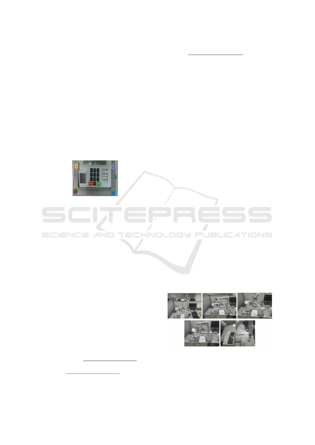
in Figure 14. To get around this problem, the robot
was sent from the “0” position to the “Home” posi-
tion, which is also shown in Figure 6, and then to the
“see” position, to start the mapping.
Figure 6: From right to left and from top to bottom, the po-
sitions: “0”, “Home”, movement attempt to “see” from the
polling station’s terminal, “see” from the polling station’s
terminal, see from the voter’s terminal.
After reaching the “see” position, the image that
VISAPP 2023 - 18th International Conference on Computer Vision Theory and Applications
692
will be used for the automatic mapping is captured.
The process is started using the YOLOv7 detection,
the camera workspace generation, depth inference,
and the module for converting Cartesian points from
the camera to the robot and with that we have our
mapping of pressed keys that is shown in the figure
7, along with the intermediate positions such as the
“pivot”.
Figure 7: a) “pivot” of the voter terminal, b) “pivot” position
of the polling station terminal, c) key “9” pressed, d) key
“1” pressed.
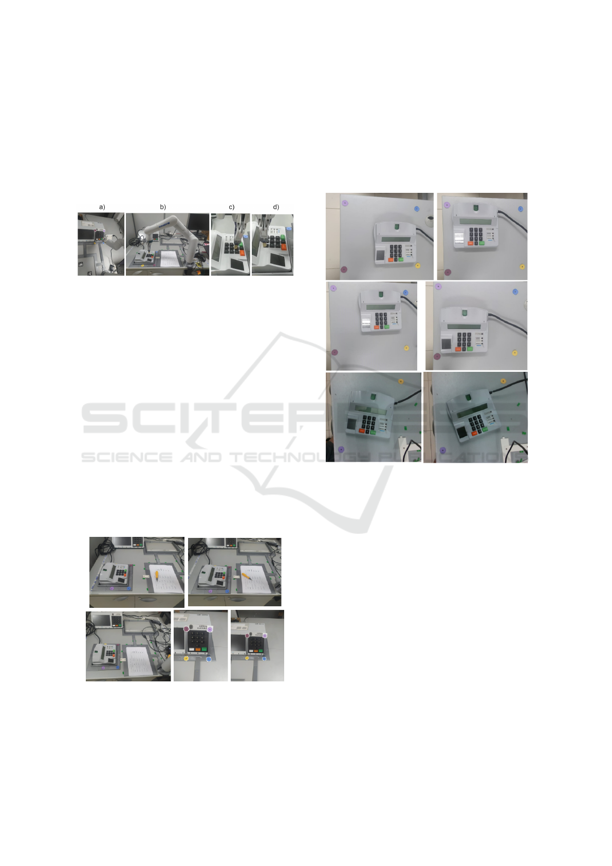
5 TEST AND RESULTS
For the test for our system, two different light con-
figurations were used, with artificial light and with-
out artificial light, in addition to decoupling the tem-
plate from the polling station terminal and the voter
terminal from the robot’s general template and mov-
ing it around the table in 10 different positions. for
the polling station’s terminal and 5 for the voter’s ter-
minal, taking into account locations that the robotic
arm can reach, as shown in figure 8. This way, a robot
workspace was generated for each position that the
poll’s terminal template and the voter terminal is po-
sitioned, besides, for each position we placed the ter-
minals, it was necessary to manually define a position
to “see” this terminal, so that it was possible to map.
Figure 8: Polling station and voter terminal for testing.
In addition to the previous test, another test was
also carried out where we kept the light settings
from the previous test and removed the Polling sta-
tion terminal from the template and placed it inside
a workspace defined on the table itself and moved it
15 times, 5 of which rotated in relation to the robot,
as shown in Figure 9. Unlike the previous test, for
this one it was only necessary to calculate one robot
workspace, one camera workspace and only one “see”
position.
Figure 9: Polling station terminal in a workspace on the
desk itself.
as a result, with what we propose in our work,
we had a 100% success in pressing the keys on the
polling station and on the voter terminal, and it should
be noted that at no time in the tests carried out with the
automatic mapping did the robot pressing two keys at
the same time, or missed the key you should press,
both in the test using the template, and in the test us-
ing a workspace on the table.
With the larger workspace, the desktop, the press
accuracy was higher at the center of the key than when
the workspace is on the template. In addition, with the
workspace on the table, it is only necessary to create
a workspace for the robot and a single “see” position,
reducing even more the work of mapping the keys and
allowing the movement of the desk polling station ter-
minal within the workspace already defined.
also as a result it was possible to use automatic
mapping in the macro project, where we ended up au-
diting two electronic voting machines on the day of
the country’s general election and receiving an inno-
vation award in the Brazilian judiciary.
Automatic Robotic Arm Calibration for the Integrity Test of Voting Machines in the Brazillian 2022’s Election Context
693

6 CONCLUSION AND FUTURE
WORK
In this article we propose a method of detecting the
buttons of the Brazilian electronic voting machine, us-
ing a YOLOv7 network and the automatic mapping
of a robotic arm for pressing the buttons of this elec-
tronic voting machine.
During the project development process, some
problems were encountered, it was noticed by the
team that there were no datasets of the Brazilian bal-
lot box available for use in the work and also that the
robot’s path plan could not calculate some necessary
positions.
To solve the problems, we built the necessary
datasets of the urn for the work in question and cre-
ated intermediate positions with angular movements
so that the robot could move to the Cartesian positions
that were automatically mapped by our solution. The
project is available online.
As future work, the team intends to improve the
automatic mapping method, making new tests, trying
to remove the robot’s general template and replacing
the robot’s path plan with a path plan made by the
Theseus framework (Pineda et al., 2022).
ACKNOWLEDGEMENTS
This work has been supported by the research coop-
eration project between Softex (with funding from
the Ministry of Science, Technology and Innova-
tion—Law 8.248) and CIn-UFPE.
REFERENCES
BOCHKOVSKIY, A., WANG, C.-Y., and LIAO, H.-Y. M.
(2020). Yolov4: Optimal speed and accuracy of ob-
ject detection. Proceedings of the IEEE Conference
on Computer Vision and Pattern Recognition (CVPR).
Court, S. E. (2021). Urna eletr
ˆ
onica 25 anos: lanc¸ado em
1996, equipamento
´
e o protagonista da maior eleic¸
˜
ao
informatizada do mundo.
Ferr
˜
ao, I. G., Chervinski, J. O., da Silva, S. A., Kreutz, D.,
Immich, R., Kepler, F., and da Rosa Righi, R. (2019).
Urnas eletr
ˆ
onicas no brasil: linha do tempo, evoluc¸
˜
ao
e falhas e desafios de seguranc¸a. Revista Brasileira de
Computac¸
˜
ao Aplicada, 11(2):1–12.
Garcia, G. J., Gil, P., Ll
´
acer, D., and Torres, F. (2013). Guid-
ance of robot arms using depth data from rgb-d cam-
era.
Hartley, R. I. and Zisserman, A. (2004). Multiple View Ge-
ometry in Computer Vision. Cambridge University
Press, ISBN: 0521540518, second edition.
Joseph Redmon, Santosh Divvala, R. G. and Farhadi, A.
(2016). You only look once: Unified, real-time ob-
ject detection. Proceedings of the IEEE Conference
on Computer Vision and Pattern Recognition (CVPR).
Pineda, L., Fan, T., Monge, M., Venkataraman, S., Sodhi,
P., Chen, R., Ortiz, J., DeTone, D., Wang, A., Ander-
son, S., Dong, J., Amos, B., and Mukadam, M. (2022).
Theseus: A library for differentiable nonlinear opti-
mization.
Pinto, R. R., Sim
˜
oes, F., and Antunes, P. (2004). Estudo dos
requisitos para um sistema de votac¸
˜
ao electr
´
onica.
Singh, R. and Kotecha, R. (2021). Improving mapping of
static and dynamic objects in slam using deep learn-
ing.
Tzutalin (2015). Labelimg. Free Software: MIT License.
Viturino, C. C. B., de Oliveira, D. M., Conceic¸
˜
ao, A. G. S.,
and Junior, U. (2021). 6d robotic grasping system us-
ing convolutional neural networks and adaptive artifi-
cial potential fields with orientation control. In 2021
Latin American Robotics Symposium (LARS), 2021
Brazilian Symposium on Robotics (SBR), and 2021
Workshop on Robotics in Education (WRE), pages
144–149.
VOGEL, L. H. (2006). A seguranc¸a do voto eletr
ˆ
onico
e as propostas de fiscaliza- c¸
˜
ao da apurac¸
˜
ao pela so-
ciedade.
Wang, C.-Y., Bochkovskiy, A., and Liao, H.-Y. M. (2022).
YOLOv7: Trainable bag-of-freebies sets new state-of-
the-art for real-time object detectors. arXiv preprint
arXiv:2207.02696.
VISAPP 2023 - 18th International Conference on Computer Vision Theory and Applications
694
