
Real-Time Obstacle Detection using a Pillar-based Representation
and a Parallel Architecture on the GPU from LiDAR Measurements
Mircea Paul Muresan
a
, Robert Schlanger
b
, Radu Danescu
c
and Sergiu Nedevschi
d
Computer Science Department, Faculty of Automation and Computer Science, Technical University of Cluj-Napoca,
400114 Cluj-Napoca, Romania
Keywords: 3D Object Detection, Road Surface Estimation, Autonomous Driving, CUDA, Parallel Programming, LiDAR
Point Clouds.
Abstract: In contrast to image-based detection, objects detected from 3D LiDAR data can be localized easier and their
shapes are easier identified by using depth information. However, the 3D LiDAR object detection task is more
difficult due to factors such as the sparsity of the point clouds and highly variable point density. State-of-the-
art learning approaches can offer good results; however, they are limited by the data from the training set.
Simple models work only in some environmental conditions, or with specific object classes, while more
complex models require high running time, increased computing resources and are unsuitable for real-time
applications that have multiple other processing modules. This paper presents a GPU-based approach for
detecting the road surface and objects from 3D LiDAR data in real-time. We first present a parallel working
architecture for processing 3D points. We then describe a novel road surface estimation approach, useful in
separating the ground and object points. Finally, an original object clustering algorithm that is based on pillars
is presented. The proposed solution has been evaluated using the KITTI dataset and has also been tested in
different environments using different LiDAR sensors and computing platforms to verify its robustness.
1 INTRODUCTION
Accurate environment perception is an essential task
for autonomous systems. Currently, the perception
module of intelligent vehicles uses sensors such as
RADARs, LiDARs, and high-definition cameras to
make a virtual representation of the real world
(Muresan et al., 2020). The vehicle then uses the
information from the virtual representation of the
world in subsequent components such as path
planning (Lin et al., 2021) and control modules (Park
et al., 2016) in order to navigate safely in the real
world and reach a predefined goal. Three-
dimensional object detection is an important part of
the perception module and aims to detect the accurate
position and geometric properties of the items in the
scene (Capalnean et al., 2019). Even though in current
autonomous vehicle solutions, complementary
sensors fuse redundant information for obtaining a
a
https://orcid.org/0000-0003-0315-3507
b
https://orcid.org/0000-0001-5107-3179
c
https://orcid.org/0000-0002-4515-8114
d
https://orcid.org/0000-0003-2018-4647
more robust representation of the environment
(Muresan et al., 2020), individual sensor object
detections have to be as accurate as possible in order
to avoid introducing errors when fusing information,
or in the case of sensor failure the system should be
able to rely on the accurate object detections of the
sensors which are still functioning.
In the literature, 3D object detection has been
approached using a wide variety of sensors [5,6,7,8].
Some approaches try to detect 3D objects and their
properties using monocular cameras (Lei et al., 2021).
However due to the limitations of the reconstruction
algorithms when using monocular cameras (Muresan
et al., 2021), object detection may not be accurate. For
example, in monocular depth estimation algorithms,
deep learning solutions cannot identify the geometric
properties of objects that were not present in the
training set. Other researchers use binocular solutions
for detecting 3D objects (Chen et al., 2017). While
Muresan, M., Schlanger, R., Danescu, R. and Nedevschi, S.
Real-Time Obstacle Detection using a Pillar-based Representation and a Parallel Architecture on the GPU from LiDAR Measurements.
DOI: 10.5220/0011781900003417
In Proceedings of the 18th International Joint Conference on Computer Vision, Imaging and Computer Graphics Theory and Applications (VISIGRAPP 2023) - Volume 5: VISAPP, pages
779-787
ISBN: 978-989-758-634-7; ISSN: 2184-4321
Copyright
c
2023 by SCITEPRESS – Science and Technology Publications, Lda. Under CC license (CC BY-NC-ND 4.0)
779

these approaches are more accurate than the
monocular 3D object detection methods, the object
detection algorithm is dependent on the 3D stereo
reconstruction of the scene. In case of repetitive
patterns, solar flares, or untextured areas, the stereo
algorithm may fail to produce an accurate disparity
map and as a consequence, the 3D object detection
may not be very accurate. LiDAR sensors are widely
used for the task of 3D object detection. These
sensors use a rotating mirror in order to propagate
laser beams across the field of view, which are then
reflected by objects from the scene, and these
reflections create point clouds for each item. LiDARs
have been deployed in autonomous vehicle systems
due to their good accuracy when estimating distances
and their ability to work during daytime and night-
time. RADAR sensors are also used in the automotive
field due to their capability to also measure the speed
of moving objects in addition to their position and
dimensions. Even though RADARs are able to
compute the position of metallic objects in bad
weather conditions, better than other sensors, they fail
to detect objects made up of wood or porous plastic.
This paper will focus on 3D object detection for
LiDAR sensors. There are typically two main
directions in the literature in which 3D object
detection using LiDAR is performed: a model-based
approach (Oniga & Nedevschi, 2010) (which uses
some predefined models) and data-driven (Lang et
al., 2019) (which uses neural nets and annotated data
to find the model for the objects of interest). Model-
based approaches have the advantage of working in
any condition and do not require massive datasets
when they are designed. The disadvantage of such
models is that they may fragment objects at larger
distances or may not correctly include all the points
that belong to some objects, which may lead to
fluctuating object geometric properties. Objects
detected using different types of neural network
architectures are more stable with respect to their
geometrical properties. However, some of the
disadvantages of data-driven approaches are that they
are not able to work very well in environments that
were not present during the training stage, and they
require very much annotated information.
Furthermore, they usually work for a reduced number
of classes, totally ignoring other object types which
may be on the road, but were not present in the
training dataset. In this paper, we present a real-time
GPU-based solution for 3D object detection from
LiDAR sensors using a feature engineering approach.
The proposed method is able to work on different
types of LiDAR sensors (even when the point cloud
is not very dense) and on different computing
platforms without losing any of its performance.
Furthermore, the proposed algorithm does not require
massive amounts of data to successfully detect
objects and is able to work in indoor and outdoor
environments. The key contributions of this work are
as follows:
• The creation of a parallel architecture for
processing 3D points in real time
• The implementation of an original parallel
solution for detecting the ground plane and
separating the road points and object points. The
method runs on the GPU and has been
implemented using CUDA.
• The implementation of an original object
clustering solution based on pillars using CUDA
• Evaluation of the proposed solution, online using
LiDAR sensors and offline on the KITTI
benchmark. We also tested to solution in indoor
and outdoor environments.
2 RELATED WORKS
The incoming data from LiDAR sensors are
represented as point clouds, where for each point the
position in X, Y, and Z coordinates are given. Due to
the fact that the point cloud is generally received from
the sensor in an unstructured form having an
unknown size, it is difficult to process it directly in
order to extract the 3D objects from the scene. For
this reason, many works encode the data by using at
most two of the following different representations:
point-based, projection-based (Yang et al., 2019),
graph-based (Shi et al., 2020), pillar-based (Lang et
al., 2019), and voxel based (Chen et al., 2020). After
the LiDAR point cloud is transformed into a more
compact and structured representation, different
approaches can be used to extract features that can aid
in the process of 3D Object detection. The state-of-
the-art review is organized with respect to the two
directions of the literature in the field of 3D object
detection: model based and data driven.
2.1 Model Based
The challenges in model-based approaches are the
correct identification of the mathematical model to
represent the objects in the scene and an adequate
processing pipeline that would extract the 3D
bounding boxes in real-time.
VISAPP 2023 - 18th International Conference on Computer Vision Theory and Applications
780

Many methods of detecting objects first detect the
ground model, and after removing the points that
belong to the ground trying to identify the objects
from the remainder of the points. In (Chu et al., 2017)
the authors use the angle of the slope together with
two consecutive points along the same azimuth value
to separate the points into ground or obstacle points.
In (Kraemer et al., 2018) the authors argue that the
cuboid representation overestimates the space
occupied by cars, fences, or other irregular object
types, and proposes an object representation using
facets. The approach presented by (Oliveira et al.,
2015) estimates the ground plane using a RANSAC
approach, however, in case of the reduced number of
points, it is not able to accurately detect the road
surface. A method that is able to estimate the road
surface when the road is curvy is presented in (Oniga
& Nedevschi, 2010), where the authors fit a quadratic
surface model to estimate the road plane. The objects
are obtained by clustering the original points from
which the road surface points are extracted. In
(Muresan et al., 2017) the authors accumulate over
time a number of point clouds in order to densify the
input data. Then, the points that belong to the road
surface are determined by using a polar line fitting on
a lateral view of the point cloud and eliminated from
the original cloud. The remainder of the cloud is used
to cluster objects using a bird’s eye view
representation.
2.2 Data-Driven
Learning data from point clouds possess some unique
challenges. For example, the learned model should be
able to use point clouds of various sizes. This means
that if a frustum of a point cloud were to be extracted
from the original cloud the object detector should be
able to identify the items from the frustum as it would
from the original cloud. Moreover, a learned model
should be able to function on any LiDAR device.
Other challenges refer to the fact that data-driven
approaches should be invariant to permutations of the
points from the original point cloud and rotations of
the point cloud.
To obtain a remarkable computational efficiency,
the authors of (Lang et al., 2019) introduce the Point
Pillars, a method of segmenting the 3D space into
pillars for 3D object detection in autonomous driving.
Each pillar has a number of maximum points and each
point inside a pillar encodes a 9-dimensional vector
containing different properties like original point
location, reflection intensity, offset from the center
pillar etc. The pillars are fed through a simplified
VEF (Voxel Feature Encoding) (Zhou & Tuzel, 2017)
to obtain the feature of each pillar, obtaining a BEV
feature map in the end. High-dimensional features are
extracted from the BEV feature map which is then fed
through a neural net (Liu et al., 2016) finally
outputting the classification score and 3D bounding
box. In (Chen et al., 2019) the authors present a two-
stage object detector called fast point RCNN. The
solution uses a voxel-based representation in its first
detection stage for generating the 3D bounding box
proposals, and a point representation for the second
stage for the task of refinement. The authors have
used this strategy to obtain computational efficiency
and for the refinement stage, they rely on the ability
of the point-based networks to capture fine-grained
3D information. In (Yang et al., 2020) the authors
present a 3D object detection approach is presented
where a bird’s eye view representation is used. The
authors eliminate the Z-axis dimensions and perform
convolutions on the resulting 2D image. Furthermore,
high-definition maps are used to refine the detection
results and remove regions that are not of interest.
3 PROPOSED SOLUTION
We propose a GPU-based 3D object detection
approach that is able to run in indoor and outdoor
environments in real time. The proposed method is
based on a feature engineering approach and consists
of two main modules for road and object
segmentation. The pipeline of the proposed method
contains the following steps: Pre-Processing, Ground
Points Detection, Ground Points Separation,
Bounding Box Generation, Clustering, Refinement.
3.1 Ground Segmentation
The first step in the ground plane estimation is the
selection of correct 3D points which can be used for
achieving this task. A CUDA kernel is created for
selecting adequate points. Using a bird’s eye view
perspective, a grid is constructed where, for each cell,
the index of the point having the maximum Z
coordinate, that falls into that specific cell is stored.
Each grid cell has a dimension of DxD cm. The
pattern used for implementing this function is scatter,
each point being added to a grid cell. A CUDA kernel
is launched for every point. Experiments have been
carried out for different values of D.
For finding the ground plane model from the
selected points, instead of having an iterative
approach, we exploit the GPU parallelism and
generate a number of R parallel RANSAC models.
The number R represents the minimum number of
Real-Time Obstacle Detection using a Pillar-based Representation and a Parallel Architecture on the GPU from LiDAR Measurements
781
models required to find a good solution and is
obtained by using the following steps. We denote S
the number of minimum points required to determine
the road model (in our case S is 3), and
𝑣 the
probability of a point being valid. A point is
considered valid if it is part of the ground. The term
𝑣
is the probability that all chosen points are valid
and
1 𝑣
is the probability that at least one
chosen point is invalid. The right-hand term of (1)
represents the probability that the algorithm will
never choose a set of points that correctly identify the
road surface. This probability has to be equal with
1 𝑝 where p is the probability that at least one
subset of points contains only valid points.
Considering the above explanations, we obtain
equation (1).
1𝑝
1𝑣
(1)
Applying the logarithm function to extract R we
obtain (2).
𝑙𝑜𝑔
1𝑝
𝑅𝑙𝑜𝑔1𝑣
(2)
In equation (3) we obtain the number of models R.
𝑅
(3)
For estimating the ground plane typically 3 points are
required. However, if we consider the point at the
base of our vehicle having the coordinates P (0,0, λ),
where λ is the height where the LiDAR sensor is
mounted, in our case -1.73 m, we only have to select
2 more points to obtain a plane. For each of the R
models, we randomly select 2 points from the point
cloud, with the condition that they fall within a grid
cell that has a maximum elevation below a threshold
ξ=30cm. A CUDA kernel is responsible for the
generation of a single model. We launch R such
CUDA kernels to generate the models. After
constructing all models, a voting procedure takes
place, where for each of the points from the point
cloud that fall within a grid cell with an elevation
below a threshold
𝜉, the distance to each of the R
models is computed. By exploiting the GPU
parallelism, the distance from the filtered point to all
plane models is computed simultaneously. This
version is more efficient than one in which each
kernel would be responsible for computing the
distance of all points to a model because of the
coalesced memory access.
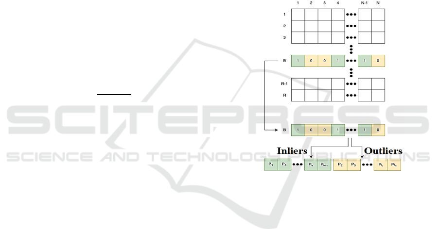
In the kernel of the voting, function both gather
and scatter operations are used. The gather operation
is used when reading the models, while the scatter
operation is used to check which points are inliers and
which are outliers for a certain model. For parallel
processing reasons, a binary matrix is used to flag the
points which are inliers with a flag of 1 and the
outliers have a flag of 0. Furthermore, an array is used
to count the number of inlier points of each model.
The binary matrix has R rows and N columns, where
R is the number of RANSAC models and N is the
number of 3D points. The flags in the binary matrix
are set based on the distance of the point to the plane
described by one of the models. If the distance is
smaller than a predefined threshold, the entry in the
matrix corresponding to that point is set to 1 and the
position of the model in the array corresponding to
the plane is incremented. The modification of the
flags in the binary matrix is done without any issues
due to the fact that an execution thread is responsible
for each cell of the matrix.
Figure 1: Depiction of the parallel point separation process.
However, for the incrementation of the counters
corresponding to each of the R models, race
conditions can appear because multiple threads will
aim to increment the counter of a model at the same
time. This issue is solved using atomic operations.
In the next step, the RANSAC model having the
maximum number of inliers is selected. Using the
selected model, the 3D points are stored in two arrays,
one for inliers and one for outliers, for easier
processing. The points are split into two arrays based
on the values from the binary matrix, from the row
corresponding to the best-selected model. The points
having a value of 0 will be introduced into the outlier
array and the ones that have a value of 1 will be
introduced into the inlier array. A counter is used for
each array to add sequentially the points into the
arrays, and the counters are incremented using atomic
addition operations since multiple threads may wish
to include the points at the same time. In Figure 1 an
intuitive depiction of the process described above is
VISAPP 2023 - 18th International Conference on Computer Vision Theory and Applications
782
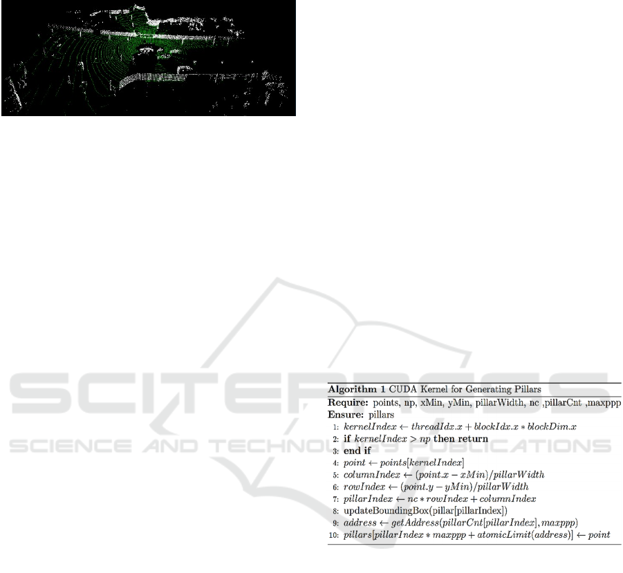
illustrated. The results of the described method can be
seen in Figure 2.
Figure 2: The results of the road segmentation with green
and the remaining object points with white.
3.2 Object Detection
For clustering 3D points, we are using an approach
that is based on the point cloud density and plays an
important role in identifying non-linear structures.
This approach is commonly known as a density-based
spatial clustering of applications with noise or
DBSCAN (Deng, 2020). The algorithm uses two
concepts called density of accessibility and density of
connectivity. A point P is said to be accessible by a
point Q if the distance from point P to point Q is
smaller than a predefined threshold. Furthermore, a
point P is said to be connected to a point Q if there
exists a point R between P and Q and the point R is
accessible from both P and Q. In DBSCAN two
parameters are required, a threshold distance which is
used for the two concepts of accessibility and
connectivity and a minimum number of points
required to create a cluster. The DBSCAN clustering
method can be parallelized because there are no race
conditions regarding the order in which we are
considering the points to be assigned to a cluster.
Furthermore, in our approach besides implementing a
parallel version of the DBSCAN algorithm, we are
also applying the approach on pillars.
The pillars are a type of voxel that have a height
equal to the scene height. The pillars have equal
dimensions and their width and length are equal to a
predefined size. The dimension of the pillars is
important since it can affect the performance and
precision of the object detection process.
In our approach, each point is assigned to a pillar
based on its x and y coordinates. The points are
analyzed in parallel and are assigned to the pillar to
which they belong. Because the pillars which are not
empty can have at times only a few points assigned
due to the point cloud sparsity in a certain region,
bounding boxes are used to obtain a more precise
representation of the objects than the pillar dimension
themselves. Bounding boxes of a pillar are of cuboid
shape containing all points from a pillar. The
bounding boxes of the pillars are formed as points are
assigned to certain pillars, and a bounding box is
created as soon as we assign the first point to the
pillar. Each time a point is added to the bounding box,
the box dimensions are updated if necessary.
Furthermore, if a pillar does not contain any point
does not have any bounding box associated. Each
pillar will belong to a single cluster and every point
from that pillar will belong to the cluster with which
the pillar is associated.
The first step in our clustering approach is to look
for a start pillar from which the generation of a cluster
can start. For a pillar to be valid and to be taken into
account, it has to have a minimum number of points
(the amount which is set in a configuration file before
running the program) and it has to not be previously
assigned to any other cluster. After selecting a start
pillar the neighboring pillars are analyzed in parallel
and are assigned to the current cluster if the pillar is
valid and accessible. The process ends when an
invalid pillar is found and the clustering does not
continue from that pillar. The algorithm mentioned
above increases the running time of the solution
compared to a standard approach applied only to
points. The pseudocode of the pillar generation kernel
is displayed below.
The meaning of the parameters is the following:
points represent the 3D points, np denotes the number
of points, xMin and yMin are the minimum
coordinates of the scene, pillarWidth is the width of a
pillar,
nc represents the total number of columns
from the pillar grid, pillarCnt represents the number
of points in each pillar. To each pillar, a maximum
number of points can be applied denoted in the
pseudocode by the variable
maxppp. The point that
is found at the position
kernelIndex is extracted
from the point list and the coordinates of the pillar to
which this point belongs is computed on the next two
lines. The pillar index is computed next, where
rowIndex and columnIndex are the rows and
column indices of the extracted point. In the next
instruction, the update of the cuboid bounding box is
realized using a scatter design pattern. Since there
Real-Time Obstacle Detection using a Pillar-based Representation and a Parallel Architecture on the GPU from LiDAR Measurements
783
exists a possibility that two points P
1
and P
2
want to
update the bounding box of a pillar at the same time,
which would lead to wrong cuboid dimensions, atomic
functions are used when updating the cuboid
coordinates thus avoiding erroneous bounding box
generation. Finally, the point is assigned to the pillar to
which it belongs. The list points from the pseudocode
contain all the obstacle points grouped based on the
pillar to which they belong. If the pillars would have
more points than the maximum space allocated, those
extra points would be ignored. For this reason, the
selection of
maxppp, must be done with caution. In
our implementation depending on the sensor used, we
identified two values for this constant.
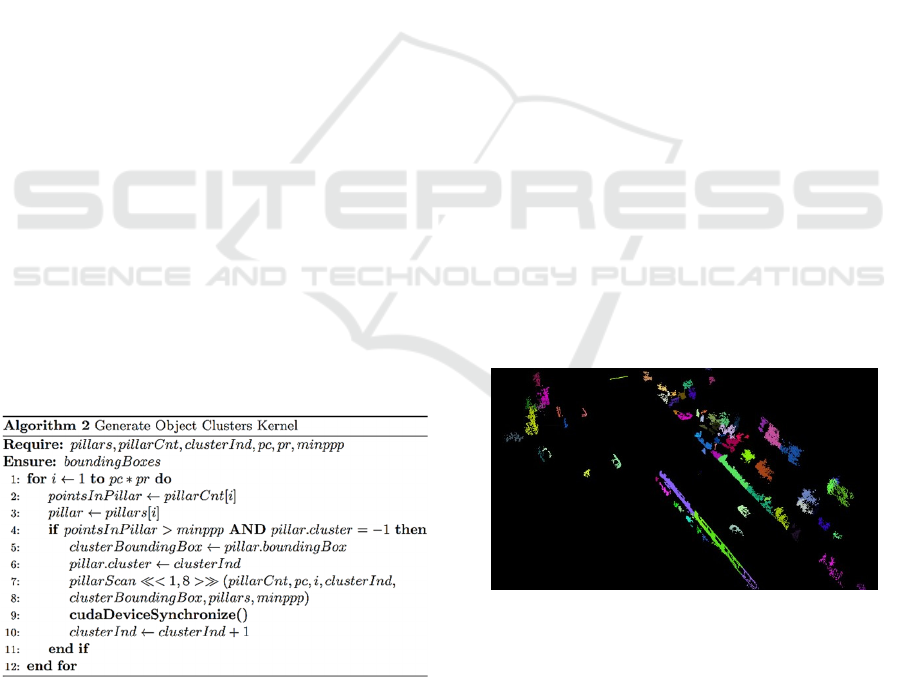
After generating the pillars, the kernel responsible
for the generation of object clusters is called. Initially,
the bounding box of a cluster is represented by the
bounding box of the pillar from which the box
generation process begins. When a new pillar is added
to the cluster the bounding box is updated if
necessary. The clustering algorithm in this kernel has
the following steps: first, a cluster ID is assigned to a
pillar, we perform a parallel bread first search starting
from the initial pillar, all the pillars assigned to a
cluster are marked as visited such that they are not
assigned to any other cluster, we repeat the three steps
mentioned before until there are no more valid pillars
to consider. In the parallel version of the algorithm,
the neighbors of an initial pillar are analyzed in
parallel to see if they are valid, and after the analysis,
step is finished the program is computed in parallel
from each of the identified valid neighbors. The
configuration for this kernel is 1 grid block and 1
thread because there is a need for only one such
kernel type. The pseudocode for this kernel is shown
in the code section below.
The parameters of this kernel have the following
meaning, pillars are the pillars generated by
Algorithm 1, pillarCnt represents the number of
points in each pillar, clusterInd are the cluster indices,
pc and pr are the maximum values for the pillar
column, and pillar row of the grid, minppp is a
constant that represents the minimum point per pilar.
The results are stored in the array called
boundingBoxes. In this kernel, we first iterate through
all the pillars from the grid and verify if there is a
sufficient number of points in that pillar by comparing
the number of points to a threshold. A pillar is marked
valid if it successfully passes this condition and has no
cluster assigned. A new object cluster is initialized with
the bounding box of the pillar from which the
clustering algorithm starts, and an object id is assigned
to the newly formed cluster. A dynamic kernel called
pillarScan is launched for forming the clusters. This
kernel is launched from within the generated object
clusters kernel using 1 grid block with 8 threads per
block. The 8 threads are launched because we wish to
analyze 8 neighbors of the current pillar from the
cluster. The neighboring clusters are checked if they
are valid, has no cluster assigned to it, and is within the
pillar grid bounds. If the analyzed pillar successfully
passes the conditions, the object bounding box is
updated and the object id is assigned to the analyzed
pillar. Furthermore, starting from that pillar a new
pillarScan kernel is launched with the same
configuration to recursively analyze the neighbors of
the pillar which was just analyzed. The updating of an
object cluster is similar to the update of the bounding
box of a pillar. Therefore, the same scatter pattern is
used and the race conditions which appear, are handled
similarly using atomic functions.
In Figure 3 the results of the object clustering can
be observed. The object clusters are illustrating a
different color for each object ID. The road surface
was removed from the images below in order to better
highlight the object clusters which were formed.
Figure 3: Object Clusters displayed with a different color.
3.3 Object Raffinement
Cluster and bounding box generation is followed by a
refinement step in which clusters that are close to
each other are merged into a single one. We analyze
each pair of bounding boxes by computing the
shortest distance between their corners. Two boxes
are merged if the shortest distance is less than a
VISAPP 2023 - 18th International Conference on Computer Vision Theory and Applications
784
predefined threshold, which in our case has the value
of 20 cm. After all pairs of bounding boxes are
compared and the bounding boxes which belong to
the same object are merged, the refinement process is
finished. Even though the refinement process could
be aided by other information from other modalities,
such as color or semantic information, in our work we
wanted to exploit the data from a single modality as
much as possible. The resulting bounding boxes will
be used in a late fusion framework.
4 EXPERIMENTAL RESULTS
The presented solution was implemented in C++
using the Point Cloud Library framework for
displaying the results and the CUDA framework for
writing the parallel code which ran on the GPU. The
program uses the CPU for sequential parts of the
program and the GPU for hardware acceleration and
parallelization. The solution was implemented on a
computer having an Intel Core i5-10300H processor
that has a frequency of 2.5 GHz and the GPU used is
NVIDIA GeForce GTX 1650. The solution was
tested on multiple other platforms in online and
offline scenarios, and the scenarios covered indoor
and outdoor situations.
We have measured the average running time of our
solution on the KITTI dataset and we have obtained an
average of 0.34 ms for the ground segmentation task
and 11.2 ms for the object clusterization task. It is
worth noting that multiple configuration parameters
were tested for the object detection part to identify
which offered the best running time and quality results.
Table I illustrates the running time of the solution
obtained using different variations of the configuration
parameters. The meaning of the symbols from Table 1
is the following: λ represents the maximum number of
points per pillar, β represents the minimum number of
points per pillar, ξ represents the value of the width and
length of a pillar and finally, µ represents the distance
threshold used for the RANSAC algorithm. The
running time for each configuration is also displayed in
Table 1.
Table 1: Different parameter configurations.
λ β ξ (m) µ Time(ms)
Se
t
1 350 15 0.4 0.2 9.5
Se
t
2 350 10 0.3 0.2 11.09
Se
t
3 350 5 0.2 0.2 11.2
For evaluating the quality of the proposed
clustering method, we use the KITTI data set and
evaluate it with respect to the intersection with the
cuboids provided by the benchmark. When using the
intersection metric an intersection threshold of 50%
is used to verify if an object has been correctly
detected. Even though the proposed solution is able
to successfully detect any object, the numerical
evaluation has been done only for the object class
having the label car. For the setups presented in Table
1, we have obtained the following quality results with
respect to the intersection metric: Set 1 – 70.45%, Set
2 – 75.13% and Set 3 – 88.33%.
We have also compared the proposed approach
with a clustering method based on k-d trees presented
by Sun Z et. al. using the same intersection metric and
the result obtained for the k-d tree clustering approach
show 71.3% accuracy on the KITTI dataset and a
running time of 10 FPS.
For evaluating the quality of the detected ground
plane, the files provided by Velas et. all. were used
which consist of 252 annotated scenes from the
KITTI tracking dataset. The metrics used were to
evaluate the quality of the ground detection were
accuracy, precision, recall and f1-score. The results
are shown in Table 2.
Table 2: Road detection results w. r. to different metrics.
Metric Experimental Result %
Accuracy 94.1
Precision 95.3
Recall 95.180
F1-Score 95.187
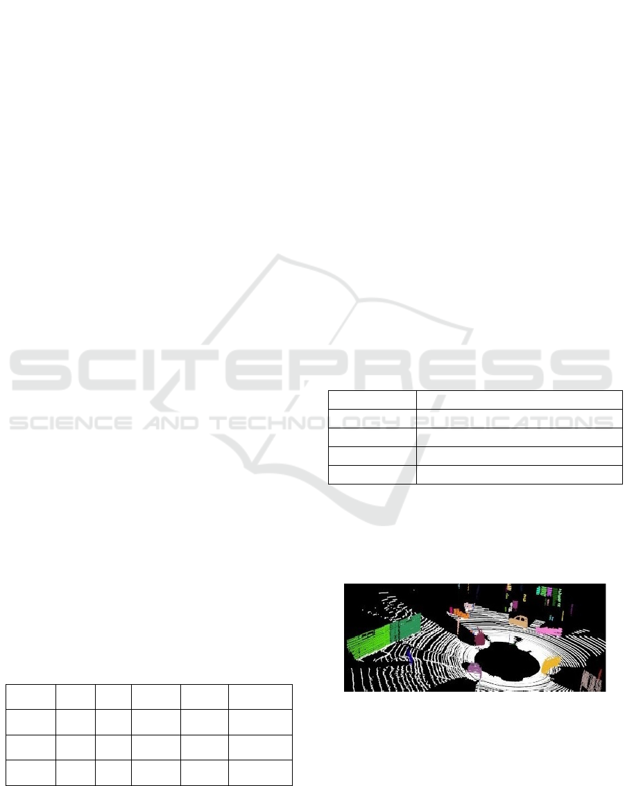
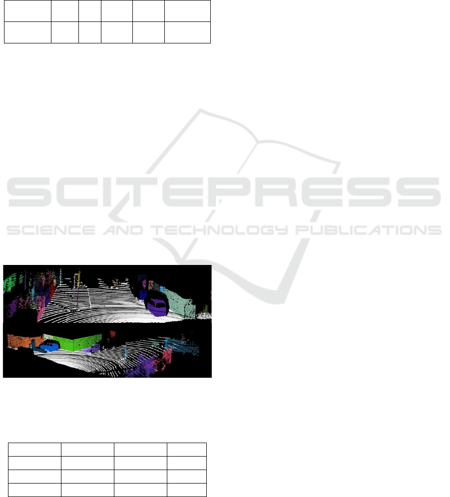
Some results obtained by applying the proposed
solution to different scenarios from the KITTI dataset
are presented in figures 4 and 5. For better
visualization, each cluster has been marked with a
different color and the road is shown with white.
Figure 4: Scene from an intersection where multiple objects
are present. The points belonging to an object have a
different color to better differentiate between objects.
The proposed solution was also tested in real time
scenario using a VLP 16 LiDAR. The only
modifications required for the application are the
Real-Time Obstacle Detection using a Pillar-based Representation and a Parallel Architecture on the GPU from LiDAR Measurements
785
values of the parameters from Table 1 and the
working interval of the application. The reason for
reducing the working interval for the application is
that the VLP 16 LiDAR has fewer points at larger
distances, than the LiDAR used in KITTI dataset. In
Table 4 the parameters used in the application with
VLP 16 LiDAR are illustrated. The meaning of the
parameters from Table 3 is the same as in Table 1.
Table 3: Parameters used with the VLP 16 LiDAR.
Parameter λ β ξ (m) µ Time(ms)
Value 350 1 0.4 0.16 3.5
The working intervals for the algorithm when
using the 16-layer LiDAR are X ∈[-20, 20], Y ∈
[50,50], Z ∈ [-2,2], the grid cell size is 16 cm x 16
cm. The number of RANSAC models is 200 for both
configurations.
The running time of the proposed
solution was also tested on different computer
configurations, including and embedded device.
Without loss in quality, the time results, in
milliseconds, of the evaluation on different devices
are illustrated in Table 4. For brevity, the platforms
on which the solution was tested were named A, B
and C. Platform A is the system on which the
application was developed which has the
configuration described at the beginning of this
section. Platform B has an Intel Core i7-11370H
processor having a 3.3 Ghz frequency and an Nvidia
GForce RTX 3070. Platform C is an Nvidia Jetson
TX2 development board
.
Figure 5: Different scenarios illustrating the results of the
proposed solution on real traffic scenes from the KITTI
dataset.
Table 4: Running time on different computing platforms.
A (ms) B (ms) C (ms)
Set 1 9.5 6.91 60.5
Set 2 11.09 7.6 66.2
Set 3 11.2 8.1 67
5 CONCLUSIONS
In this paper, we have presented a novel approach that
detects objects from 3D point clouds. The method has
been implemented in C++ and CUDA and has been
designed to run in real-time on the GPU. We first
presented the parallel architecture of the proposed
method contains four modules, each of them being
designed to run on the GPU: Pre-Processing, Ground
Surface Detection, Object Detection and Refinement.
The ground point segmentation approach was
necessary to separate the road points from the object
points. An elevation grid was used to perform
filtering of the points and a voting scheme using
multiple RANSAC models, that process data in
parallel, was developed to determine the road plane.
The points which did not belong to the road surface
were considered for the object detection part. An
original pillar-based representation was used for
clustering the 3D points into objects and the kernels
responsible for this task were described. The
proposed solution was evaluated using the KITTI
dataset and its running time was tested on multiple
computing platforms in indoor and outdoor scenarios.
ACKNOWLEDGMENTS
This work was supported by the Romanian Ministry
of Education and Research, through CNCS-
UEFISCDI, project number PN-III-P4-ID-PCE-
2020-1700, within PNCDI III.
REFERENCES
Muresan, M. P., Giosan, I., & Nedevschi, S. (2020).
Stabilization and validation of 3D object position using
multimodal sensor fusion and semantic segmentation.
Sensors, 20(4), 1110.
Lin, S. L., Li, X. Q., Wu, J. Y., & Lin, B. C. (2021,
November). Research on Overtaking Path Planning of
Autonomous Vehicles. In 2021 IEEE International
Future Energy Electronics Conference (IFEEC) (pp. 1-
4). IEEE.
Park, M. W., Lee, S. W., & Han, W. (2016, June).
Development of lateral control module for zone (u-turn)
maneuver of vehicle/driver cooperative autonomous
driving system. In 2016 IEEE Transportation
Electrification Conference and Expo, Asia-Pacific
(ITEC Asia-Pacific) (pp. 908-912). IEEE.
Capalnean, S., Oniga, F., & Danescu, R. (2019,
September). Obstacle Detection Using a Voxel Octree
Representation. In 2019 IEEE 15th International
VISAPP 2023 - 18th International Conference on Computer Vision Theory and Applications
786

Conference on Intelligent Computer Communication
and Processing (ICCP) (pp. 3-9). IEEE.
McCrae, S., & Zakhor, A. (2020, October). 3D object
detection for autonomous driving using temporal
LiDAR data. In 2020 IEEE International Conference on
Image Processing (ICIP) (pp. 2661-2665). IEEE.
Meyer, M., & Kuschk, G. (2019, October). Automotive
radar dataset for deep learning based 3d object
detection. In 2019 16th european radar conference
(EuRAD) (pp. 129-132). IEEE.
Wu, Z., Zhao, T., & Nguyen, C. (2020, November). 3D
reconstruction and object detection for HoloLens. In
2020 Digital Image Computing: Techniques and
Applications (DICTA) (pp. 1-2). IEEE.
Lei, J., Guo, T., Peng, B., & Yu, C. (2021, September).
Depth-Assisted Joint Detection Network For
Monocular 3d Object Detection. In 2021 IEEE
International Conference on Image Processing (ICIP)
(pp. 2204-2208). IEEE.
Muresan, M. P., Raul, M., Nedevschi, S., & Danescu, R.
(2021, October). Stereo and Mono Depth Estimation
Fusion for an Improved and Fault Tolerant 3D
Reconstruction. In 2021 IEEE 17th International
Conference on Intelligent Computer Communication
and Processing (ICCP) (pp. 233-240). IEEE.
Chen, X., Kundu, K., Zhu, Y., Ma, H., Fidler, S., &
Urtasun, R. (2017). 3d object proposals using stereo
imagery for accurate object class detection. IEEE
transactions on pattern analysis and machine
intelligence, 40(5), 1259-1272.
Navab, N., Unger, C. (2011). http://campar.in.tum.de/
twiki/pub/Chair/TeachingWs11Cv2/3D_CV2_WS_20
11_Stereo.pdf
Lang, A. H., Vora, S., Caesar, H., Zhou, L., Yang, J., &
Beijbom, O. (2019). Pointpillars: Fast encoders for
object detection from point clouds. In Proceedings of
the IEEE/CVF conference on computer vision and
pattern recognition (pp. 12697-12705).
Toker, O., & Alsweiss, S. (2020, March). mmWave radar
based approach for pedestrian identification in
autonomous vehicles. In 2020 SoutheastCon (pp. 1-2).
IEEE.
Chen, Q., Sun, L., Cheung, E., & Yuille, A. L. (2020).
Every view counts: Cross-view consistency in 3d object
detection with hybrid-cylindrical-spherical
voxelization. Advances in Neural Information
Processing Systems, 33, 21224-21235.
Shi, W., & Rajkumar, R. (2020). Point-gnn: Graph neural
network for 3d object detection in a point cloud. In
Proceedings of the IEEE/CVF conference on computer
vision and pattern recognition (pp. 1711-1719).
Yang, B., Luo, W., & Urtasun, R. (2018). Pixor: Real-time
3d object detection from point clouds. In Proceedings
of the IEEE conference on Computer Vision and
Pattern Recognition (pp. 7652-7660).
Chu, P., Cho, S., Sim, S., Kwak, K., & Cho, K. (2017). A
fast ground segmentation method for 3D point cloud.
Journal of information processing systems, 13(3), 491-
499.
Kraemer, S., Stiller, C., & Bouzouraa, M. E. (2018,
October). LiDAR-based object tracking and shape
estimation using polylines and free-space information.
In 2018 IEEE/RSJ International Conference on
Intelligent Robots and Systems (IROS) (pp. 4515-
4522). IEEE.
Oliveira, M., Santos, V., Sappa, A. D., & Dias, P. (2016).
Scene representations for autonomous driving: an
approach based on polygonal primitives. In Robot
2015: Second Iberian Robotics Conference (pp. 503-
515). Springer, Cham.
Oniga, F., & Nedevschi, S. (2009). Processing dense stereo
data using elevation maps: Road surface, traffic isle,
and obstacle detection. IEEE Transactions on Vehicular
Technology, 59(3), 1172-1182.
Muresan, M. P., Nedevschi, S., & Giosan, I. (2017,
September). Real-time object detection using a sparse
4-layer LIDAR. In 2017 13th IEEE International
Conference on Intelligent Computer Communication
and Processing (ICCP) (pp. 317-322). IEEE.
Zhou, Y., & Tuzel, O. (2018). Voxelnet: End-to-end
learning for point cloud based 3d object detection. In
Proceedings of the IEEE conference on computer vision
and pattern recognition (pp. 4490-4499).
Liu, W., Anguelov, D., Erhan, D., Szegedy, C., Reed, S.,
Fu, C. Y., & Berg, A. C. (2016, October). Ssd: Single
shot multibox detector. In European conference on
computer vision (pp. 21-37). Springer, Cham.
Chen, Y., Liu, S., Shen, X., & Jia, J. (2019). Fast point r-
cnn. In Proceedings of the IEEE/CVF international
conference on computer vision (pp. 9775-9784).
Yang, B., Liang, M., & Urtasun, R. (2018, October). Hdnet:
Exploiting hd maps for 3d object detection. In
Conference on Robot Learning (pp. 146-155). PMLR.
D. Deng, DBSCAN Clustering Algorithm Based on
Density, 2020 7th International Forum on Electrical
Engineering and Automation (IFEEA), 2020, pp. 949-
953
Velas, M.; Spanel, M.; Hradis, M.; Herout, A. CNN for
Very Fast Ground Segmentation in Velodyne LiDAR
Data. In Proceedings of the 2018 IEEE International
Conference on Autonomous Robot Systems and
Competitions (ICARSC), pp. 97–103.
Sun Z, Li Z, Liu Y (2020) An improved lidar data
segmentation algorithm based on euclidean clustering.
In: Proceedings of the 11th international conference on
modelling, identification and control, pp 1119–1130
Real-Time Obstacle Detection using a Pillar-based Representation and a Parallel Architecture on the GPU from LiDAR Measurements
787
