
Real-Time Volume Editing on Low-Power Virtual Reality Devices
Iordanis Evangelou
a
, Anastasios Gkaravelis
b
and Georgios Papaioannou
c
Department of Informatics, Athens University of Economics and Business, Athens, Greece
Keywords:
Virtual Reality, Ray Casting, Volume Graphics.
Abstract:
The advent of consumer-grade, low-power, untethered virtual reality devices has spurred the creation of numer-
ous applications, with important implications to training, socialisation, education and entertainment. However,
such devices are typically based on modified mobile architectures and processing units, offering limited capa-
bilities in terms of geometry and shading throughput, compared to their desktop counterparts. In this work we
provide insights on how to implement two combined and particularly challenging tasks on such a platform,
those of real-time volume editing and physically-based rendering. We implement and showcase our techniques
in the context of a virtual sculpting edutainment application, intended for mass deployment at a virtual reality
exhibition centre.
1 INTRODUCTION
Today, consumer virtual reality (VR) headsets offer
unprecedented image clarity and movement freedom.
Coupled with vision-assisted spatial tracking and nat-
ural, 6-DoF interaction, these untethered, standalone
VR systems provide an incredibly immersive VR ex-
perience in a multitude of applications, ranging from
VR games and social networking to training and sim-
ulation applications. Despite the fact that modern VR
headsets are more than capable to display 3D con-
tent at the very demanding frame rates and latency
required for comfortable immersive stereo, their low
power consumption and reduced weight constraints
limit the devices’ capabilities in terms of geome-
try and shading throughput, when compared to their
desktop counterparts. This means that high-fidelity
graphics pipelines that rely on ray tracing, or inten-
sive geometry processing methods cannot be imple-
mented efficiently in the underlying architectures and
limited hardware resources of typical untethered VR
systems. In most cases, applications are limited to
a few hundreds of textured and directly lit polygons
and even forgo dynamic lighting in many cases, to
keep rendering passes down to a minimum and pixel
shaders simple. Going beyond the typical rendering
tasks in such a setting, is quite challenging, not only
due to the hardware limitations of standalone VR sys-
tems, but also due to the necessary rigidity of typ-
a
https://orcid.org/0000-0003-4556-390X
b
https://orcid.org/0000-0002-9673-2462
c
https://orcid.org/0000-0003-4774-0746
ical game engines used for the application develop-
ment. In our case, we wanted to perform real-time
editing of solid geometry and the respective display
of the result using physically admissible shading. As
explained next, such an application requires an in-
tensive geometry processing stage and results in too
many primitives for a low-power rendering platform
to handle. This paper presents the methodological
approach used to perform real-time volumetric edit-
ing and display, combining techniques such as mul-
tiview voxelisation, image-domain ray marching and
stochastic visibility checks. The resulting application,
intended for mass deployment at a virtual reality ex-
hibition centre, was developed in Unity with custom
shaders and was able to run at 68 frames per second
on an Oculus Quest 2.
1.1 The Target Application
The goal was to implement an immersive application,
where a solid block of material could be carved and
shaped in a fully dynamic and therefore unpredictable
manner, to create a new form, like sculpting and clay
modelling in the physical world (Figure 1). The user
has access to a selection of electric rotary and impact
tools with various drill bits as well as a ”fill gun” that
deposits modelling paste on the sculpture for additive
editing and corrections. The tools can be exchanged
by picking them up from a workbench near the model
using one of the 6-DoF controllers. The removal or
deposition of material is performed by touching the
drill bit or nozzle of the virtual tool onto the surface of
110
Evangelou, I., Gkaravelis, A. and Papaioannou, G.
Real-Time Volume Editing on Low-Power Virtual Reality Devices.
DOI: 10.5220/0011779600003417
In Proceedings of the 18th International Joint Conference on Computer Vision, Imaging and Computer Graphics Theory and Applications (VISIGRAPP 2023) - Volume 1: GRAPP, pages
110-118
ISBN: 978-989-758-634-7; ISSN: 2184-4321
Copyright
c
2023 by SCITEPRESS – Science and Technology Publications, Lda. Under CC license (CC BY-NC-ND 4.0)
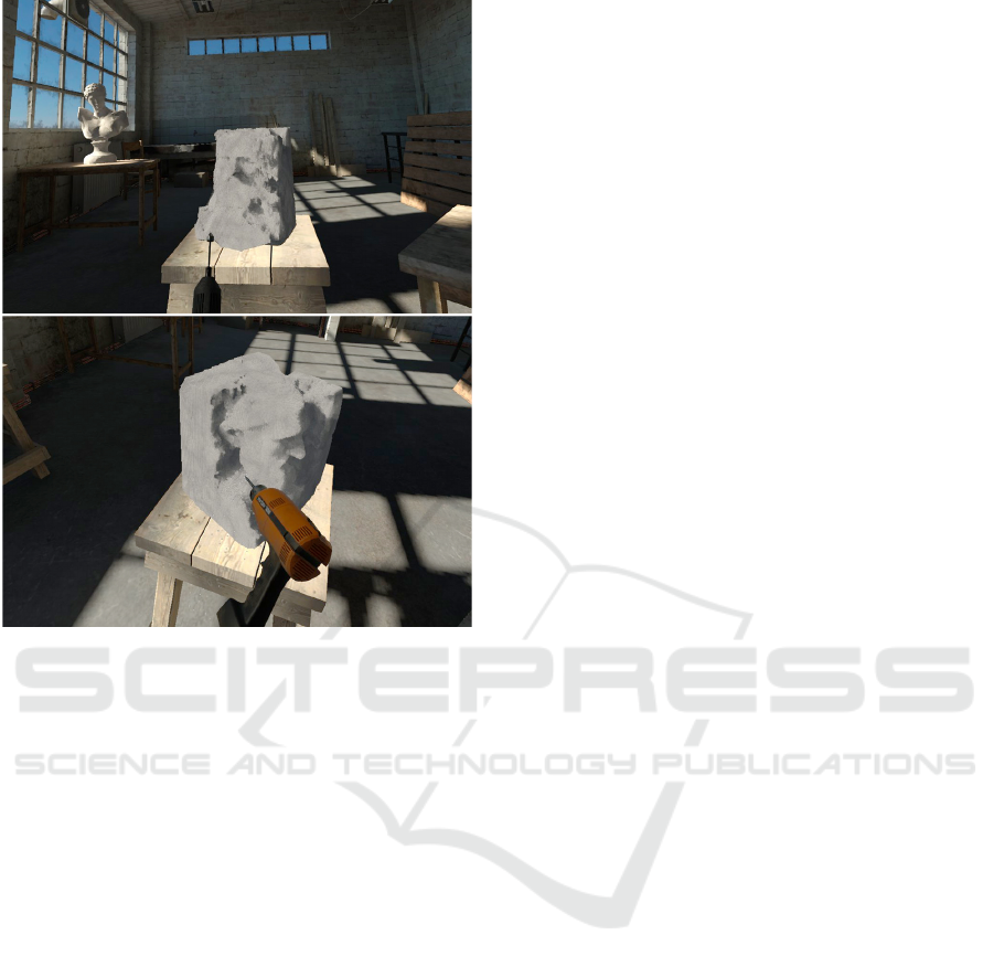
Figure 1: Screenshots from the virtual sculpting VR appli-
cation.
the sculpture (Figure 1 - bottom). The virtual sculpt-
ing application provides three sculpting modes: ex-
pert free-form modelling, constrained sculpting and
creative mode. In the first mode, the user starts with a
lump of rock, which must shape with the available
tools. The second mode is the constrained sculpt-
ing mode, which is intended for novice users and en-
forces an indestructible solid boundary. In essence,
the user ”reveals” a predefined figure by chipping
away material with the given tools. The third mode
is the creative mode, where the process starts from
an already sculpted shape, which the user can mod-
ify freely to personalise or transform it into some-
thing entirely different. After a predetermined time,
the user is signalled to stop editing and the resulting
model is exported as a watertight polygonal model for
3D printing in STL format. The user is given a unique
mnemonic visual identifier (badge) after the comple-
tion of the VR sculpting session that can be used for
requesting the model to be send via email or ordering
the 3D printout of the model at a dedicated booth. The
VR application packs and uploads the STL model on
a dedicated server for this task. Apart from the typi-
cal technical requirements for high and stable framer-
ate and responsiveness valid for all VR applications,
the particular edutainment installation had to be able
to run on standalone VR headsets for the following
reasons. First, the application should be deployed in
multiple devices simultaneously in a large space, in
order to accommodate multiple visitors. Second the
deployment should be cable-free for the safety of the
visitors and the easy access of the exhibition person-
nel to assist the users. Finally, device redundancy,
maintenance, replacement and sanitisation introduce
logistic constraints on the size, weight and compact-
ness of the chosen solution.
1.2 Technical Challenges
The implementation of the volume editing and render-
ing for the standalone VR system is especially chal-
lenging and required an innovative approach to vol-
ume editing and display, as explained in the follow-
ing sections. Solid modelling at such a fine-grained
and unstructured manner can only be performed on
volumetric representations, either single-level or hi-
erarchical. To provide ground for enough detail on
the sculpted figures, but also reduce discretisation ar-
tifacts during rendering at a typical working distance,
a volume representation of no less than 128
3
voxels
must be used. At each frame, collision of the tool’s
active surface with the volume elements must be de-
tected to both allow and block the tool from pene-
trating the boundary surface of the edited volume and
mark the affected elements for modification. To al-
low inter-operation with the collision and event sys-
tem of the game engine, this task must be performed
on the CPU and take as little time as possible. Note
that in the particular volume editing application, an
additional geometry processing task must take place:
that of volume island elimination. As the user pro-
gressively removes material from the solid model, at
some point bits may end up levitating in the air, un-
supported and disconnected from the main body of
the model. These regions must be identified and their
elements removed. This step can be performed by a
graph-processing algorithm, which however is quite
expensive, especially at the required volume resolu-
tion. After all necessary changes are made to the volu-
metric representation, the modified boundary surface
of the model must be rendered. Typically this entails
one of two approaches: either conversion to triangu-
lar mesh and rasterisation using the pipeline provided
by the game engine, or direct volume visualisation
using ray marching. The first means that the vol-
ume must be triangulated, either globally or locally
at the region of change, using a variant of the march-
ing cubes algorithm (Lorensen and Cline, 1987). Al-
though local updates are efficient, updating vertex and
element buffers of variable length is not. Further-
Real-Time Volume Editing on Low-Power Virtual Reality Devices
111

more, the total number of triangles resulting from the
volumetric model can be several hundred thousands,
which renders this option inapplicable to untethered
VR. Triangulation becomes even more problematic,
since the triangulated meshes must be smoothed and
vertex normals estimated in the updated regions and
their boundaries. On the other hand, direct volume
rendering using ray marching can be performed in a
more controllable manner, with the option to trade
visual fidelity for speed in order to maintain the de-
sired frame rate. However, it implies two things:
first, the rendering pipeline of the game engine must
be circumvented for the particular game object and
second, the volume representation must be resident
on GPU memory and constantly updated. The latter
proved to be an especially heavy task in Unity, which
does not provide access to texture subloading func-
tionality. The custom rendering for the sculpted vol-
ume translates to implementing all shading with cus-
tom shaders. Furthermore, since the game engine is
agnostic to the volumetric representation, interaction
with light sources, including shadows, cannot use the
rendering passes of the former. A positive side-effect
of this is that custom lighting allows us to model more
realistic light-volume interaction, more suitable for
the often translucent materials used.
2 RELATED WORK
We present here a brief overview of prior art relevant
to the tasks at hand in our application, i.e. geometry
representation for dynamic updates and visualisation
approaches for such data. We deem a review of the
general volume editing and related VR applications
out of the scope of our discussion, since we focus on
the specific case of untethered VR, where prior art is
scarce.
Volumetric Representations. Since direct editing of
geometric meshes with arbitrary operations can lead
to heavy re-tesselation and topology changes, a tri-
angulated mesh representation is typically avoided in
digital sculpting applications. Even more so in our
case, where the computing resources of an untethered
VR system are limited. On the other hand, volumetric
representations offer a generic and fast approach to
represent arbitrary shapes, at a user-controlled preci-
sion. Volumetric data, expressing the presence of the
geometric shape at a given spatial partition, can eas-
ily be accomplished using a uniform grid representa-
tion (Lagae and Dutr
´
e, 2008), which is an inexpensive
choice in terms of construction and update, but can
become prohibitively expensive on storage require-
ments. Alternatively, resorting to image-based regular
grids (Vardis et al., 2016; Karabassi et al., 1999) can
be lighter to maintain and equally fast to update on ev-
ery consecutive frame. Complexity of spatial queries
is constant on both of these structures but can induce
divergence if variable size lists of primitives are main-
tained for each voxel (for analytic computations), in-
stead of being treated as discretised boolean volume
presence (occupancy) indicators. To represent and
process larger and more detailed geometric shapes,
uniform grids can be hierarchically built. Hierarchi-
cal approaches include the popular Sparse voxel oc-
tree (Laine and Karras, 2010) and hierarchical irreg-
ular grids (P
´
erard-Gayot et al., 2017), but such meth-
ods are inapplicable to our case, since we not only
need per-frame updates of the data structure, but there
is also limited amount of memory bandwidth for data
representation.
Volume - Ray Intersection Queries. Depending
on the voxel grid representation, ray traversal or
marching within a volume towards a potential hit cell
can be achieved either analytically (Amanatides and
Woo, 1987), exhaustively evaluating all possible ray
- cell hits along the footprint of a ray or, approxi-
mately using a digital differential analyzer (DDA) al-
gorithm (McGuire and Mara, 2014). Both approaches
can be adapted either for image-domain or world-
space ray traversal and also account for hierarchi-
cal representations, as in the Quadtree Displacement
Mapping image-space ray traversal (Drobot, 2010).
In our work, to minimise thread divergence within
fragment invocation, we employ a variant of the
DDA algorithm with a constant number of samples,
since the resolution of the volume is fixed, hence the
worst case traversal length. Signed distance fields
(SDFs) (Bloomenthal and Wyvill, 1997) is another
popular approach to quickly traverse empty space in
ray marching and represent level sets of complex pro-
cedural shapes. A distance field is a spatial func-
tion that reports the minimum distance of a given
point from the level set. The SDF replaces the abso-
lute distance with a signed one, indicating the sided-
ness. This information can be used for safely skipping
empty space while traversing a volume, whose occu-
pancy boundary can be considered a discretised level
set isosurface. It can also be used to iteratively com-
pute intersections with the isosurface. We do not gen-
erate a full distance field for our model, which would
be required for empty space skipping, since the vol-
ume is constantly updated and SDF computation is
rather expensive. However, we exploit a generic algo-
rithm to identify the closest intersection point on the
SDF, the sphere tracing (Hart, 1995), to better approx-
imate a smooth shading point and normal from a ray
marching hit point (see Section 4.2).
GRAPP 2023 - 18th International Conference on Computer Graphics Theory and Applications
112
Min/max range buers
Quick marching step:
single buer pair checks
Nested, full marching step:
check all buer pairs
z
min
buer
z
min
buer
x
min
buer
x
min
buer
x
max
buer
x
max
buer
z
max
buer
z
max
buer
Image-based volume
representation
Image-space ray marching
Drill bit
eective
sphere
Range buer
volumetric editing
Figure 2: Image-based volume representation, editing and rendering via image-domain ray marching.
3 VOLUME EDITING
The application provides a range of tools to the user in
order to perform two main tasks: a) carve and remove
material from the sculpted mass and b) deposit new
material over the edited geometry, to enable correc-
tions in a plausible manner. Volumetric editing occurs
at each application update iteration and at each update
cycle, the selected tool interacts with the shell of the
volumetric representation up to a small depth, using
either a spherical or rectangular cutter/filler. These
primitives are fast to analytically intersect with the
volumetric cells, but other shapes can also be inte-
grated, if required.
3.1 Collision Detection
Collision detection with the elements of the discre-
tised volume of fixed resolution can be done in lin-
ear time with respect to the intersected volume mass.
To allow for the detection of arbitrary overlaps be-
tween the sculpted volume and the tool tip primitive,
the cutter/filler primitive is transformed to the sculp-
ture’s local reference frame. The bounding volume
of the transformed primitive is computed and dis-
cretized at the granularity of the sculpted volume, and
each voxel of the transformed primitive bounding vol-
ume is checked for collision with the sculpted volume
voxel state. We perform this linear pass over the vol-
ume samples on the CPU, since multiple updates must
take place and feedback to the game logic has to be
provided, before updating the GPU-side representa-
tion, such as tool transformation freeze for penetra-
tion avoidance and controller force feedback.
3.2 Volume Representation
The representation of the solid’s volume requires its
content to be resident and updated in both the host
and the device side to properly visualise it. There-
fore, data transactions on every frame for a fixed bi-
nary grid (e.g. 128
3
in our case) can cause redundant,
heavy updates and data transfer operations, since the
user is only interacting with a small volume parti-
tion near the sculpt surface. Inspired from the depth-
buffer-based voxelisation technique by (Karabassi
et al., 1999), to overcome this issue, instead of using
a voxel array for the volumetric data representation,
we model the binary grid using 3 two-dimensional
arrays. The cells of these arrays store the minimum
and maximum ranges of the occupied field along each
dimension (see Figure 2 - left). The editing opera-
tions are then transformed from flipping the state of
each binary voxel to, shrinking or widening the stored
ranges accordingly (see Figure 2 - middle). This re-
duces update operation complexity and the memory
requirements from cubic to quadratic with respect to
the grid resolution. Implementation-wise, the range
maps are compacted in a single texture array, with
one layer for each major axis. Min/max ranges are
stored normalised with single-byte precision as a two-
channel texture, as all intersection computations are
performed in the local reference frame of a unit cube,
representing the effective working volume. Using a
single texture for both min/max values facilitates co-
herent texture access and checking of a ray marching
step with a single texture fetch (see Section 4.1). The
only drawback of this image-based volumetric repre-
sentation is that it cannot model every possible shape
as it cannot represent internal cavities or empty space
Real-Time Volume Editing on Low-Power Virtual Reality Devices
113

Expert (free-form) mode
Novice (constrained) mode
Shape modication mode
Figure 3: The three editing modes.
in general that is not visible to at least one axial pro-
jection. Due to the nature of the task at hand though,
this is not an issue in our application, since all opera-
tions occur on the outer shell of the sculpted volume,
which is always visible in the range maps.
3.3 Volume Initialisation
The application operates in three different modes: a)
free-form sculpting, starting from a roughly cut lump
of material, b) constrained sculpting, initialised as in
the first case and c) surface modification, where the
user processes an already formed shape. These modes
are presented to the user in an introductory screen, as
shown in Figure 3. Depending on the mode, the vol-
ume is initialised by extracting the 3 axial range map
pairs using an approach similar to the depth buffer
projection of (Karabassi et al., 1999). For modes (a)
and (b), a pre-modelled lump of stone is sampled and
used as the starting shape, whereas for mode (c), an
easy to modify figure is used. We deliberately chose a
nondescript toy model for this operation, since we did
not want the user to operate on and thus probably de-
face a well-known historical figure. Range maps are
computed by a conservative software triangle voxeli-
sation on the CPU, i.e. switching on all voxels inter-
sected by the triangles, followed by voxel projection
on the range maps. This is available as a Unity pre-
processing plugin from within the editor. The initial
range maps need not be recomputed every time the
application is initialised, so they are saved as assets
and packaged along with the rest of the content.
3.4 Disconnected Part Elimination
As mentioned in Section 1.2, the application must be
able to recognise at run time parts that are discon-
nected from the main body and are not supported from
the ground and remove them. To handle this, we em-
ploy a flood fill algorithm, starting from the ground
voxels and traversing the grid upwards. First, we
transform the range maps into a binary voxel grid and
then traverse the volume. Voxels that were not visited
during this process should be removed, by trivially
updating the range values at the corresponding range
maps. We update the contents of the original range
maps by traversing the valid intervals of each coor-
dinate and setting the new ranges based on the mini-
mum and maximum voxel coordinates marked as vis-
ited. We employ two additional modifications on this
step to maintain interactive frame rates at run time.
First, we assume that valid voxels appear only around
the 6-neighbourhood of the pivot voxel (axis-aligned
neighbours), instead of visiting all 26 adjacent vox-
els. This is a natural simplification in our case, since
exclusively diagonal connections would imply an un-
stable structure anyway. Second, we amortise the ex-
ecution of this operation over multiple frames by ex-
ploiting the coroutine programming pattern. This is
achieved through splitting the flood fill loop and dis-
tributing the task over multiple consecutive frames
until the sculpting volume has been completely pro-
cessed. We have experimentally set the coroutine
to yield at 100K flood fill iterations, that results in
a good balance between smooth runtime experience
and prompt removal of excess material.
3.5 Constrained Sculpting
In the constrained sculpting mode, which is intended
for novice users and children, a target shape is hidden
within the initial lump of material. The user grad-
ually removes material to reveal the intended form
within. To implement such a function, certain vox-
els should be specially marked as irremovable, so that
any editing operation refrains from altering their state
(see Figure 4). In our image-based volume represen-
tation, this simply translates to using an additional set
of range maps, which comprise the masked volume
and are checked prior to modifying the intervals in the
primary range maps for a particular voxel projection.
The masking mechanism was straightforward to inte-
grate within the volume editing step at an insignificant
processing cost.
GRAPP 2023 - 18th International Conference on Computer Graphics Theory and Applications
114

z
min
buerx
min
buer x
max
buer z
max
buer
Editable volume Irremovable
volume
Masked volume/range
Figure 4: Volumetric masking for constrained sculpting.
Additional range maps signify the axial ranges, where vox-
els cannot be modified.
3.6 Geometry Export
The volume editing in our application case results in
a tangible output. Although we have no noteworthy
contribution to this stage, we present it here for com-
pleteness. When the editing session is concluded, the
image-based volumetric information is converted to a
mesh via an implementation of the Marching Cubes
method (Lorensen and Cline, 1987). The resulting
mesh is further smoothed out by applying two iter-
ations of a Laplacian smoothing kernel of one-voxel
radius at the neighbourhood of each vertex (Sorkine,
2005), and uploaded to a remote server in STL for-
mat for offline 3D printing. The particular filter size
removes discretisation artifacts but retains geometric
feature details.
4 VOLUME RENDERING
During rendering, the sculpted object is rasterised us-
ing the standard primitive shape of a unit cube, trans-
formed to take up the intended size and final position-
ing in space. However, we replace the standard game
engine’s forward pass fragment shader with a custom
one to perform all ray marching and lighting compu-
tations.
4.1 Ray Marching
As is typical in all modern rasterisation-based ray
marching applications, starting from the interpolated
object-space position of the (unit) cube at any given
fragment in the fragment shader, we form a ray
traversing the volume of the bounding cube inwards.
However, in our case, ray traversal occurs in the im-
age domain of the range maps, in a similar manner to
screen-space ray tracing (McGuire and Mara, 2014).
Normally, to evaluate each ray marching step, the oc-
cupancy (or density) of the voxel corresponding to
the ray sample would be checked and the ray traver-
sal terminated at a point between the occluded and
unoccluded step. In our case, for each ray step this
check would normally pertain to three texture fetches
and a range check with the min/max values stored
in the corresponding buffer cells on each major axis
projection. However, we take advantage of the ax-
ial separation of the projected geometry to efficiently
and conservatively traverse empty space with a single
fetch at each ray step. Instead of continually check-
ing all three range buffer pairs, we only perform the
ray traversal on the range map corresponding to the
axis most parallel to the user’s view direction (quick
marching step in Figure 2 - right). If a ray hit is de-
tected, only then we proceed to a second, nested ray
marching loop that checks the remaining two axial
range map pairs for intersection (full marching step
in Figure 2 - right). Practically, this means that the
inner ray marching loop will run for a very few ray
steps, which correspond to either the single final hit
(a hit must be confirmed by all axial range maps) or
partially occluded positions in at least one range map.
The ray marching terminates either when the ray sam-
ple is enclosed by all three range queries or when the
ray exits the unit cube, in which case the fragment
is discarded. In terms of fragment shader implemen-
tation, since conservative traversal in the current VR
hardware can induce unnecessary divergence due to
the dimension size, we opt for a fixed number of reg-
ular steps (128 in our case). The two-step ray traver-
sal strategy described above omits redundant memory
accesses and improves memory access coherence.
4.2 Surface Normals Estimation
The solid volume should be presented to the user as a
smooth surface, agnostic to the underline representa-
tion. Using a simple localised estimator for the nor-
mal vector at the ray intersection point (e.g. assuming
cubical voxels) would invariably result in an unnatu-
ral, blocky appearance and the resulting image would
be plagued by screen-space aliasing similar to the ef-
fect of texture minification. We attempt to address
both issues by introducing a low-overhead approxi-
mation of the local surface around the voxel hit point.
Specifically, we extract the occupied voxels in the 6-
neighbourhood around the hit point for which we as-
Real-Time Volume Editing on Low-Power Virtual Reality Devices
115
sume that they are represented by a blob implicit sur-
face of radius equal to half the voxel size. Then we
trace a ray offseted by half the voxel size backwards
along the original ray direction, and report the closest
hit x
shading
on the signed distance field (SDF) com-
posed by the smooth union of these voxels. Evalu-
ating the normal vector at that location typically re-
quires the computation of the SDF value on the lo-
cal neighbourhood. Since this operation can be costly
on the current hardware, we replace it with the lin-
ear combination of the direction vectors from each
occupied voxel v
i
in the 6-neighbourhood towards the
evaluated intersection point x
shading
, weighted by their
inverse square distance (Shepard, 1968):
n = normalize
6
∑
i=1
δ
i
x
shading
− v
i
||x
shading
− v
i
||
2
!
(1)
where δ
i
is an indicator function with value 1 if the
voxel i is occupied and 0, otherwise.
4.3 Shadows and Surface Shading
With the ray intersection point and the normal esti-
mated, the surface shading can take place. To neu-
tralise the look of the sculpted surface, we assume
a Lambertian material with a procedural marble tex-
ture using Perlin noise (Perlin, 1985) precomputed
and stored in a 3D texture buffer. Due to the con-
stantly updated geometry of the sculpted volume and
the changing orientation of the subject (the sculpture
can be rotated on the stool for easier access), direct
illumination and visibility must be evaluated in real
time, per fragment. However, since we completely
dispense with the regular forward shading computa-
tions due to ray marching, we cannot rely directly on
any part of the game engine’s computed values, such
as the shadow map(s). Therefore, for the computation
of light source visibility for the direct lighting, we per-
form a hybrid visibility computation. First, for each
shaded point, we do an extra ray marching iteration,
albeit with a small number of steps (10 in our case)
towards the directional light of the scene. The ray
marching terminates at the surface of the bounding
cube. There, the shadow map is invoked to determine
the visibility for the rest of the interval between the
bounding box surface and the emitter. To account for
the translucent appearance of typical sculpting mate-
rials, we modify the visibility estimation in two ways.
First, instead of terminating the shadow rays early, we
allow the visibility term to be a continuous parame-
ter, corresponding to a piece-wise constant absorption
of the traversed material. We initialise visibility with
a maximum value of 1 and dampen it by a constant
factor (0.7 in our case) for each occupied sample en-
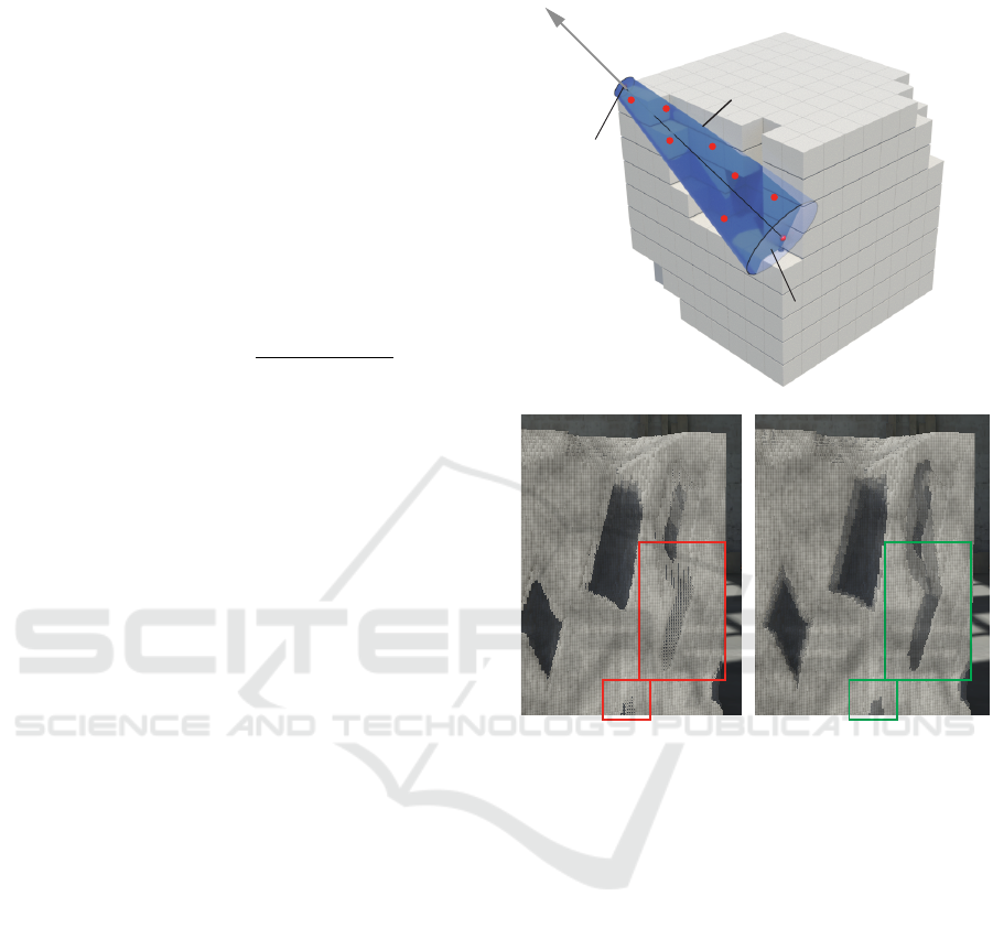
Shadow cone
Shaded voxel hit
Ray marching
end point
Stochastic visibility
Shadow map
look up
Figure 5: Visibility determination for volumetric shadows.
Top: ray marching sample dispersion and visibility voting
to account for subsurface scattering. Bottom: The effect
of cone sample dispersion on shadow artifacts at oblique
angles. Highlighted areas show aliasing artifacts (bottom-
left) and how they are remedied (bottom-right).
countered during the ray marching loop. This is simi-
lar to modelling an exponential decay of the visibility
factor according to the portion of the volume block-
ing the queried surface from the light source. Sec-
ond, we offset the ray samples away from the ray line
within a tapered cone whose apex corresponds to the
farthest ray box intersection (see Figure 5 - top). This
effectively introduces some shadow softening imitat-
ing subtle subsurface scattering for voxels near the
surface, while leaving voxels in deep recesses unaf-
fected. It also helps suppress artifacts of the visibility
transitions at the discretised geometry at very oblique
lighting angles. The effect is demonstrated in Fig-
ure 5 - bottom. The two cone radii correspond to 2×
and 0.25× the voxel side for the shaded point and
the ray segment terminus, respectively. Finally, the
indirect illumination component is approximately re-
GRAPP 2023 - 18th International Conference on Computer Graphics Theory and Applications
116
constructed from the spherical harmonics interpolated
from the static light probe group baked for the envi-
ronment, as provided by the Unity API.
5 RESULTS
We evaluate the performance of our method on an
Oculus Quest 2 VR headset. The application was
developed with Unity 2021.2.8 using the Oculus In-
tegration SDK 37.0. All performance measurement
were captured using the Oculus Developer Hub com-
panion software. We ran tests of our system on two
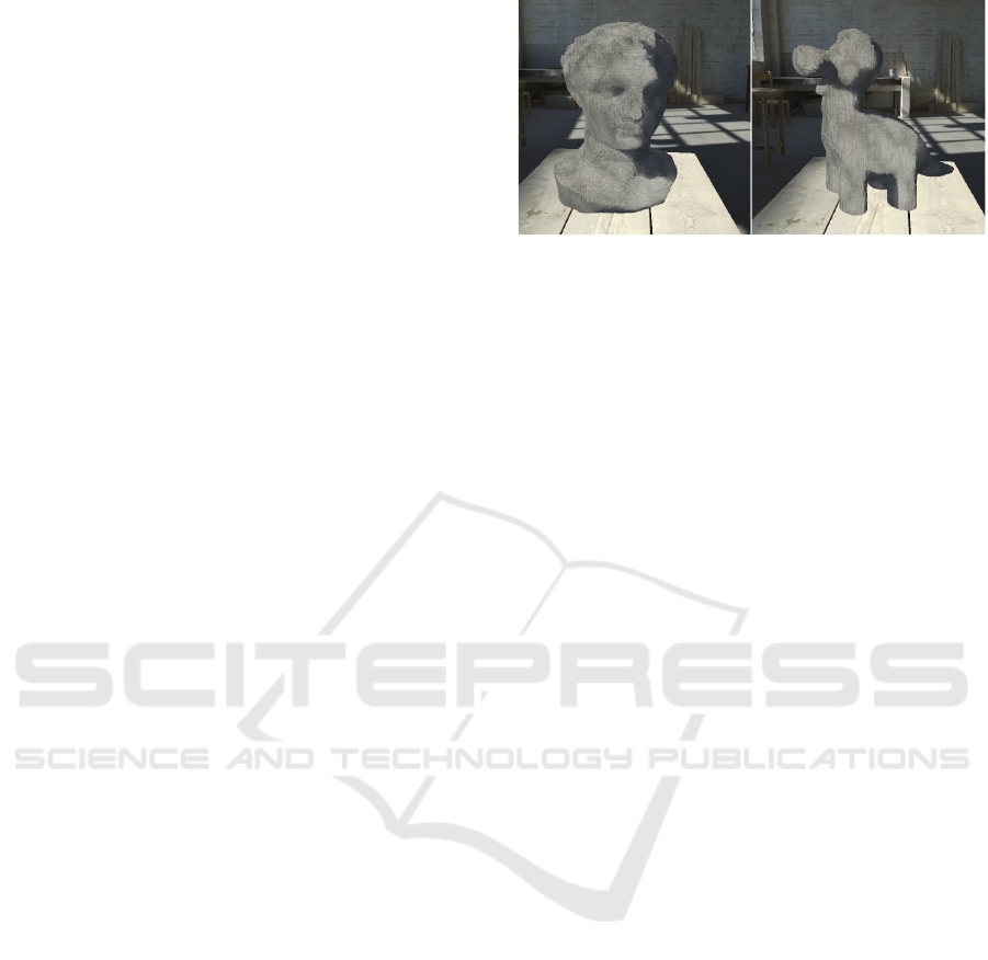
precomputed volumes (see Figure 6) to stress the
shader invocations workloads and avoid trivial frag-
ment evaluations as in the case of the initial, bound-
covering sculpting volume (see Section 3.3). Since
the VR headset is configured to operate at a consis-
tent framerate of 13.8ms per frame (72 frames per sec-
ond), we report the evaluation metrics of our method
relative to this target and averaged over different ori-
entations of the models.
Relative Rendering Step Impact. For the volume
rendering (Section 4), both examples operate on aver-
age at a 93.5% of the optimal performance, running
at 14.7ms per frame (68 fps), which is an acceptable
level for a smooth experience. Omitting the SDF eval-
uation as described in Section 4.2 and directly pro-
cessing the local shading with the intersection normal
found from the closest voxel hit, the performance is
sustained at the maximum level, with negligible im-
pact. We also confirmed that by retaining the ray
marching mechanism and SDF evaluation but, com-
pletely omitting the local shading (Section 4.3), still
maintains the maximum level of performance.
Ray Marching Performance. For the same exper-
imental setup, we compared the performance of ray
marching with the deferred full comparison of ray
samples described in Section 4 with that of a full ray
marching loop, without the differed evaluation of co-
ordinates. In the second case, we have registered a
performance degradation of up to 17% (60 fps). As a
final experiment, we also attempted to double the grid
resolution (see Section 4), to improve the granularity
and visual quality of the volume surface. The image-
based volume representation, due to the quadratic de-
pendence on volume resolution, instead of cubic for
spatial grids, does not render the increase prohibitive.
The performance hit is however noticeable, being on
average 31% (50 fps) for both example volumes. As
a result, for the currently presented method and hard-
ware specification, this resolution is marginally at-
tainable, but not recommended in terms of user ex-
perience and comfort.
Figure 6: Two precombuted volume exemplars rendered
with our proposed method, which were used for perfor-
mance evaluation and fine-tuning.
Temporal Amortisation of Material Removal.
Lastly, in Section 3.4, we proposed the use of
coroutine-based execution for amortising the compu-
tational cost of removing volumetric parts that are
disconnected from the main sculpt body. As it is
a computationally heavy method, naively executing
this step on every frame, results in a reduction of the
overall performance on the application’s main experi-
ence to 76ms per frame (13 fps) on average for both
models, which is prohibitive. Due to the high cost,
performing the full volume cleanup at once, but at a
slower rate, is also problematic, since it results in dis-
turbing framerate stuttering.
6 CONCLUSION
In this work, we proposed the mechanics to allow vol-
ume editing and rendering, two very demanding and
intertwined tasks to run in real-time on untethered VR
hardware. We described the necessary modifications,
based on a careful selection and adaptation of estab-
lished computer graphics methods and ideas and eval-
uated them in the context of a fully-functional and
mass-deployed virtual sculpting application. The pre-
sented methodology is suitable for volume editing ap-
plications similar to ours (e.g. 3D modelling). How-
ever, the generalised application of the image-based
volume representation to volumes of arbitrary com-
plexity, and especially when these should include in-
ternal cavities or very occluded parts, is challenging
and requires a multi-layer approach to handle cor-
rectly (Vasilakis et al., 2020). Finally, an interesting
approach, which requires further research and experi-
mentation, would be to completely replace the under-
lying data structure with a truncated Signed Distance
Field evaluator and respective data structure, in the
spirit of VDB (Museth, 2013), along with the appro-
priate operators for editing the volume. This could
greatly enhance the visual quality, minimise alias-
ing problems introduced by the discretization of the
Real-Time Volume Editing on Low-Power Virtual Reality Devices
117

edited volume and potentially allow for arbitrary sur-
face interactions. However, such an approach would
require careful optimisation, in order to strike a bal-
ance between image quality and acceptable perfor-
mance for an untethered VR device.
ACKNOWLEDGEMENTS
This work was funded by the Foundation of the
Hellenic World, Greece. Many thanks to Dimitrios
Christopoulos, for his constructive comments and
thorough application testing.
REFERENCES
Amanatides, J. and Woo, A. (1987). A fast voxel traversal
algorithm for ray tracing. Proceedings of EuroGraph-
ics, 87.
Bloomenthal, J. and Wyvill, B. (1997). Introduction to Im-
plicit Surfaces. Morgan Kaufmann Publishers Inc.,
San Francisco, CA, USA.
Drobot, M. (2010). Quadtree displacement mapping with
height blending. In Engel, W., editor, GPU Pro - Ad-
vanced Rendering Techniques, pages 117–138. A K
Peters / Taylor & Francis.
Hart, J. (1995). Sphere tracing: A geometric method for the
antialiased ray tracing of implicit surfaces. The Visual
Computer, 12.
Karabassi, E.-A., Papaioannou, G., and Theoharis, T.
(1999). A fast depth-buffer-based voxelization algo-
rithm. Journal of Graphics Tools, 4(4):5–10.
Lagae, A. and Dutr
´
e, P. (2008). Compact, fast and robust
grids for ray tracing. In ACM SIGGRAPH 2008 Talks,
SIGGRAPH ’08, New York, NY, USA. Association
for Computing Machinery.
Laine, S. and Karras, T. (2010). Efficient sparse voxel oc-
trees. In Proceedings of the 2010 ACM SIGGRAPH
Symposium on Interactive 3D Graphics and Games,
I3D ’10, page 55–63, New York, NY, USA. Associa-
tion for Computing Machinery.
Lorensen, W. E. and Cline, H. E. (1987). Marching cubes:
A high resolution 3d surface construction algorithm.
In Proceedings of the 14th Annual Conference on
Computer Graphics and Interactive Techniques, SIG-
GRAPH ’87, page 163–169, New York, NY, USA. As-
sociation for Computing Machinery.
McGuire, M. and Mara, M. (2014). Efficient GPU screen-
space ray tracing. Journal of Computer Graphics
Techniques (JCGT), 3(4):73–85.
Museth, K. (2013). Vdb: High-resolution sparse volumes
with dynamic topology. ACM Trans. Graph., 32(3).
Perlin, K. (1985). An image synthesizer. SIGGRAPH Com-
put. Graph., 19(3):287–296.
P
´
erard-Gayot, A., Kalojanov, J., and Slusallek, P. (2017).
Gpu ray tracing using irregular grids. Computer
Graphics Forum, 36(2):477–486.
Shepard, D. (1968). A two-dimensional interpolation func-
tion for irregularly-spaced data. In Proceedings of the
1968 23rd ACM National Conference, ACM ’68, page
517–524, New York, NY, USA. Association for Com-
puting Machinery.
Sorkine, O. (2005). Laplacian Mesh Processing. In
Chrysanthou, Y. and Magnor, M., editors, Eurograph-
ics 2005 - State of the Art Reports. The Eurographics
Association.
Vardis, K., Vasilakis, A. A., and Papaioannou, G. (2016). A
multiview and multilayer approach for interactive ray
tracing. In Proceedings of the 20th ACM SIGGRAPH
Symposium on Interactive 3D Graphics and Games,
I3D ’16, page 171–178, New York, NY, USA. Asso-
ciation for Computing Machinery.
Vasilakis, A. A., Vardis, K., and Papaioannou, G. (2020). A
survey of multifragment rendering. Computer Graph-
ics Forum, 39(2):623–642.
GRAPP 2023 - 18th International Conference on Computer Graphics Theory and Applications
118
