
Investigations on Sensitivity of Modal Fibre-Interferometer for
Acoustic Detection
Alexandre C. T. Santos
1,2 a
, Ricardo M. Ribeiro
2b
, Andrés P. L. Barbero
2c
,
Taiane A. M. G. de Freitas
2d
and Cláudia B. Marcondes
3e
1
Instituto de Pesquisas da Marinha (IPqM), Rio de Janeiro/RJ, Brazil
2
Departamento de Engenharia de Telecomunicações, Universidade Federal Fluminense (UFF), Niterói/RJ, Brazil
2
Centro Federal de Educação Tecnológica Celso Suckow da Fonseca (CEFET-RJ), Rio de Janeiro/RJ, Brazil
claudia.marcondes@cefet-rj.br
Keywords: Acoustic Communications, Michelson Interferometer, Opto-Acoustic Receiver, Modal Interferometer,
Ultrasound, Modalmetric.
Abstract: This paper describes investigations on sensitivity of modal fibre-interferometer named as “modalmetric”,
which is inserted in two optical coupling circuits based on circulator and 2x2 fibre-coupler. The “modalmetric”
in reflective structure is simply a single-mode fusion spliced with a short or long piece of a sensitive multi-
mode fibre (s-MMF) with a cleaved or mirrored end. All the devices presented here were probed in the C-
band and the tests were carried out at ~ 43 kHz frequency. By using a circulator, an increased opto-acoustic
sensitivity could be reached by misalignment of a FC/PC connection in the single-mode fibre, thus suggesting
the excitation of higher order modes in addition to the fundamental LP
01
. By using an 2x2 fibre-coupler, an
increased sensitivity was observed when one of the arms was made more reflective from the FC/PC ferrule
termination, thus suggesting a combination of modalmetric with Michelson interferometer or alternatively a
type of light recycling that oscillates between the reflective terminations. This paper also shows successful
tests of acoustic transmission through a 9.5cm length metallic billet. The central motivation is future applica-
tions of the modalmetric-based devices on ultrasonic communication and monitoring through solid media.
1 INTRODUCTION
Telecommunication links and networks are almost
always based on the use of electromagnetic carriers.
In the optical domain, the use of fibres to convey the
light carrier predominates despite the distances
involved. In the radiofrequency domain, electro-
magnetic waves typically presenting frequencies from
kHz to many GHz can carrier information through the
free air in many types of wireless services.
However, many physical media hinder or even
prohibit electromagnetic propagation suitable for
communications. Thus, ultrasonic communication is
practically the unique possibility. Some examples
regarding almost only acoustic communications can
a https://orcid.org/0000-0001-9478-179X
b https://orcid.org/0000-0002-3169-6675
c https://orcid.org/0000-0002-9077-8283
d https://orcid.org/0000-0003-0721-0089
e https://orcid.org/0000-0001-8002-1968
be cited as: petroleum (Rudraraju, 2010), solid media
(Heifetz et al, 2018) (Wang et al, 2018), energy cables
(Trane et al, 2015), downhole (Ahmad et al, 2014),
metallic pipes (Chakraborty et al, 2015) and undersea
environment (Farr et al, 2010).
Piezoelectric transducers (PZTs) have been used
as acoustic emitter (and also as detector) due to their
compactness, sensitivity, and availability (Sun et al,
2013). Fibre-optic detectors, especially those based
on fibre Bragg gratings (FBGs) and interferometers
provide the advantageous characteristics of optical
sensors as: immunity to electromagnetic interference
(EMI), large bandwidth, electric isolation, and others.
Interferometric sensors based on single-mode fibre
(SMF) are more common than on multimode (MMF)
88
Santos, A., Ribeiro, R., Barbero, A., G. de Freitas, T. and Marcondes, C.
Investigations on Sensitivity of Modal Fibre-Interferometer for Acoustic Detection.
DOI: 10.5220/0011778000003408
In Proceedings of the 11th International Conference on Photonics, Optics and Laser Technology (PHOTOPTICS 2023), pages 88-95
ISBN: 978-989-758-632-3; ISSN: 2184-4364
Copyright
c
2023 by SCITEPRESS – Science and Technology Publications, Lda. Under CC license (CC BY-NC-ND 4.0)

owing to sensitivity ~1000 times larger than the latter
(Layton at al, 1979). Hydrophones based on SMF
(Meng at al, 2021), are sofisticated devices and in
general require a great fibre length spam.
The modalmetric device that will be presented
here, is of a very simple construction, and is proposed
intending to be useful for digital communication and
works by selecting/restr and constraitings the
interfering modes traversing the SM/MM splice.It is
recognized that FBG (Wild and Hinckley, 2011) and
interferometric sensors may present comparable or
even higher sensitivity than PZT-based sensors
(Moccia et al, 2012). It was reported the acoustic
communications through a metallic wall using PZT
transducer as a transmitter and an FBG as a receiver
by means of differential detection using PSK
modulation (Wild and Hinckley, 2011). Therefore,
opto-acoustic detectors may present advantages when
compared to a piezoelectric one.
Modalmetric interferometer sensors in the
reflective structure (R-MMI) are fabricated by simply
splicing single-mode fibre (SMF) with the sensitive
multimode fibre (s-MMF) (Freitas et al, 2020). It does
not require the use of a FBG itself neither the careful
control of interrogation, i.e., the “spectral alignment”
between the laser and the grating spectrum. The R-
MMI structures behave like a one-arm interferometer.
Such R-MMIs structures have been used as a
distributed disturbance detector operating in the
electrical frequency’s domain (Oanca et al, 1997)
(Ribeiro and Balod, 2018).
This paper investigates the sensitivity of two
versions of the optical circuit of an opto-acoustic
detector based on a lumped R-MMI structure. The
sensitivity under 42.9 kHz acoustic frequency is
characterized when the ultrasonic wave amplitude
excitation is varied. In a first version, using an optical
circulator to light-coupling, the sensitivity increase is
investigated after the properly adjustment of a FC/PC
connection that is inline inserted with the SMF link.
In a second version, investigations of sensitivity were
performed by using an 2x2 fibre-coupler, where one
of the arms should be made more reflective from the
ferrule termination. Furthermore, the paper not only
shows opto-acoustic detection in a back-to-back
configuration, but as well a transmission along 9.5-
cm length of a metallic billet.
2 EXPERIMENTAL
Figures 1a-1d sketch the four built experimental
setups comprising the two optical circuit versions of
the modalmetric detector: using circulator (Figs.1a
Figures 1: Experimentals setups of the opto-acoustic
modal-interferometric detector.
and 1b) and using an 2x2 fibre-coupler (Figs.1c and
1d). The probe light is launched into port 1 and exits
at port 2 of an optical circulator or into port 1 and exits
port 2 and 3 of an 2x2 fibre-optic coupler. Figure 1a
shows a back-to-back transmission configuration
Investigations on Sensitivity of Modal Fibre-Interferometer for Acoustic Detection
89

using a continuous probe from an external-cavity
tunable laser (C-band) as light source. Figures 1b-1d
show an acoustic transmission in back-to-back or
through a 9.5-cm length of a metallic billet using a
continuous 1550nm DFB laser as light source.
The used SI-SMF (9μm/125μm) and GI-MMF
(62.5μm/125μm) were both of standard Telecom-
grade. The probe optical signal propagates along the
SMF until reach the sensitive MMF (s-MMF). The s-
MMF is fusion spliced to the output port of the
circulator or fibre-coupler. The SMF length from
splice to the SMF/SMF-FC/PC connector was ~ 65
cm as shown in Fig. 1a. The higher-order > LP
01
modes excitation even in the SMF (Schulze et al,
2013), is achieved by properly adjusting the
SMF/SMF-FC/PC connector as will be better
explained in the next section. The free end of MMF
was simply cleaved and none mirroring was applied.
The light signal at < 1 mW optical power level, as
reflected by the cleaved end of the s-MMF,
modulated (or not) by the acoustic waves, is
recovered by the optical circulator/2x2 fibre-coupler.
A SMD50T25F45R model PZT ultrasonic
transducer disc from STEMiNC is used to generate
acoustic waves. The disc was made with SM111
ceramic, presents 50 mm and 2.5 mm diameter and
thickness, respectively. The (44 ± 3) kHz was
specified by the manufacturer as the radial mode
resonance frequency. In communications and
monitoring is generally expected the arrival of very
weak acoustic signals. Therefore, there is no effort
here to generate high power ultrasound. An arbitrary
function generator (AFG) directly provides and
excites the PZT disc with a 1-tone 42.9 kHz
frequency electrical carrier that matches the effective
resonance frequency of the disc. The AFG provided 0
– 12.5 Vpp voltage range. The PZT disc generates and
transfers the acoustic waves directly to the s-MMF
(Fig.1a and 1c) or through a metallic billet (Fig. 1b
and 1d).
Figure 1a and 1c show 50 mm length (L
MM
) of s-
MMF strand that was glued over the face and along
the diameter of the PZT disc by using a
cyanoacrylate-based adhesive.
The reflected light by cleaved end of the s-MMF
is collected by the port 3 of the circulator or port 4 of
the 2x2 fibre-coupler and reaches the preamplified
PIN photodetector (Thorlabs - PDA 10CS). In the
setup of Fig. 1a, the PDA was pre-amplified at 30 dB
(4.75 x 10
4
Ω) and the remained setups (Figs. 1b-1d)
the PDA was set at 40 dB (1.51 x 10
5
Ω)
transimpedance gain (TIA) level for high impedance
input load corresponding to 775 kHz or 320 kHz
bandwidth, respectively. The output of the
photodetector was connected to the f
C
= 50 kHz
electrical band-pass filter (EBPF). The filtered output
signals were displayed and recorded by means of
analog or digital oscilloscopes.
The SMF was fusion spliced to a 62.5/125 μm s-
MMF strand leading to reflective modalmetric
device. As can be seen in Figs. 1b and 1d, ~27 cm
length s-MMF was coiled in 5 turns with ~1.7 cm
diameter which was laid and glued using a
cyanoacrylate-based adhesive over the internal
surface of a metallic box with ~ 2 mm thickness just
in contact with the billet with 9.5 cm length and 6.4
cm diameter by means of bottom surface. Therefore,
the s-MMF presents ~27 cm of physical interaction
length with the vibrating surface. It should be pointed
out that the device works in reflective mode and the
effective interaction length is really the double of the
~27 cm s-MMF physical length. By using an acoustic
couplant gel, the PZT disc was put in physical contact
in the top surface of the billet.
3 RESULT AND DISCUSSIONS
3.1 Optical Circulator + Modalmetric
Setup in Back-to-Back Acoustic
Transmission
The laser was tuned to 1551.5 nm wavelength and Pin
= 5.7 mW was the optical power fed to the s-MMF.
Because the s-MMF end was simply cleaved, a
maximum of 0.035 x 5.7 mW ≈ 200 μW (-7 dBm)
optical power could be back reflected to the
photodetector. The TIA gain was set to 30 dB.
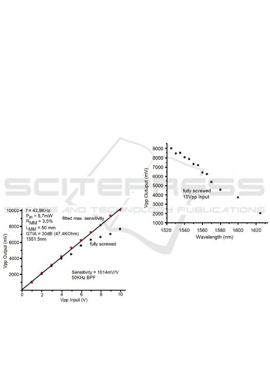
Figure 2 shows two dependences of output
voltage amplitude (mVpp) from the detector device
of Fig. 1a when the excitation voltage amplitude
(Vpp) applied on the PZT disc is varied in the ~ 0 -
10 V range. The vertical axis means the output
voltage signal as captured by the oscilloscope. In the
first dependence, the FC/PC connectors were “fully
screwed” thus concentrically aligning both the SMF
cores. The dependence is clearly sublinear. In the
second dependence, it was kindly unscrewed one of
the sides of the adapter that contains the SMF FC/PC
connectors, keeping the other side totally close. The
FC/PC connector were very slightly misaligned and
carefully fitted to obtain a maximum output
amplitude (“fitted max. sensitivity”) when 10Vpp
voltage excitation is applied. Almost none transmitted
optical power variation was observed in such
procedure by using an optical power meter. However,
it was observed that the amplitude of the signal
PHOTOPTICS 2023 - 11th International Conference on Photonics, Optics and Laser Technology
90
showed at the scope became greater, when compared
with the “fully screwed” connectors. It is likely that
by means of a slightly lateral with/without additional
angular misalignment, higher-order modes than the
fundamental LP
01
are also excited in the fibre core
(Ivanov et al, 2006) (Freitas et al, 2020) (Schulze et
al, 2013). Since the distance along the SMF from the
SM/MM splice to the FC/PC connector is over <1m,
the high-order modes can survive and excites high-
order modes in the s-MMF. By using this strategy, the
sensitivity could be increased. In the reverse sense, it
was reported the near-field contour of the light
propagating along the SMF after the back coupling
from the MMF (Ivanov et al, 2006). Most of the
modulated content is propagating along the cladding
and higher-order modes through the core. A similar
behavior was reported where an amplitude
enhancement of the signal was achieved after lateral
misalignment from 0.9 to 6.8 μm of the fibre’s core
but in the SMF/MMF fusion splice out of the
concentric fitting (Ribeiro and Balod, 2018).
Similarly, the angular misalignment by using the SM-
FC/APC with MM-PC connection can also enhances
the modalmetric sensitivity (Visagathilagar et al,
2014) (Freitas et al, 2020). However, in this paper is
shown that the mode excitation can be carried out
even in the SMF link, i.e., by merely adjusting the
FC/PC-FC/PC connection and monitoring
(optimizing) the output signal amplitude.
Figure 2: Sensitivity dependences of the modalmetric de-
vice using an optical circulator in B2B.
Figure 2 shows a linear dependence when the
FC/PC connector is adjusted as “fitted max.
sensitivity”. A sensitivity of 1014 mVpp/Vpp was
calculated by linear regression. For excitation voltage
amplitudes > 4 Vpp the sensitivity measured for
“fitted max. sensitivity” is higher than for the “fully
screwed” connector. The 1014 mVpp/Vpp sensitivity
was 1014/87 ≈ 11.7 times greater than the 87
mVpp/Vpp measured for the FBG-based opto-
acoustic detector (Leal et al, 2018). By using the
modalmetric detector, very weak acoustic signals as
those generated by applying < 0.05 Vpp amplitude on
the PZT disc was transduced to the optical domain
with good fidelity. The same experiment was carried
out with the FBG-based detector and only excitations
of > 0.5 Vpp amplitude could be properly detected
(Leal et al, 2018). Roughly speaking, the
modalmetric-based optical detector using circulator
presented ~ 10 dB higher sensitivity than the FBG-
based device.
Figure 3 shows the dependence of output voltage
amplitude (mVpp) from the device when the
wavelength of the probing laser is tuned in the 1525-
1625 nm wavelength range and the FC/PC connection
is in the “fully screwed” status. The excitation voltage
amplitude applied on the PZT disc was 10 Vpp and
5.7 mW was again launched to the s-MMF.
Figure 3: Sensitivity dependence of the modalmetric device
using an optical circulator when the wavelength is made to
vary in the 1525-1625 nm range.
The graded-index MMF is ultimately an optical
guide of multi-mode interference (MMI) type. The
spectral response of such structure is periodic fringes
where the periodicity decreases as the fibre length
increases (Kumar et al, 2003). Because of the short
length of the MMF used here, an incomplete
oscillation occurs as shown in Fig. 3 where the
maximum of transmission is close to1525 nm.
Although the scope trace is not shown here, an
improved sensitivity of 1340 mVpp/Vpp was reached
by properly fitting the SMF/SMF connection and
probing the device with 1525 nm wavelength. This
leads a sensitivity of 1340/87 = 15.4 times (~12 dB)
the 87 mVpp/Vpp reached by the FBG-based opto-
acoustic detector (Leal et al, 2018).
Investigations on Sensitivity of Modal Fibre-Interferometer for Acoustic Detection
91

3.2 Optical Circulator + Modalmetric
Setup in Acoustic Transmission
Through a Metallic Billet
Now, a DFB laser emitting around 1550 nm
wavelength and Pin < 5 mW was the optical power
launched to the s-MMF. The TIA gain was set to 40
dB. As is shown in the Fig. 1b, the acoustic waves
propagate along the metallic billet thus resulting in a
weak dynamic strain/stress that occurs due the arrival
of ultrasound in the position where the glued
modalmetric s-MMF is placed. The link was
optimized by simple trial, i.e. by slightly changing the
coupling position of the PZT-transmitters over the top
surface of the billet.
Figure 4 shows the acoustic response, i.e. it shows
the output voltage amplitude (Vpp) from the device
detector when the excitation voltage amplitude (Vpp)
applied on the PZT disc is varied in the ~ 0 – 12.5 V
range. The FC/PC connector was “fully screwed”.
The response is nonlinear thus presenting an
approximate agreement with the B2B transmission
shown by Fig. 2.
Figure 4: Sensitivity dependence of the modalmetric device
using an optical circulator after propagation along 9.5 cm
length of a metallic billet.
The average acoustic sensitivity from 0 to ~ 3 Vpp
voltage amplitude excitation was extracted as to be ~
2000 mV/V. This latter is greater than the 1014 mV/V
obtained in B2B as shown in Fig. 2 because now the
TIA gain is 40 dB instead of 30 dB. Therefore, the
normalized sensitivity regarding the propagation
along the billet is given by 2000/3.17 = 631 mV/V.
Furthermore, as was already reported (Freitas and
Ribeiro, 2021), in B2B measurements using the same
PZT-disc and 25 cm length of s-MMF, an average
acoustic sensitivity of 1074 mV/V was achieved but
constrained to the 0-1 V range of excitation. In the
present paper, a normalized acoustic sensitivity of
631 mV/V with a good linearity at least in the 0 - 3V
amplitude range excitation is measured as seen from
Fig. 4. An increase from 0 - 1V to 0 - 3V of the
dynamic range is here observed due the acoustic
attenuation after propagation along the billet thus
reducing the ultrasound amplitude that strikes the s-
MMF.
Although a similar result was previously
published by our group (Ribeiro and Freitas, 2021),
an important difference should nevertheless be
noticed. In (Ribeiro and Freitas, 2021)and section 3.1,
a tunable laser with 100 kHz linewidth, more
powerful and of higher cost was used as a light
source. In this sub-section, a DFB laser with ~10
MHz linewidth was used as the light source. So far,
we have not carried out studies on the effect of the
laser linewidth on the sensitivity of the modalmetric
devices. However, from the results obtained, it seems
that the performance difference is not significant at
least for external-cavity and DFB lasers.
3.3 2x2 Fibre-Coupler + Modalmetric
Setup in Back-to-Back
Transmission
As is shown in the Fig. 1c, the optical circuit to couple
the light is an 70/30 2x2 fibre-coupler where the
acoustic waves are in back-to-back transmission. The
FC/PC connector in the SMF was “fully screwed”.
The optical probe of the s-MMF launched in the arm
3 was at 1.8 mW power level.
Figure 5 shows the acoustic sensitivity (mVpp)
from the modalmetric detector when the excitation
voltage amplitude (Vpp) applied on the PZT disc is
varied in the ~ 0 – 12.5 V range. The acoustic
sensitivity measurements were performed in three
situations considering the arm 2 terminated by a
FC/PC connector. In the first situation, the ferrule was
immersed in a refractive index matching liquid so that
the reflected signal was virtually null. The curve
marked with blue squares shows a reduced sensitivity
of ~0.66/10 = 66 mVpp/Vpp under 10 Vpp amplitude
excitation. If we take into account that 1.8 mW is
probing the s-MMF, 1.8 x 0.035 = 63 μW power level
is reflected by the cleaved end of s-MMF and < 63
μW will reach the photo-detector. From the
calibration plot of modalmetric response under the
probing power level as can be seen from Fig. 4 of
(Freitas et al, 2020), a sensitivity of << 150 mV/V is
extrapolated and is in good agreement with the 66
mV/V measured even taking into account the 40 dB
TIA amplifying gain. The circuit with 2x2 fibre-
coupler, which presents free port (arm 2) terminated
for null reflection, works only on the basis of the
PHOTOPTICS 2023 - 11th International Conference on Photonics, Optics and Laser Technology
92

modalmetric device as in the case of using the
circulator, but with reduced sensitivity.
Hereafter, the ferrule of arm 2 was cleaned and
dried so that it began to reflect ~3.5% of the light
power. The curve marked with red diamond yields a
sensitivity of 12/12.5 = 960 mVpp/Vpp for 12.5 V
voltage excitation amplitude. There was then a
sensitivity increase of 960/66 = 14.5 times when
compared to the circuit working only as modalmetric.
It should be noted that the behavior of the curve
marked with red diamonds is not linear, which is
consistent with the fact that we have here a “fully-
screwed” FC/PC connector, similar to what was
described in section 3.1. By extending the straight
line between 0 and 4.5 Vpp of the curve marked with
red diamonds, an extrapolated sensitivity of ~20/12.5
= 1600 mVpp/Vpp is obtained for 12.5 Vpp of
voltage excitation amplitude.
Two possible interpretations are outlined here.
The circuit using a 2x2 fibre-coupler with a free port
(arm 2) terminated with ~3.5 % reflection, works as
one of the arms or reference arm of a fibre-optic
Michelson interferometer. The other arm (arm 3) is
the s-MMF, i.e. the reflective modalmetric device.
When arm 2 is terminated with refractive index
matching gel, the light arriving at the PD carries only
the amplitude modulation generated from the splice
when acoustic signals disturb the s-MMF. When the
arm 2 (ferrule) is terminated with a free surface
reflecting 3.5% of the light power, the visibility of the
interferometer increases as the optical powers of arms
2 and 3 reaching the PD are more equalized. Thus, a
possible interpretation for the higher sensitivity
obtained with the Michelson configuration is that
some additional phase modulation generated in the s-
MMF that proceeds through the SMF will be
converted into amplitude modulation when the
optical signals from arm 2 and 3 overlap in the photo-
diode. Therefore, we will have two in-phase
contributions to the output signal: 1
st
) Amplitude
modulated signal due to the conversion of phase
modulation acquired by modal interference (between
modes) in the s-MMF which is converted into
amplitude modulation from the SM/MM fusion
splice. 2
nd
) Amplitude modulated signal generated
from the Michelson interferometer itself that is
formed by the SM fibers of the 2x2 fibre-coupler.
Another possible interpretation is that there may
be an oscillation of light reflected and modulated on
terminal 3 (cleaved end of the s-MMF) and also
reflected on terminals 1 and 4. In this case, when
terminal 2 starts to reflect some power of light, a
higher level of such power starts to oscillate between
arms 3 – (1 and 4), resulting in an increase in the
oscilloscope signal. This possibility is what is called
“light recycling”, described for a Michelson
interferometers in free-space aiming to detect
gravitational waves (Sato et al, 2000).
In a third experiment, the FC/PC ferrule was
placed in physical contact with a mirrored surface so
that most of the light power level was reflected from
arm 2. What was observed is that the signal
disappeared for all launched acoustic signal values up
to at least 12.5 Vpp. The circuit using a 2x2 fibre-
coupler with a free port (arm 2) terminated with a
mirror is causing virtually total reflection that
saturates the TIA when set at 40 dB. However, when
the TIA gain was reduced to 20 dB, an output signal
could be observed with 2 Vpp amplitude for 10 Vpp
excitation. Since the PDA saturates from 20 Vpp
output, an extrapolation of (3.17)
2
x 2 Vpp = 20 Vpp
output could be obtained by using 40 dB TIA gain. It
can be inferred here that there must be an optimal
reflection percentage to maximize the sensitivity of
the device as a whole as illustrated in Fig. 1c.
Figure 5: Sensitivity dependence of the modalmetric device
using an 2x2 fibre-coupler in B2B transmission.
3.4 2x2 Fibre-Coupler + Modalmetric
Setup in Acoustic Transmission
Through a Metallic Billet
As is shown in the Fig. 1d, the optical circuit to couple
the light is an 2x2 fibre-coupler 70/30 where the
acoustic waves propagate along the 9.5 cm length
billet thus in principle resulting in a very weak signal
to be detected. The FC/PC connector in the SMF was
“fully screwed”. The optical probe of the s-MMF
launched in the arm 3 was done at 1.8 mW power
level.
Figure 6 shows the acoustic sensitivity (mVpp)
from the device detector when the excitation voltage
amplitude (Vpp) applied on the PZT disc is varied in
the ~ 0 – 12.5 V range. What can be seen from Fig. 6
is that they are essentially attenuated results when
compared to the sensitivity plot of Fig. 5. For
example, the dry ferrule produced sensitivities of
Investigations on Sensitivity of Modal Fibre-Interferometer for Acoustic Detection
93

12/12.5 = 960 and 5.25/12.5 = 420 mVpp/Vpp for
12.5 Vpp excitation voltage amplitude, respectively.
The physical interpretations are the same as those
given in section 3.3 for the B2B transmission
configuration. We can compare the sensitivity of 420
mVpp/Vpp from Fig.6 referring to the 2x2 coupler,
with 820 mVpp/Vppa from Fig. 4 referring to the
circulator, both showing the sensitivity after
transmission along the billet. The result shown in Fig.
6 refers to a 3.5% reflection from the ferrule of port
2. However, Fig. 6 shows that for 12.5 Vpp excitation
voltage amplitude, an output of ~0.8 Vpp was
achieved with high reflection from the terminal
ferrule in arm 2, but with a TIA gain set to be only 10
dB. Normalizing this last result to that of Fig.5, we
will have an extrapolated sensitivity of (3.17)
3
x 0.8
~ 25.3 Vpp, which gives, 25.3/12.5 ~ 2023
mVpp/Vpp. Although it could be argued that the 0.8
Vpp signal contains some noise contamination, it
should be noted that the 2x2 coupler offers more
degrees of freedom to achieve increased sensitivity
than when using the circulator.
Figure 6: Sensitivity dependence of the modalmetric device
using an 2x2 fibre-coupler in transmission through a 9.5 cm
length billet.
4 CONCLUSIONS
This paper reported a modalmetric device which is of
very simple construction, high sensitivity and can
works as an opto-acoustic detector. The core of a
modalmetric-based device is a short (or long) length
of s-MMF fusion spliced or connectorized with a
SMF. The optical circuit intended to couple, partially
process and recover the light is here described to be a
circulator or a 2x2 fibre-coupler. Below it is outlined
some conclusions from the experimental results as
described in the present paper:
1
a
) By performing a lateral/angular misalignment
in the FC/PC connector between SM fibres, it is
possible to excite LP
01
as well higher-order modes
(Schulze et al, 2013), thus resulting in a more
sensitive interferometric device. Of course,
performing a misaligned fusion splice instead of
connectorization is more practical and mechanically
stable.
2ª) It is possible to increase the sensitivity of the
modalmetric device by making it operate at a
different wavelength, but closer to 1550 nm. In the
present paper was 1525 nm, which is the lower limit
of the tunable laser. The device sensitivities were
measured as 1340 mVpp/Vpp that is ~12 dB greater
than the sensitivities obtained with the FBG-based
detector (Leal et al, 2018).
3ª) It appears that although the coherence
(linewidth) of an external cavity laser or DFB differs
by ~2 orders of magnitude, the sensitivity
performance of the modalmetric is not significantly
changed. An in-depth analysis of this point is left for
a future research.
4
a
) An improved transmission along a 9.5 cm
length metallic billet with circulator and 2x2 coupler
was demonstrated.
5ª) The circuit with 2x2 fibre-coupler presenting a
free port (arm 2) terminated for null reflection, works
only on the basis of the modalmetric device, as in the
previous case of using the circulator.
6ª) The modalmetric circuit using a 2x2 fibre-
coupler but with a free port (arm 2) terminated with
~3.5 % reflectance presented a sensitivity higher than
when is terminated with a null reflectance. In order to
explain such behavior, two suggestions are here
outlined: A superposition of modal and Michelson
fibre interferences; and “light recycling” due
oscillations inside the arms of Michelson
interferometer (Sato et al, 2000). This is an interesting
point to be explored in the future in order to combine
multimodal interference with interference within
single-mode fibre-optic circuits.
7ª) The circuit using a 2x2 fibre-coupler with a
free port (arm 2) terminated with a mirror, causes
virtually total reflection, thus yielding an extrapolated
large sensitivity of 2023 mVpp/Vpp since the TIA
gain is set at 10 dB in transmission through a billet.
It can be inferred here that there may exist an optimal
reflection percentage to maximize the sensitivity.
This is left as a research suggestion for future works.
REFERENCES
Ahmad, T. J., Noui-Mefidi, M. and Arsalan, M. (2014). Per-
formance analysis of downhole acoustic communica-
tion in multiphase flow. In 40thAnnual Conference of
the IEEE Industrial Electronic Society (IECON 2014).
Dallas, TX.
PHOTOPTICS 2023 - 11th International Conference on Photonics, Optics and Laser Technology
94

Chakraborty, S. et al. (2015). Low-power, low-rate ultra-
sonic communications system transmitting axially
along a cylindrical pipe using transverse waves. In
IEEE Transaction Ultrasonic Ferroelectric Frequency
Control, Vol. 62, pp. 1788–1796.
Farr, N., Bowen, A., Ware, J., Pontbriand, C. and Tivey, M.
(2010). An integrated, underwater optical/acoustic
communications system. In IEEE Communications
Magazine.
Freitas, T. A. M. G. and Ribeiro, R. M. (2021). The effects
of scaling and bends in a fiber-optic modalmetric acous-
tic detector. In Microwave and Optical Technology Let-
ters, Vol. 63, 2, pp. 708-713.
Freitas, T. A. M. G., Silva, V. H. and Ribeiro, R. M. (2020).
Sensitivity of fiber-based modalmetric devices intended
for optical detection of acoustic signals. In Microwave
and Optical Technology Letters, 62, 3, pp. 999-1008.
Heifetz, A., Vilim, R. B. and Bakhtiari, S. (2018). Trans-
mission of information by acoustic communication
along metal pathways in nuclear facilities. In Argonne
National Laboratory, Report ANL-18/35.
Ivanov, O. V., Nikitov, S. A. and Gulyavev, Y. V. (2006).
Cladding modes of optical fibers: properties and appli-
cations. In Physics-Uspekhi, 49 (2), pp. 167-191.
Kumar, A., Varshney, R. K., Antony, S. C. and Sharma, P.
(2003). Transmission characteristics of SMS fiber optic
sensor structures. In Optics Communications 219, 215-
221.
Leal, W. A., Carneiro, M. B. R., Freitas, T. A. M. G.,
Marcondes, C. B. and Ribeiro, R. M. (2018). Low-fre-
quency detection of acoustic signals using fiber as an
ultrasonic guide with a distant in-fiber Bragg grating. In
Microwave and Optical Technology Letters, 60, 4, pp.
813-817.
Moccia, M., Consales, M., Iadicicco, A., Pisco, M., Cutolo,
A., Gladi, V. and Cusano, A. (2012). Resonant hydro-
phones based on coated fiber Bragg gratings. In Journal
of Lightwave Technology, 30, 15, 2472-2481.
Oanca, I., Yang, G.Y., Katsifolis, J and Tapanes, E. (1997).
Simultaneous wavelength multiplexed fiber optic com-
munications and cable integrity monitoring technique.
In CLEO, paper WP4, 106.
Ribeiro, R. M. and Balod, Y. C. (2018). Modalmetric inter-
ferometer under Fingerprint disturbances: The effect of
lateral offset between the single-mode and multimode
fiber splice. In Microwave and Optical Technology Let-
ters, 60, 1, pp. 151-157.
Ribeiro, R. M. and Freitas, T. A. M. G. (2021). Modalmetric
Detector in an Acoustic Transmission Along Metallic
Medium. In 2021 SBMO/IEEE MTT-S International
Microwave and Optoelectronics Conference (IMOC),
Fortaleza, Brazil, 24-27 October.
Rudraraju, R. (2010). Ultrasonic data communication
through petroleum. In Master of Science Thesis, Uni-
versity of Akron.
Sato, S. et al. (2000). High-gain power recycling of a Fabry-
Perot Michelson interferometer for a gravitational-
wave antenna. In Applied Optics, 39, 25, pp. 4616-
4620.
Sun, Z., Rocha, B., Wu, K.-T. and Mrad, N. (2013) A Meth-
odological Review of Piezoelectric Based Acoustic
Wave Generation and Detection Techniques for Struc-
tural Health Monitoring. In International J. of Aero-
space Engineering, v. 2013, article ID 928627, 22
pages.
Schulze, C. et al. (2013). Measurement of higher-order
mode propagation losses in effectively single mode fi-
bers. In Optics Letters, 38, 23, pp. 4958-4961.
Trane, G., Mijarez,,R., Guevara, R. and Baltazar, A.
(2015). PZT guided waves sensor permanently attached
on multi-wire AWG12 cables used as communication
medium. In 41st Annual Review of Progress in Quanti-
tative Nondestructive Evaluation, AIP Conference Pro-
ceedings. Boise, ID. (Vol. 1650, no. 1, pp. 631– 639).
Visagathilagar, Y., Katsifolis, J. and Koziol, B. (2014).
Modalmetric fibre sensor. US Patent 8,792,754 B2, July
29, 2014.
Wang, B., Saniie, J., Bakhtiari, S. and Heifetz, A. (2018).
Software defined ultra-sonic system for communication
through solid structures. In 2018 IEEE International
Conference on Electro/Information Technology (EIT),
Rochester, MI.
Wild, G. and Hinckley, S. (2011). A fibre Bragg grating
sensor as a receiver for acoustic communication sig-
nals. In Sensors, 11, 455-471.
Layton, M. R. and Bucaro, J.A. (1979). Optical fiber acous-
tic sensor utilizing mode-mode interference. Applied
Optics, vol 18, No. 5.
Zhou MENG, Wei CHEN, Jianfei WANG, Xiaoyang HU,
Mo CHEN, and Yichi ZHANG (2021). Recent Progress
in Fiber-Optic Hydrophones. In Photonic Sensors,
2021, 11(1): 109–122.
Investigations on Sensitivity of Modal Fibre-Interferometer for Acoustic Detection
95
